Icom AT-140 Instruction Manual
Hf automatic antenna
Hide thumbs
Also See for AT-140:
- Instruction manual (12 pages) ,
- Instruction manual (16 pages) ,
- Service manual (24 pages)
Table of Contents
Advertisement
Quick Links
Advertisement
Table of Contents

Subscribe to Our Youtube Channel
Related Manuals for Icom AT-140


Summary of Contents for Icom AT-140
- Page 1 INSTRUCTION MANUAL HF AUTOMATIC ANTENNA TUNER AT-140...
-
Page 2: Foreword
* The supplied pin connector and connector pins may differ, depending on the version. Icom, Icom Inc. and the Icom logo are registered trademarks of Icom Incorporated (Japan) in Japan, the United States, the Unit- ed Kingdom, Germany, France, Spain, Russia and/or other countries. -
Page 3: Table Of Contents
Re-tuning for a memorized frequency takes approxi- mately 1 second. Super capacitor for memory backup Even if the AT-140 is not used for approximately 1 week, the built-in super capacitor backs up the con- tents of the 45 memories. Low power tune up The AT-140 emits low output power during tuning. -
Page 4: Antenna System
In some countries, HF transceivers can be used Refer to the AH-2b instruction manual for the AH-2b for land mobile operation. Ask your Icom Dealer for and AT-140 installation to your vehicle. Ask your Icom details, since the radio law varies according to each Dealer for details. -
Page 5: Coaxial Cable
ANTENNA SYSTEM n Coaxial cable Insulate the lead-in cable of the AT-140 antenna termi- To prevent erroneous indications, keep cables as far nal and antenna element from other metal objects. away as possible from the flux gate compass. To prevent interference, keep cables as far as possi-... -
Page 6: Installations
Refer to page 4, “PL-259 connector.” • Refer to page 1 “Antenna for ship,” and page 2 “Ground and counterpoise.” e Mount the AT-140 in the desired location. • Refer to page 5, “Mounting.” n Control cable Between the AT-140 and HF marine transceiver, con- Icom offers 10 m (32.8 feet) long control cables. -
Page 7: Pl-259 Connector
• Make sure the base nut is tightened firmly, before tape to secure waterproofing. you tighten the wing nut. (See the Fig.1 to the * The electrical tape is not supplied with the AT-140. right.) • Carefully bend the wire terminal up, after you Fig.2... -
Page 8: Mounting
WARNING! Mount the AT-140 securely with the * The electrical tape is not supplied with the AT-140. supplied nuts and bolts. Otherwise, vibrations and shocks due to waves could loosen the antenna tuner making if fall, causing personal injury. -
Page 9: Control Cable Signals
Antenna current detector output. Time *For the Tuner Through function; Less than 250 milliseconds Key voltage [KEY] During automatic tuning, the AT-140 grounds the key voltage line, and the HF transceiver reduces output power. During automatic tuning Approximately 7.5 V... -
Page 10: Transceiver Setting
In the IC-78, select the antenna tuner type as “AH-4*” in initial set mode. See the IC-78 instruction manual’s * With “AT-130” setting, use of the AT-140 is possible, page 32 for details. however, the Tuner Through function cannot be oper-... -
Page 11: Unit Description And Specifications
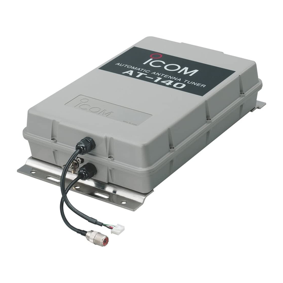
UNIT DESCRIPTION AND SPECIFICATIONS n Unit description 80 mm; 3.1 inches Ground terminal Mounting plate Antenna cable receptacle Control cable receptacle Antenna terminal Mounting plate 91.5 mm; 3.6 inches n Specifications • Frequency coverage : 1.6–30 MHz (with 7 m; 23.0 feet) or longer antenna element) •... - Page 12 Phone: +34 (93) 590 26 70 Fax: +34 (93) 589 04 46 URL: http://www.icomcanada.com URL: http://www.icomspain.com E-mail: info@icomcanada.com E-mail: icom@icomspain.com Icom (Australia) Pty. Ltd. Icom (UK) Ltd. Unit 1/103 Garden Road, Clayton Victoria, 3168, BLACKSOLE HOUSE, ALTIRA PARK, HERNE BAY, Australia KENT, CT6 6GZ, U.K.
Need help?
Do you have a question about the AT-140 and is the answer not in the manual?
Questions and answers