Table of Contents
Advertisement
Quick Links
Download this manual
See also:
Instruction Manual
Advertisement
Table of Contents

Related Manuals for Icom AT-141


Summary of Contents for Icom AT-141
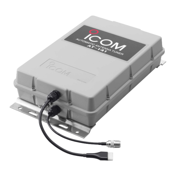
- Page 1 INSTRUCTION MANUAL HF AUTOMATIC ANTENNA TUNER AT-141...
-
Page 2: Foreword
SUPPLIED ACCESSORIES The following accessories are supplied with the AT-141. Icom, Icom Inc. and the logo are registered trademarks of Icom Incorporated (Japan) in the United States, the United King- dom, Germany, France, Spain, Russia and/or other countries. PRECAUTIONS R DANGER HIGH VOLTAGE! NEVER the antenna terminal, ground terminal, antenna or counterpoise while transmitting. -
Page 3: Table Of Contents
Re-tuning for a memorized frequency takes approx. 1 sec. Super capacitor for memory backup Even if the AT-141 is not used for approx. 1 week, the built-in super capacitor backs up contents of the 45 memories. Low power tune up The AT-141 emits low output power during tuning. -
Page 4: Antenna System
ANTENNA SYSTEM I Antenna for ship Required antenna element length Required antenna element length to achieve full per- formance varies according to the lowest frequency: The lowest frequency Required antenna element length 1.6 MHz band 7 m; 23.0 feet or longer 4 MHz band 3 m;... -
Page 5: I Coaxial Cable
I Coaxial cable Insulate the lead-in cable of the AT-141 antenna ter- minal and antenna element from other metal objects. To prevent interference, keep cables as far as possi- ble from an antenna, electric pump and other elec- tronic equipment. -
Page 6: Installations
4 control signal lines as shown below. To prevent RF feedback, use a 4-conductor shielded cable. Con- nect the shield line to the [GND] terminal on the trans- ceiver. Icom offers 10 m (32.8 ft) long optional control cables as at right. D When connecting to Icom IC-M801E... -
Page 7: I Pl-259 Connector
10 mm 10 mm ⁄ inches I Mounting Attach the AT-141 either horizontally or vertically with one of the water drains facing downwards. After mounting, remove the screw in the water drain. Mounting on a Mast/Metal pole Mast/ Using U-bolts... -
Page 8: I Cable Connections
Grounding r Connect the coaxial cable and the control cable to the transceiver as illustrated below. t Ground the transceiver, AT-141 and shield cable of the control cable via the ground terminal. • See p. 2 for grounding details. IMPORTANT!— AT-141 NEVER ground the AT141 via the mounting plate. -
Page 9: Control Cable Signals
AT-141 begins automatic tuning. Start voltage *For tuner through operation; Less than 250 msec. Key voltage [KEY] During automatic tuning, the AT-141 grounds the key voltage line, and the HF transceiver reduces output power. Approx. 7.5 V voltage More than 350 msec.*... -
Page 10: Unit Description And Specifications
UNIT DESCRIPTION AND SPECIFICATIONS I Unit description Ground terminal Water drain screw Antenna cable receptacle Antenna terminal Mounting plate I Specifications • Frequency coverage • Power supply requirement • Current drain • Operating temperature range : –30°C to +60°C • Weight (approx.) •... - Page 11 A-6472H-1EU Printed in Japan © 2005 Icom Inc. Icom America Inc. Icom (Europe) GmbH <Corporate Headquarters> Communication Equipment 2380 116th Avenue N.E., Bellevue, WA 98004, U.S.A. Himmelgeister Str. 100, Phone: +1 (425) 454-8155 Fax: +1 (425) 454-1509 D-40255 Düsseldorf, Germany URL: http//www.icomamerica.com...
Need help?
Do you have a question about the AT-141 and is the answer not in the manual?
Questions and answers