Table of Contents
Advertisement
Quick Links
Advertisement
Table of Contents

Subscribe to Our Youtube Channel
Related Manuals for Icom AT-141


Summary of Contents for Icom AT-141
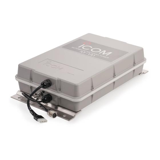
- Page 1 INSTRUCTION MANUAL HF AUTOMATIC ANTENNA TUNER AT-141...
-
Page 2: Table Of Contents
!1 4-pin connector �������������� 1 !2 Connector pins��������������� 4 !3 Ground cable (OPC-412) ���������� 1 Icom, Icom Inc. and the Icom logo are registered trademarks of Icom Incorporated (Japan) in Japan, the United States, the United Kingdom, Germany, France, Spain, Russia and/or other countries. -
Page 3: Miscellaneous Items
5 UNIT DESCRIPTION AND SPECIFICATIONS … 9 6 INSTALLATION EXAMPLE …………………… 10 Super capacitor for memory backup Even if the AT-141 is not used for approximately 1 week, the built-in super capacitor backs up the con- tents of the 45 memories. -
Page 4: System Installation
HF system, the operator can close to the base of your antenna as possible. expect top performance. * The AT-141 is housed in a durable, completely weather resistant case. You don’t have to worry a lot about rain, splash, and so on. -
Page 5: Antenna And Tuners
SYSTEM INSTALLATION Antenna and tuners ■ If your Icom HF system is going aboard a sailboat, Insulator you may use an insulated backstay to make up your antenna system. Your best range will be from an in- sulated backstay because of the long length of the... -
Page 6: Antenna System
ANTENNA SYSTEM Antenna for ship ■ Required antenna element length Required antenna element length to achieve full per- Insulator formance varies, according to the lowest frequency. Backstay operates as The lowest frequency Required antenna element length a long-wire antenna. 1.6 MHz band 7 m;... -
Page 7: Coaxial Cable
ANTENNA SYSTEM Coaxial cable ■ Insulate the lead-in cable of the AT-141 antenna ter- To prevent erroneous indications, keep cables as far minal and antenna element from other metal objects. away as possible from the flux gate compass. To prevent interference, keep cables as far as pos-... -
Page 8: Installations
• Refer to “Control cable” as described below. • Refer to page 7, “Cable connections.” w Connect and solder the PL-259 connector to the t Connect the AT-141’s ground terminal to the ship’s coaxial cable. ground or counterpoise. Refer to “PL-259 connector” as described below. -
Page 9: U-Bolts
Put the crimp-on wire terminal, star washer, and to secure waterproofing. wing nut on the base nut, in that order, then, * The electrical tape is not supplied with the AT-141. tighten the wing nut. Fig.2 • Make sure the base nut is tightened firmly, before you tighten the wing nut. -
Page 10: Rubber Vulcanizing Tape
• See pages 1, 2 and 4 for grounding details. tape to secure waterproofing. IMPORTANT: * The electrical tape is not supplied with the AT-141. NEVER ground the AT-141 via the mounting plate. It is not internally connected to ground. -
Page 11: Control Cable Signals
Less than 1 V to start tuning Time *For tuner through operation; Less than 250 milliseconds Key voltage [KEY] During automatic tuning, the AT-141 grounds the key voltage line, and the HF transceiver reduces output power. During automatic tuning [KEY] Approximately 7.5 V... -
Page 12: Unit Description
UNIT DESCRIPTION AND SPECIFICATIONS Unit description ■ 80 mm Ground terminal Mounting plate Antenna connector Control cable connector Antenna terminal Mounting plate 91.5 mm Specifications ■ • Frequency coverage : 1.6–30 MHz (with 7 m or longer antenna element) • Power supply requirement : 13.6 V DC (supplied from the HF transceiver) •... -
Page 13: Installation Example
INSTALLATION EXAMPLE • Descriptions The following are antenna tuner and antenna installa- tion examples for a non-sail boat. Horizontal element They also explain both transmission and reception performance, for your reference. Vertical Antenna element tuner Antenna tuner location versus the strength of radiation from the antenna element The antenna tuner should be installed outside the vessel as high as possible. - Page 14 INSTALLATION EXAMPLE Antenna element style versus the strength of radiation from the antenna element When the antenna tuner is installed on the deck, the following installation may be possible. The antenna element should be as long as possible, especially for the HF low band, such as the 8 MHz marine band. Good —...
- Page 15 INSTALLATION EXAMPLE Thickness of the Antenna element versus the strength of radiation from the element The thickness of the antenna element does not change communication quality much, but it should be as thick as possible for better radiation from the antenna element. Good —...
- Page 16 A-6472H-1EU-r Printed in Japan © 2005–2013 Icom Inc. 1-1-32 Kamiminami, Hirano-ku, Osaka 547-0003, Japan Printed on recycled paper with soy ink.
Need help?
Do you have a question about the AT-141 and is the answer not in the manual?
Questions and answers