Table of Contents
Advertisement
Quick Links
Advertisement
Table of Contents

Related Manuals for Edimax AR-7287WnA


Summary of Contents for Edimax AR-7287WnA
- Page 1 AR-7287WnA User Manual 04-2017 / v1.0...
-
Page 2: Table Of Contents
Contents 1. PRODUCT INTRODUCTION ........................4 1.1. P ..........................4 ACKAGE ONTENTS 1.2. S ........................4 YSTEM EQUIREMENTS 1.3. S .......................... 4 AFETY RECAUTIONS 1.4. LED S & B ..................... 5 TATUS UTTON EFINITIONS 1.5. F ............................7 EATURES 2. HARDWARE INSTALLATION ........................10 3. - Page 3 4.4.3. URL Filter ..........................76 4.4.4. ACL ............................76 4.4.5. DoS ............................80 4.5. M ..........................82 AINTENANCE 4.5.1. Update ..........................82 4.5.2. Password..........................83 4.5.3. Reboot ..........................84 4.5.4. Time ............................. 85 4.5.5. Log ............................85 4.5.6. Diagnostics .......................... 86 5.
-
Page 4: Product Introduction
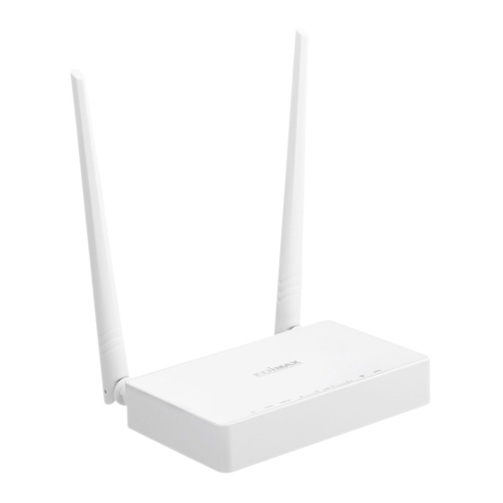
1.1. Package Contents Before you start using this product, please check if there is anything missing in the package and contact your dealer to claim the missing item(s): ADSL2+ router (AR-7287WnA) 12V power adapter 1 meter RJ-45 Ethernet cable ... -
Page 5: Led Status & Button Definitions
User Manual Do not put this device close to heat sources or high temperatures. Keep the device out of direct sunshine. Do not put this device close to a place where it is damp or wet. Do not spill any fluid on this device. - Page 6 User Manual Color Status Description Power Green ADSL2+ router is on. ADSL2+ router is off. ADSL Green ADSL line is synchronized and ready to use. Flashing ADSL line not synchronized. Internet Green Internet connected in router mode Flashing Internet not connected in router mode Device in bridged mode.
-
Page 7: Features
User Manual Rear Panel: Item Description Power On/Off Switches the router on or off. Button Power Power port for included 12V power adapter. Wireless / WPS *Hold for less than 5 seconds to enable wireless signal. Button *Hold for more than 5 seconds to activate WPS function. LAN 1–4 RJ-45 Ethernet ports 1–4. - Page 8 User Manual A single PVC with multiple sessions Multiple PVCs with multiple sessions Auto PVC DHCP server IPv4/IPv6 NAT/NAPT ALG TR-069 SNMP Static route Firmware upgrading through Web, TFTP, or FTP ...
- Page 9 User Manual IP quality of service (QoS) Universal plug and play (UPnP) WLAN with high-speed data transmission rate, compatible with IEEE 802.11b/g/n, 2.4 GHz compliant equipment...
-
Page 10: Hardware Installation
User Manual 2. Hardware Installation Connect the ADSL line. Connect the line port of the router of the device to the modem interface of a splitter using a telephone cable. Connect a telephone to the Phone interface of the splitter using a telephone cable. Connect the Line interface of the splitter to your existing, incoming line. - Page 11 User Manual The following diagrams show how to correctly connect the router, PC, splitter and the telephone sets under two different configurations: Configuration 1 0 shows the correct connection of the router, PC, splitter and the telephone sets, with no telephone set placed before the splitter. Figure 1 –Connection diagram (Without connecting telephone sets before the splitter) Configuration 2...
- Page 12 User Manual Figure 2 - Connection diagram (Connecting a telephone set before the splitter) Note: When Configuration 2 is used, the filter must be installed close to the telephone cable. Do not use the splitter to replace the filter. Installing a telephone directly before the splitter may lead to failure of connection between the device and the central office, or failure of Internet access, or slow connection speed.
- Page 13 User Manual Note: You must use the power adapter included in the package with the router, do NOT attempt to use a third-party power adapter. PC LAN IP configuration. Configure your PC’s LAN settings to automatically obtain an IP address from the router by following the steps below: Click “Start”...
- Page 14 User Manual Locate the “Network Connections” icon and double-click to open network connection settings. Select the “Local Area Connection” icon and right-click it to open the sub- menu, then select “Properties”. Select “Internet Protocol (TCP/IP)” and then click “Properties”...
- Page 15 User Manual Ensure that “Obtain an IP address automatically” and “Obtain DNS server address automatically” are selected and then press “OK”.
-
Page 16: Ip Address Setting
User Manual 3. IP Address Setting To use the router to access the Internet, the PCs in the network must have an Ethernet adapter installed and be connected to the router either directly or through a hub or switch. The TCP/IP protocol of each PC must be installed and the IP Address of each PC has to be set in the same subnet as the router. - Page 17 User Manual 2. Click the Network icon and then select Open Network and Sharing Center to open the Network and Sharing Center window. 3. Click Ethernet to open the Ethernet Status window, and then select Properties. The Local Area Connection window will appear.
- Page 18 User Manual 4. Check your list of Network Components. Select Internet Protocol Version 4 (TCP/IPv4) and click the Properties button. 5. In the Internet Protocol Version 4 (TCP/IPv4) Properties window, select Obtain an IP address automatically and Obtain DNS server address automatically as shown on the following screen.
-
Page 19: Windows 7
User Manual 6. Click OK (shown above) to confirm the setting. Your PC will now obtain an IP address automatically from your router’s DHCP server. Note: Please make sure that the router’s DHCP server is the only DHCP server available on your LAN. 3.2. -
Page 20: Windows Vista
User Manual 4. In the Internet Protocol Version 4 (TCP/IPv4) Properties window, select Obtain an IP address automatically and Obtain DNS server address automatically as shown on the following screen. 5. Click OK to confirm the setting. Your PC will now obtain an IP address automatically from your router’s DHCP server. -
Page 21: Windows Xp
User Manual 3. Check your list of Network Components. You should see Internet Protocol Version 4 (TCP/IPv4) on your list. Select it and click the Properties button. 4. In the Internet Protocol Version 4 (TCP/IPv4) Properties window, select Obtain an IP address automatically and Obtain DNS server address automatically as shown on the following screen. - Page 22 User Manual 3. Check your list of Network Components. You should see Internet Protocol [TCP/IP] on your list. Select it and click the Properties button. 4. In the Internet Protocol (TCP/IP) Properties window, select Obtain an IP address automatically and Obtain DNS server address automatically as shown on the following screen.
-
Page 23: Web Configuration
User Manual 4. Web Configuration This chapter describes how to configure the router by using the Web-based configuration utility. 4.1 Access the Router The following is the detailed description of accessing the router for the first time. Configure the IP address of the PC as 192.168.2.X (2~254), Subnet Mask as 255. 255.255.0. - Page 24 User Manual...
- Page 25 User Manual Click Status > LAN > LAN, the following page appears. You can see lan information,...
- Page 26 User Manual Click Status > LAN > WLAN, the following page appears. You can see Wlan information Click Status > port Mapping , the following page appears. In this page, you can view the statistics of IPTV.
-
Page 27: Wizard
User Manual Click Status > Statistics, the following page appears. In this page, you can view the statistics of each network port. 4.1.2. Wizard In the navigation bar, click Wizard. The tab Wizard only contains Wizard. - Page 28 User Manual 1) Change the VPI or VCI values which are used to define a unique path for your connection. If you have been given specific settings for this to configuration, type in the correct values assigned by your ISP. 2) Please select the Connection Type given by your ISP.
- Page 29 User Manual 3) Here we use PPPoE as an example. Enter the Username, Password and Confirm Password given by your ISP, and then click Next. 4) On the Wireless screen, we use the default SSID, select a Mode. Set a Password or select Disable Security(Disable Security is not recommended.), and then click Next to continue.
- Page 30 User Manual 6) You will see the Complete screen below.
-
Page 31: Setup
User Manual 4.1.3. Setup In the navigation bar, click Setup. The tab Setup contains WAN, LAN and WLAN. 4.1.3.1. WAN Configuration *WAN Choose Setup > WAN > WAN and the page shown in the following figure appears. In this page, you can configure WAN interface of your router. The following table describes the parameters of this page. - Page 32 User Manual Field Description The virtual channel between two points in an ATM network, ranging from 32 to 65535 (1 to 31 are reserved for known protocols) Encapsulation You can choose LLC and VC-Mux. You can choose 1483 Bridged, 1483 MER, PPPoE, PPPoA, 1483 Channel Mode Routed or IPoA.
- Page 33 User Manual Field Description addresses. Enable DHCPv6 Enable or disable dhcpv6 client on this interface, if enable, user can Client specify if the dhcpv6 client request Address or request Prefix. After configuring the parameters of this page, click it to add a new PVC into the Current ATM VC Table.
- Page 34 User Manual The following table describes the parameters and buttons of this page. Field Description Protocol It displays the protocol type used for this WAN connection. ATM VCC The ATM virtual circuit connection assigned for this PPP interface (VPI/VCI). Login Name The user name provided by your ISP.
- Page 35 User Manual Field Description Password The password provided by your ISP. Authenticatio You can choose AUTO, PAP or CHAP. n Method Connection You can choose Continuous, Connect on Demand or Manual. Type Idle Time (s) If choose Connect on Demand, you need to enter the idle timeout time.
- Page 36 User Manual The following table describes the parameters of this page. Field Description The virtual path identifier of the ATM PVC. The virtual channel identifier of the ATM PVC. The QoS category of the PVC. You can choose UBR, CBR, rt-VBR or nrt- VBR.
-
Page 37: Lan
User Manual 4.1.4. 4.1.4.1. LAN Click LAN in the left pane, the page shown in the following figure appears. In this page, you can change IP address of the router. The default IP address is 192.168.1.1, which is the private IP address of the router. - Page 38 User Manual The following table describes the parameters of this page. Field Description Enter the IP address of LAN interface. It is recommended to use an IP Address address from a block that is reserved for private use. This address block is 192.168.1.1- 192.168.255.254.
- Page 39 User Manual Field Description Ethernet It shows the current Ethernet status list. Status Table Address Select the LAN interface on which you want to run MAC Address Control. Control A MAC address to be added. Address Current Allowed It shows the current allowed MAC address list. Address Table 4.1.4.2.
- Page 40 User Manual The following table describes the parameters of this page. Field Description If set to DHCP Server, the router can assign IP addresses, IP default gateway DHCP and DNS Servers to the host in Windows95, Windows NT and other Mode operation systems that support the DHCP client.
- Page 41 User Manual The following table describes the parameters and buttons in this page. Field Description IP Address It displays the IP address assigned to the DHCP client from the router. It displays the MAC address of the DHCP client. Each Ethernet device has a unique MAC address. The MAC address is Address assigned at the factory and it consists of six pairs of hexadecimal character, for example, 00-A0-C5-00-02-12.
- Page 42 User Manual In the DHCP Mode field, choose DHCP Relay. The page shown in the following figure appears. The following table describes the parameters and buttons of this page. Field Description If set to DHCP Relay, the router acts a surrogate DHCP Server and relays DHCP the DHCP requests and reponses between the remote server and the Mode...
- Page 43 User Manual Field Description Changes Undo Click it to refresh this page. 4.1.4.3. DHCP Static Click DHCP Static in the left pane, the page shown in the following figure appears. You can assign the IP addresses on the LAN to the specific individual PCs based on their MAC address.
-
Page 44: Wlan
User Manual 4.1.5. WLAN Choose Setup > WLAN. The WLAN page that is displayed contains Basic, Security, MBSSID, Access Control, Advanced and WPS. 4.1.5.1. Basic Settings Choose WLAN > Basic, and the following page appears. In this page, you can configure the parameters for wireless LAN clients that may connect to the modem. - Page 45 User Manual Field Description must have the same SSID. Enter a descriptive name that is used when the wireless client connecting to the modem. Broadcast Enable or disable this function. SSID Channel You can choose 20MHZ, 40MHZ or 20/40MHZ. Width Control You can choose Upper or Lower.
- Page 46 User Manual The following table describes the parameters of this page. Field Description SSID Type Service Set Identifier, is a name of a local area network Configure the wireless encryption mode. You can choose None, WEP, WPA (TKIP), WPA (AES), WPA2 (AES), WPA2 (TKIP) or WPA2 Mixed. ...
- Page 47 User Manual The following describes the parameters of this page. Field Description Key Length Choose the WEP key length. You can Choose 64-bit or 128-bit. If you choose 64-bit, you can choose ASCII (5 characters) or Hex (10 characters). Key Format ...
- Page 48 User Manual Field Description If you choose 128-bit and ASCII (13 characters), enter any 13 ASCII characters. If you choose 128-bit and Hex (26 characters), enter any 26 hexadecimal characters. Apply Click it to apply the settings temporarily. If you want to save the settings Changes of this page permanently, click Save in the lower left corner.
- Page 49 User Manual It supports 4 virtual access points (VAPs).It is a unique name to identify the modem in the wireless LAN. Wireless stations associating to the modem must have the same name. Enter a descriptive name that is used when the wireless client connecting to the modem. 4.1.5.4.
- Page 50 User Manual Note: The parameters in the Advanced are modified by the professional personnel, it is recommended to keep the default values. The following table describes the parameters of this page. Field Description Select the modem operating in the open system or encryption authentication.
- Page 51 User Manual Field Description Select whether the modem broadcasts SSID or not. You can select Enable or Disable. Broadcast Select Enable, the wireless client searches the modem through SSID broadcasting SSID. Select Disable to hide SSID, the wireless clients can not find the SSID. Relay Wireless isolation.
-
Page 52: Advanced
User Manual There are two ways for the wireless client to establish the connection with the modem through WPS. The modem generates PIN, see the above figure. Click Regenerate PIN to generate a new PIN, and then click Start PBC, In the wireless client tool, enter the PIN which is generated by the modem, start connection. - Page 53 User Manual The following table describes the parameters and buttons of this page. Field Description Enable Select it to use static IP routes. Destinat Enter the IP address of the destination device. Subnet Enter the subnet mask of the destination device. Mask Next Enter the IP address of the next hop in the IP route to the destination device.
- Page 54 User Manual Field Description Route Table Click Show Routes, the page shown in the following figure appears. The table shows a list of destination routes commonly accessed by your network. 4.2.1.2. RIP Click RIP in the left pane, the page shown in the following figure appears. If you are using this device as a RIP-enabled router to communicate with others using Routing Information Protocol (RIP), enable RIP.
-
Page 55: Nat
User Manual Field Description Choose RIP1 indicates the router receives RIP v1 messages. Choose RIP2 indicates the router receives RIP v2 messages. Choose Both indicates the router receives RIP v1 and RIP v2 messages. Send The working mode for sending RIP messages. You can choose RIP1 or Version RIP2. - Page 56 User Manual 4.2.2.2. Virtual Server Click Virtual Server in the left pane, the page shown in the following figure appears. The following table describes the parameters of this page. Field Description Service You can select the common service type, for example, AUTH, DNS,FTP or Type POP3.
- Page 57 User Manual Field Description If you select Usual Service Name, the corresponding parameter has the default settings. If you select User-defined Service Name, you need to enter the corresponding parameters. Choose the transport layer protocol that the service type uses. You can Protocol choose TCP or UDP.
- Page 58 User Manual In the page, you can configure some source IP addresses which use the purge route mode when accessing internet through the specified interface. 4.2.2.5. Port Trigger Click Port Trigger in the left pane, the page shown in the following figure appears.
- Page 59 User Manual Click the Usual Application Name drop-down menu to choose the application you want to setup for port triggering. When you have chosen an application the default Trigger settings will populate the table below. If the application you want to setup isn’t listed, click the User-defined Application Name radio button and type in a name for the trigger in the Custom application field.
-
Page 60: Qos
User Manual Entries in this table allow you to config one IP pool for specified source ip address from lan,so one packet which's source ip is in range of the specified address will select one IP address from pool for NAT. 4.2.3. - Page 61 User Manual Step 1 Enable IP QoS and click Apply to enable IP QoS function. Step 2 Click add rule to add a new IP QoS rule. The page shown in the following figure appears.
-
Page 62: Cwmp
User Manual The following table describes the parameters and buttons of this page. Field Description IP QoS Select to enable or disable IP QoS function. You need to enable IP QoS if you want to configure the parameters of this page. You can choose stream based, 802.1p based or DSCP based. - Page 63 User Manual The following table describes the parameters of this page: Field Description The URL of the auto-configuration server to connect to. User Name The user name for logging in to the ACS. Password The password for logging in to the ACS. Periodic Select Enable to periodically connect to the ACS to check whether the Inform Enable...
-
Page 64: Port Mapping
User Manual Field Description Periodic Specify the amount of time between connections to ACS. Inform Interval Connection Request User Name The connection username provided by TR-069 service. Password The connection password provided by TR-069 service. Debug Show Select Enable to display ACS SOAP messages on the serial console. Message sends Select Enable, the router contacts the ACS to obtain configuration... - Page 65 User Manual Create four rules through Group1 to Group4. The procedure is as follows: Step 1 Select Enable to enable port mapping. Step 2 Select Group1. Then the interfaces are added in the WAN and LAN table. The following page appears. Step 3 Select the interfaces that are respectively added to WAN and LAN.
- Page 66 User Manual The following page appears. Step 5 Click Apply to apply the settings, and the following page appears.
-
Page 67: Others
User Manual In this example, only interfaces of pppoe1 and LAN1 can communicate with each other. That is, only LAN1 can access the Internet through pppoe1 interface. 4.2.6. Others Choose Advanced > Others. The page that is displayed contains Bridge Setting, Client Limit, Tunnel and Others. - Page 68 User Manual 4.2.6.1. Bridge Setting Choose Bridge Setting in the left pane, the page shown in the following figure appears. This page is used to configure the bridge parameters. You can change the settings or view some information on the bridge and its attached ports. The following table describes the parameters and button of this page: Field Description...
- Page 69 User Manual 4.2.6.2. Client Limit Choose Client Limit in the left pane, the page shown in the following figure appears. This page is used to configure the capability of forcing how many devices can access to the Internet. 4.2.6.3. Others Choose Others in the left pane, the page shown in the following figure appears.
-
Page 70: Service
User Manual 4.3. Service In the navigation bar, click Service. The tab Service contains IGMP, UPnP, SNMP, DNS and DDNS. 4.3.1. IGMP Choose Service > IGMP, and the following page appears. The page that is displayed contains IGMP Proxy. 4.3.1.1. IGMP Proxy Click IGMP Proxy in the left pane, the page shown in the following figure appears. -
Page 71: Snmp
User Manual 4.3.3. SNMP Click SNMP in the left pane, the page shown in the following figure appears. You can configure the SNMP parameters. Field Description Enable Select it to enable SNMP function. You need to enable SNMP, and then you SNMP can configure the parameters of this page. -
Page 72: Dns
User Manual Communit The network administrators must use this password to configure the name information of the router. (read- write) 4.3.4. Domain Name System (DNS) is an Internet service that translates the domain name into IP address. Because the domain name is alphabetic, it is easier to remember. The Internet, however, is based on IP addresses. -
Page 73: Ddns
User Manual Field Description the PPPoA, PPPoE or MER enabled PVC(s) during the connection Automati establishment. cally Select it, enter the IP addresses of the primary and secondary DNS server. Manually Apply Click it to save the settings of this page. Changes Reset Click it to start configuring the parameters in this page. -
Page 74: Ftp Server
User Manual Field Description provider Host The DDNS identifier. Name Interface The WAN interface of the router. Enable Enable or disable DDNS function. Usernam The name provided by DDNS provider. Password The password provided by DDNS provider. Email The email provided by DDNS provider. The key provided by DDNS provider. -
Page 75: Ip/Port Filter
User Manual 4.4.2. IP/Port Filter Choose Firewall > IP/Port Filter, the page shown in the following figure appears. The page that is displayed contains IP/Port Filter. 4.4.2.1. IP/Port Filter Click IP/Port Filter in the left pane, the page shown in the following figure appears. Entries in the table are used to restrict certain types of data packets through the gateway. -
Page 76: Url Filter
User Manual 4.4.3. URL Filter Choose Firewall > URL Filter, the page shown in the following figure appears. This page is used to configure the filtered keyword. Here you can add/delete filtered keyword 4.4.4. Choose Firewall > ACL, the page shown in the following figure appears. The page that is displayed contains ACL. - Page 77 User Manual 4.4.4.1. ACL Click ACL in the left pane, the page shown in the following figure appears. In this page, you can permit the data packets from LAN or WAN to access the router. You can configure the IP address for Access Control List (ACL). If ACL is enabled, only the effective IP address in the ACL can access the router.
- Page 78 User Manual The following table describes the parameters and buttons of this page. Field Description Direction Select the router interface. You can select LAN or WAN. In this example, Select LAN is selected. Select it to enable or disable ACL function. Switch Enter the IP address of the specified interface.
- Page 79 User Manual Field Description Allowed SNMP or PING. You can also choose all the services. After setting the parameters, click it to add an entry to the Current ACL Table. Reset Click it to refresh this page. Set direction of the data packets to WAN, the page shown in the following figure appears.
-
Page 80: Dos
User Manual The following table describes the parameters and buttons of this page. Field Description Direction Select the router interface. You can select LAN or WAN. In this example, Select WAN is selected. You can choose Interface or IP Address. Setting Choose the interface that permits data packets from WAN to access the Interface... - Page 81 User Manual...
-
Page 82: Maintenance
User Manual 4.5. Maintenance In the navigation bar, click Maintenance. The Maintenance page that is displayed contains Update, Password, Reboot, Time, Log and Diagnostics. 4.5.1. Update Choose Maintenance > Update. The Update page that is displayed contains Firmware Update and Backup/Restore. Caution: Do not turn off the router or press the Reset button while the procedure is in progress. -
Page 83: Password
User Manual 4.5.1.2. Backup/Restore Click Backup/Restore in the left pane, the page shown in the following figure appears. You can backup the current settings to a file and restore the settings from the file that was saved previously. 4.5.2. Password Choose Maintenance >... -
Page 84: Reboot
User Manual The following table describes the parameters of this page. Field Description Choose the user name for accessing the router. You can choose User Name admin or user. Privilege Choose the privilege for the account. Old Password Enter the old password New Password Enter the password to which you want to change the old password. -
Page 85: Time
User Manual 4.5.4. Time Choose Maintenance > Time, the page shown in the following figure appears. You can configure the system time manually or get the system time from the time server. The following table describes the parameters of this page. Field Description System... -
Page 86: Diagnostics
User Manual 4.5.6. Diagnostics Choose Maintenance > Diagnostics, the page shown in the following page appears. The page that is displayed contains Ping, Tracert, OAM Loopback, ADSL Diagnostic and Diag- test. Select the option that you want to run diagnostics. -
Page 87: Trouble Shooting
5. Trouble Shooting Question Answer Check the connection between the power Why are all the indicators adapter and the power socket. off? Check whether the power switch is turned on. Check the connection between the device and Why is the LAN indicator your PC, hub or switch. - Page 88 WLAN Wi-FI 802.11b/g/n; 2, 4 GHz A simplified DoC shall be provided as follows: Article 10(9) Hereby, Edimax Technology Co., Ltd. declares that the radio equipment type N300 Wireless ADSL2/2+ Modem router is in compliance with Directive 2014/53/EU The full text of the EU declaration of conformity is available at the following internet address: http://www.edimax.com/edimax/global/...
- Page 89 Safety This equipment is designed with the utmost care for the safety of those who install and use it. However, special attention must be paid to the dangers of electric shock and static electricity when working with electrical equipment. All guidelines of this and of the computer manufacture must therefore be allowed at all times to ensure the safe use of the equipment.
- Page 90 EU Declaration of Conformity English: This equipment is in compliance with the essential requirements and other relevant provisions of Directive 2006/95/EC, 2011/65/EC. Français: Cet équipement est conforme aux exigences essentielles et autres dispositions de la directive 2006/95/CE, 2011/65/CE. Čeština: Toto zařízení je v souladu se základními požadavky a ostatními příslušnými ustanoveními směrnic 2006/95/ES, 2011/65/ES.
-
Page 91: Declaration Of Conformity
Declaration of Conformity We, Edimax Technology Co., LTD., declare under our sole responsibility, that the equipment described below complies with the requirements of the European Council directive ( 2014/53/EU Equipment : N300 Wireless ADSL2/2+ Modem router Model No. : AR-7287WnA...
Need help?
Do you have a question about the AR-7287WnA and is the answer not in the manual?
Questions and answers