Edimax AR-7284WnA User Manual
150mbps wireless adsl2/2+ modem router
Hide thumbs
Also See for AR-7284WnA:
- Quick installation manual (12 pages) ,
- Quick installation manual (8 pages)
Table of Contents
Advertisement
Quick Links
Advertisement
Table of Contents

Related Manuals for Edimax AR-7284WnA


Summary of Contents for Edimax AR-7284WnA
- Page 2 English Copyright© by Edimax Technology Co, LTD. all rights reserved. No part of this publication may be reproduced, transmitted, transcribed, stored in a retrieval system, or translated into any language or computer language, in any form or by any means,...
- Page 3 Please contact Edimax at: Edimax Technology co., Ltd, NO. 3, Wu-Chuan 3rd RD Wu-Ku-Industrial Park, Taipei Hsien, Taiwan. R.O.C., +886-2-77396888, +886-2-77396887, sales@edimax.com.tw...
-
Page 4: Table Of Contents
Contents Introduction ..................1 Package List ............... 2 Safety Cautions ..............3 LEDs and Interfaces ............4 System Requirements ............6 Features ................7 Hardware Installation ................8 Connecting the ADSL Router ..........8 USB Installation ..............10 About the Web Configurator ............. 12 Access the Device ............ - Page 5 3.3.5 Filtering Options ............47 3.3.6 QoS Configuration ........... 52 3.3.7 Firewall Settings ............56 3.3.8 DNS ................. 57 3.3.9 Dynamic DNS ............59 3.3.10 Network Tools ............60 3.3.11 Routing ..............72 3.3.12 Schedules ..............76 Management ..............77 3.4.1 System ..............
-
Page 6: Introduction
1 Introduction The AR-7284WnA supports AnnexA mode. It provides four 10/100 base-T Ethernet ports for user. The device provides high-speed ADSL2+ broadband connection to the Internet or Intranet for high-end users, such as net bars and office users. It provides high performance access to the Internet, downstream up to 24 Mbps and upstream up to 1 Mbps. -
Page 7: Package List
1.1 Package List 1 x AR-7284WnA or AR-7284WnB 1 x external splitter 1 x power adapter 2 x telephone cables (RJ-11) 1 x Ethernet cable (RJ-45) 1 x Quick Installation Guide(QIG) 1 x CD (Multi-languages EZmax Wiard / QIG , USB driver... -
Page 8: Safety Cautions
1.2 Safety Cautions Follow the following instructions to prevent the device from risks and damage caused by fire or electric power: Use volume labels to mark the type of power. Only use the power adapter packed within the device package. Pay attention to the power load of the electric outlet or power extension cord. -
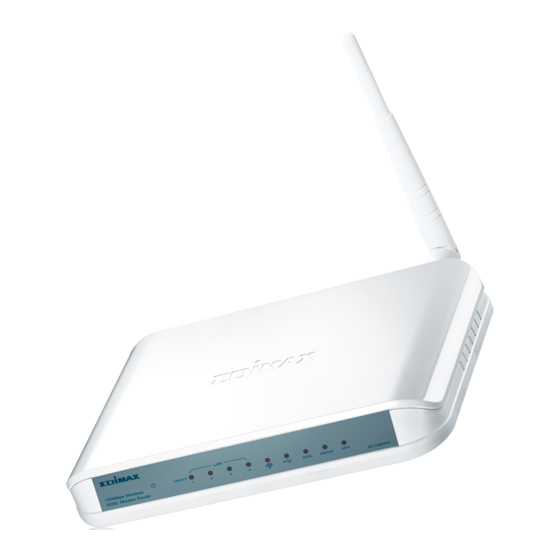
Page 9: Leds And Interfaces
1.3 LEDs and Interfaces Front Panel Figure 1 Front panel The following table describes the LEDs of the device. Color Status Description The power is off. Green The power is on and the initialization is normal. The device is initiating. Blinks The firmware is upgrading. - Page 10 Color Status Description mode, connection present, or the power is off. Connected to network. Network connection failed. The WPS indicator will light for 5 minutes after the WPS service is registered successfully. The WPS indicator will light for 0.2s, and then off for 0.1s when the WPS button is pressed and the network card is ready for register.
-
Page 11: System Requirements
Rear Panel Figure 2 Rear panel The following table describes the interface of the device. Interface/Button Description RJ-11 interface that connects to the telephone set Line through the telephone cable. Press the button for 3 seconds to enable WPS. WPS/Reset Press the button for 8 seconds to restore factory default configurations and reboot the device. -
Page 12: Features
Internet Explorer V5.0 or higher, Netscape V4.0 or higher, or Firefox 1.5 or higher 1.5 Features The device supports the following features: Various line modes External PPPoE dial-up access Internal PPPoE and PPPoA dial-up access Leased line mode Zero installation PPP bridge mode (ZIPB) 1483B, 1483R, and MER access Multiple PVCs (up to eight), PVCs are independent Single PVC with multiple sessions... -
Page 13: Hardware Installation
2 Hardware Installation 2.1 Connecting the ADSL Router Step 1 Connect the ‘Line’ port of the device and the ‘Modem’ port of the ADSL splitter with a telephone cable. Connect the phone to the ‘Phone’ port of the splitter through a telephone cable. Connect the incoming line to the ‘Line’... - Page 14 Figure 3 Connection diagram (without telephone sets before the splitter) Connection type 2: Figure 4 displays the application diagram for the connection of the device, PC, splitter and telephone sets when a telephone set is placed before the splitter. As illustrated in the following figure, the splitter is installed close to the device.
-
Page 15: Usb Installation
Installing a telephone before the splitter may cause connection problem between the device and the central office, or failure of Internet access, or slow connection speed. If you really need to add a telephone set before the splitter, you must add a microfilter before a telephone set. Do not connect several telephones before the splitter or connect several telephones with one microfilter. - Page 16 Step 5 The dialog will instruct you to choose driver from specific location.
-
Page 17: About The Web Configurator
3 About the Web Configurator This chapter describes how to configure the device by the Web-based configuration utility. 3.1 Access the Device Follow the following instructions to access the device for the first time. Step 1 Open the Internet Explorer (IE) browser and enter http://192.168.2.1. -
Page 18: Setup
If you successfully logged in as the super user, the web page as shown in the following figure appears. 3.2 Setup 3.2.1 Wizard Wizard enables fast and accurate configuration of Internet connection and other important parameters. The following sections describe these configuration parameters. When subscribing to a broadband service, you should be aware of the connection method. - Page 19 Step 1 Choose Setup > Wizard. The page shown in the following figure appears. Step 2 Click Setup Wizard. The page shown in the following figure appears. Step 3 There are four steps to configure the device. Click Next to continue.
- Page 20 Step 4 Set the time and date.
- Page 21 Step 5 Configure the Internet connection. Select the country and ISP. Set the VPI and VCI. If you failed to find the country and ISP from the drop-down lists, select Others. Click Next. If the Protocol you selected is PPPoE or PPPoA, the page shown in either of the two following figures appears.
- Page 22 Set the user name and password here,which is provided by your ISP. If the Protocol is Dynamic IP, the page shown in the following figure appears. Click Next, the page shown in the following figure appears.
- Page 23 Configure the wireless network. Enter the information and click Next.
- Page 24 If the Protocol is Bridge, the page shown in the following figure appears.
- Page 25 If the Protocol is Static IP, the page shown in the following figure appears.
- Page 26 Enter the IP Address, Subnet Mask, Default Gateway, and Primary DNS Server. Click Next. The page shown in the following page appears. Figure 5...
- Page 27 Step 6 Configure the wireless network. Enter the information and click Next. Step 7 When the settings are complete, click Apply to apply the settings. Note: In each step of the Wizard page, you can click Back to review or modify settings in previous page. Click Cancel to exit the wizard page.
-
Page 28: Internet Setup
3.2.2 Internet Setup Choose Setup > Internet Setup. The page shown in the following figure appears. In this page, you can configure the WAN interface of the device. Click Add. The page shown in the following figure appears. - Page 29 Click Apply. The page shown in the following figure appears.
-
Page 30: Wireless Setup
3.2.3 Wireless Setup This section describes the wireless LAN and some basic configuration. Wireless LANs can be as simple as two computers with wireless LAN cards communicating in a pear-to-pear network or as complex as a number of computers with wireless LAN cards communicating through access point which bridges network traffic to wired LAN. - Page 31 3.2.3.1 Wireless Basics In the Wireless Setup page, click Wireless Basics. The page shown in the following figure appears. In this page, you can configure the parameters that wireless LAN clients can used to connect to this device. Click Apply to save the settings.
- Page 32 3.2.3.2 Wireless Security In the Wireless Setup page, click Wireless Security. The page shown in the following figure appears. Wireless security is vital to your network to protect the wireless communication among wireless stations, access points and wired network. Click Apply to save the settings.
-
Page 33: Local Network
3.2.4 Local Network You can configure the LAN IP address according to actual requirements. The preset IP address is 192.168.1.1. You can use the default settings and DHCP service to manage the IP settings for the private network. The IP address of the device is the base address used for DHCP. - Page 34 the pool used for DHCP. The IP address pool can contain up to 253 IP addresses. Click Apply to save the settings. In the Local Network page, you can assign IP addresses on the LAN to specific individual computers based on their MAC addresses.
-
Page 35: Time And Date
The NUMBER OF DYNAMIC DHCP CLIENTS page shows the current DHCP clients (PC or Laptop) connected to the device and the detailed information of the connected computer(s). 3.2.5 Time and Date Choose Setup > Time and Date. The page shown in the following figure appears. -
Page 36: Logout
Select the specific time server and the time zone from the corresponding item in drop-down lists. Select Enable Daylight Saving if necessary. Click Apply to save the settings. 3.2.6 Logout Choose Setup > Logout. The page shown in the following figure appears. - Page 37 your wireless performance. The default settings provide the best wireless radio performance in most of environments.
- Page 38 3.3.1.1 Advanced Settings Select Advance Settings. The page shown in the following figure appears. These settings are only for technically advanced users who have sufficient knowledge about wireless LAN. Do not change these settings unless you know the effect of changes on the device.
- Page 39 Click Apply to save the settings. 3.3.1.2 MAC Filtering Select MAC Filtering. The page shown in the following figure appears.
- Page 40 Click Add. The page shown in the following figure appears. Click Apply to save the settings.
- Page 41 3.3.1.3 Security Settings Select Security Settings. The page shown in the following figure appears. Select the SSID that you want to configure from the drop-down list. Select the encryption type from the Security Mode drop-down list.You can select None, WEP, AUTO (WPA or WPA2), WPA Only, or WPA2 Only.
- Page 42 If you select AUTO (WPA or WPA2), WPA Only, or WPA2 Only, the page shown in the following figure appears.
- Page 43 Click Apply to save the settings.
- Page 44 3.3.1.4 WPS Settings Select WPS Settings. The page shown in the following figure appears. WPS Authentication: The WPS service is enabled by default. There are three setting methods you can use in the Wi-Fi Protected Setup. In order to use wps authentication, you can select one method from three methods.
-
Page 45: Port Forwarding
3.3.2 Port Forwarding This function is used to open ports on your device and redirect data from those ports to a single PC on your network (WAN-to-LAN traffic). It allows remote users to access services on your LAN, such as FTP for file transfers or SMTP and POP3 for e-mail. - Page 46 Select a service for a preset application, or enter a name in the Custom Server field. Enter an IP address in the Server IP Address field, to appoint the corresponding PC to receive forwarded packets. The Ports show the ports that you want to open on the device. The TCP/UDP means the protocol type of the opened ports.
-
Page 47: Dmz
3.3.3 Since some applications are not compatible with NAT, the device supports the use of a DMZ IP address for a single host on the LAN. This IP address is not protected by NAT and it is visible to agents on the Internet with the correct type of software. - Page 48 This page provides two useful tools for restricting the Internet access. Block Websites allows you to quickly create a list of all websites that you wish to stop users from accessing. Block MAC Address allows you to control when clients or PCs connected to the device are allowed to access the Internet.
- Page 49 3.3.4.1 Block Website In the Parental Control page, click Block Website. The page shown in the following figure appears. Click Add. The page shown in the following page appears. Enter the website in the URL field. Select the Schedule from drop-down list, or select Manual Schedule and select the corresponding time and days.
- Page 50 Click Submit to add the website to the BLOCK WEBSITE Table. The page shown in the following figure appears. 3.3.4.2 Block MAC Address In the Parental Control page, click Block MAC Address. The page shown in the following figure appears. Click Add.
- Page 51 Enter the user name and MAC address and select the corresponding time and days. Click Submit to add the MAC address to the BLOCK MAC ADDRESS Table.
-
Page 52: Filtering Options
3.3.5 Filtering Options Choose ADVANCED > Filtering Options. The Filtering Options page shown in the following figure appears. 3.3.5.1 Inbound IP Filtering By default, all incoming IP traffic that does not originate from the internal network is blocked when the firewall is enabled. Normal outbound requests created by web browsing, email and other software you run, work as usual as the requests originated from your internal network. - Page 53 Click Add to add an inbound IP filter. The page shown in the following figure appears.
- Page 54 Enter the Filter Name and specify at least one of the following criteria: protocol, source/destination IP address, subnet mask, and source/destination port. Click Apply to save the settings. Note: The settings only apply when the firewall is enabled. The ACTIVE INBOUND FILTER shows detailed information about every created inbound IP filter.
- Page 55 In the Filtering Options page, click Outbound IP Filtering. The page shown in the following figure appears. Click Add to add an outbound IP filter. The page shown in the following figure appears.
- Page 56 Enter the Filter Name and specify at least one of the following criteria: protocol, source/destination IP address, subnet mask, and source/destination port. Click Apply to save the settings. 3.3.5.3 Bridge Filtering In the Filtering Options page, click Bridge Filtering. The page shown in the following figure appears.This page is used to configure bridge parameters.
-
Page 57: Qos Configuration
Click Apply to save the settings. 3.3.6 QoS Configuration Choose ADVANCED > QOS Config. The QoS Configuration page shown in the following figure appears. - Page 58 3.3.6.1 QoS Interface In the QoS Configuration page, click QoS Interface Config. The page shown in the following figure appears. In this page, you can configure bandwidth control. Click Edit, the page shown in the following figure appears. After configuration, click Apply to make configurations take effect.
- Page 59 3.3.6.2 QoS Queue Configuration In the QoS Configuration page, click QoS Queue Config. The page shown in the following figure appears. In this page, you can configure the priority of queue. Click Add, the page shown in the following figure appears. After configuration, click Apply to take the configurations effect.
- Page 60 Click Add, the page shown in the following figure appears.
-
Page 61: Firewall Settings
After configuration is done, click Apply to make the configuration take effect. 3.3.7 Firewall Settings A denial-of-service (DoS) attack is characterized by an explicit attempt by attackers to prevent legitimate users from using that service. Examples include the following The attackers attempt to flood a network, thereby preventing legitimate network traffic The attackers attempt to disrupt connections between two machines, thereby preventing access to a service... -
Page 62: Dns
from accessing a service The attackers attempt to disrupt service to a specific system or person. Port scan protection is designed to block attempts to discover vulnerable ports or services that might be exploited in an attack from the WAN. Choose ADVANCED >... - Page 63 the name into the corresponding IP address. For example, the domain name www.example.com might be translated to 198.105.232.4. The DNS system is, in fact, its own network. If one DNS server does not know how to translate a particular domain name, it asks another one, and so on, until the correct IP address is returned.
-
Page 64: Dynamic Dns
3.3.9 Dynamic DNS The device supports dynamic domain name service (DDNS). The dynamic DNS service allows a dynamic public IP address to be associated with a static host name in any of the many domains, and allows access to a specified host from various locations on the Internet. -
Page 65: Network Tools
DDNS provider: Select one of the DDNS service provider from the down-list. Available service providers include DynDns.org and dlinkddns.com. Host Name: Enter the host name that you registered with your DDNS service provider. Username: Enter the user name for your DDNS account. Password: Enter the password for your DDNS account. - Page 67 3.3.10.1 Port Mapping Choose ADVANCED > Network Tools and click Port Mapping. The page shown in the following figure appears. In this page, you can bind the WAN interface and the LAN interface to the same group. Click Add to add a new port mapping. The page shown in the following figure appears.
- Page 68 The procedure for creating a mapping group is listed as follows: Step 1 Enter the group name. Step 2 Select interfaces from the Available Interface list and click the <- arrow button to add them to the grouped interface list, in order to create the required mapping of the ports.
- Page 69 3.3.10.2 IGMP Proxy Choose ADVANCED > Network Tools and click IGMP Proxy. The page shown in the following figure appears. IGMP proxy enables the system to issue IGMP host messages on behalf of hosts that the system discovered through standard IGMP interfaces. The system acts as a proxy for its hosts after you enable it.
- Page 70 After configuration, click Apply to save the settings. 3.3.10.4 UPnP Choose ADVANCED > Network Tools and click UPnP. The page shown in the following figure appears.
- Page 71 In this page, you can configure universal plug and play (UPnP). The system acts as a daemon after you enable UPnP. UPnP is used for popular audio / video software. It allows automatic discovery of your device in the network. If you are concerned about UPnP security, you can disable it.
- Page 72 The AR-7284WnA supports AnnexA mode, so the AnnexB is not enabled. Click Apply to save the settings.
- Page 73 3.3.10.6 SNMP Choose ADVANCED > Network Tools and click SNMP. The page shown in the following figure appears. In this page, you can set SNMP parameters. Read Community: The network administrator must use this password to read the information of this device. Set Community: The network administrator must use this password to configure the information of this device.
- Page 74 3.3.10.7 TR069 Choose ADVANCED > Network Tools and click TR-069. The page shown in the following figure appears. In this page, you can configure the TR069 CPE. Click Apply to save settings.
- Page 75 3.3.10.8 Certificates Choose ADVANCED > Network Tools and click Certificates. The Certificates page shown in the following figure appears. In the Certificates page, click Trusted CA. The page shown in the following figure appears. Click Input Certificate, the page shown in the following figure appears.
- Page 76 Click Apply to save the settings.
-
Page 77: Routing
3.3.11 Routing Choose ADVANCED > Routing. The page shown in the following page appears. 3.3.11.1 Static Route Choose ADVANCED > Routing and click Static Route. The page shown in the following figure appears. This page is used to configure the routing information. In this page, you can add or delete IP routes. - Page 78 Click Add to add a static route. The page shown in the following figure appears. Destination Network Address: The destination network address. Subnet Mask: The subnet mask of the destination network. Use Gateway IP Address: The gateway IP address of the destination network.
- Page 79 Click Apply to save the settings. 3.3.11.2 Default Gateway Choose ADVANCED > Routing and click Default Gateway. The page shown in the following figure appears. Click Apply to save the settings.
- Page 80 3.3.11.3 RIP Settings Choose ADVANCED > Routing and click RIP Settings. The page shown in the following figure appears. This page is used to select the interfaces on your device that use RIP and the version of the protocol being used. If you are using this device as a RIP-enabled device to communicate with others using the routing information protocol, enable RIP and click Apply to save the settings.
-
Page 81: Schedules
3.3.12 Schedules Choose ADVANCED > Schedules. The page shown in the following figure appears. Click Add to add schedule rule. The page shown in the following figure appears. Click Submit to save settings. -
Page 82: Management
3.4 Management 3.4.1 System Choose Management > System Management. The System page shown in the following figure appears. In this page, you can reboot device, back up the current settings to a file, restore the settings from the file saved previously, and restore the factory default settings. -
Page 83: Firmware Update
Backup Setting: Save the settings to the local hard drive. Select a location on your computer to back up the file. You can name the configuration file. Update Setting: Click Browse to select the configuration file of device and click Update Settings to begin restoring the device configuration.. -
Page 84: Access Controls
Step 2 Click Update Firmware to copy the file. The device loads the file and reboots automatically. Notice: Do not turn off your device or press the reset button while this procedure is in progress. 3.4.3 Access Controls Choose Management > Access Controls. The Access Controls page shown in the following figure appears. - Page 85 3.4.3.1 Account Password In the Access Controls page, click Account Password. The page shown in the following figure appears. In this page, you can change the password of the user and set time for automatic logout. You should change the default password to secure your network.
- Page 86 Click Apply to save the settings. 3.4.3.2 Services In the Access Controls page, click Services. The page shown in the following figure appears. In this page, you can enable or disable the services that are opened to remote host. For example, if telnet service is enabled, the remote host can access the device by telnet through port 23.
- Page 87 3.4.3.3 IP Address In the Access Controls page, click IP Address. The page shown in the following figure appears. In this page, you can configure the IP address used with access control list (ACL). If ACL is enabled, only devices with the specified IP addresses can access the device.
-
Page 88: Diagnostics
3.4.4 Diagnostics Choose Management > Diagnostic. The page shown in the following figure appears. In this page, you can test the device. Click Run Diagnostics Test to run diagnostics. 3.4.5 Log Configuration Choose Management > Log Configuration. The System Log page shown in the following figure appears. -
Page 89: Status
This page displays event log data in the chronological manner. You can read the event log from the local host or send it to a syslog server. Available event severity levels are as follows: Emergency, Alert, Critical, Error, Warning, Notice, Informational and Debugging. - Page 90 The page displays the summary of the device status. It includes the information of firmware version, upstream rate, downstream rate, uptime and Internet configuration (both wireless and Ethernet statuses).
-
Page 91: Wireless Clients
3.5.2 Wireless Clients Choose Status > Wireless Clients. The page shown in the following page appears. The page displays authenticated wireless stations and their statuses. 3.5.3 DHCP Clients Choose Status > DHCP Clients. The page shown in the following page appears. This page displays all client devices that obtain IP address from the device. -
Page 92: Logs
3.5.4 Logs Choose Status > Logs. The page shown in the following figure appears. Click Refresh to refresh the system log shown in the table. -
Page 93: Statistics
3.5.5 Statistics Choose Status > Statistics. The page shown in the following figure appears. This page displays the statistics of the network and data transfer. This information helps technicians to identify if the device is functioning properly. The information does not affect the functionality of the device. -
Page 94: Route Info
3.5.6 Route Info Choose Status > Route Info. The page shown in the following figure appears. The table shows a list of destination routes commonly accessed by the network. - Page 95 This equipment has been tested and found to comply with the limits for a Class B digital device, pursuant to Part 15 of FCC Rules. These limits are designed to provide reasonable protection against harmful interference in a residential installation. This equipment generates, uses, and can radiate radio frequency energy and, if not installed and used in accordance with the instructions, may cause harmful interference to radio communications.
- Page 96 Federal Communications Commission (FCC) Radiation Exposure Statement This equipment must be installed and operated in accordance with provided instructions and a minimum 20 cm spacing must be provided between computer mounted antenna and person’s body (excluding extremities of hands, wrist and feet) during wireless modes of operation. The equipment version marketed in US is restricted to usage of the channels 1-11 only.
- Page 97 EFTA member states: Iceland, Liechtenstein, Norway, and Switzerland. EU Countries not intended for use None A declaration of conformity is available on www.edimax.com N20379...
Need help?
Do you have a question about the AR-7284WnA and is the answer not in the manual?
Questions and answers