Table of Contents
Advertisement
Quick Links
Advertisement
Table of Contents

Related Manuals for Vivax vLoc-9800

Summary of Contents for Vivax vLoc-9800
- Page 1 User Handbook (English Edition) Version 1.0...
-
Page 2: Table Of Contents
Distributors and Service Centers Closest to You: ..............5 vLoc-9800 Receiver ..........................6 vLoc-9800 Receiver ......................... 6 Charging the Receiver Batteries ....................7 vLoc-9800 Receiver Display ....................8 Locating Mode (Response) ..................... 8 3.4.1 Auto Left/Right Mode ......................8 3.4.2 Manual Left/Right Mode (Available on some models) ............ - Page 3 Saving a Configuration ......................19 Configuration Lock Dongle ....................20 Icon Summary ........................21 Loc-10Tx Transmitter ..........................22 Loc-10Tx Transmitter Overview ..................... 22 5.1.1 Transmitter Battery ......................23 5.1.2 Removing the Battery Tray ....................23 5.1.3 Replacing the Alkaline Battery ..................23 5.1.4 Rechargeable Batteries .....................
- Page 4 Rechargeable Batteries ......................38 Loc-1Tx Transmitter Operation ....................38 Using the vLoc-9800 ..........................39 Using the Receiver ........................ 39 8.1.1 Line Locating ........................39 8.1.2 Depth & Current Measurement ..................39 8.1.3 Sonde Location ......................... 40 Passive or Active Location ....................40 8.2.1...
- Page 5 9.18 Loc-5Tx Battery Pack (NiMH) ....................54 9.19 Loc-5Tx Alkaline Battery Tray .................... 54 9.20 Loc-5Tx/10Tx Charger ......................54 9.21 Loc-10Tx Rechargeable Battery Tray ................54 9.22 Loc-10Tx Alkaline Battery Tray ..................54 Glossary ..............................55 Page 4...
-
Page 6: General Safety & Care Information
Do NOT assume that if the plug fits it is the correct charger – a charger with the correct part number • MUST be used – just because it is a Vivax-Metrotech charger and the plug fits does NOT mean it is the correct charger. -
Page 7: Lithium-Ion Batteries (Rechargeable)
Always dispose of batteries responsibly. 1.4.6 Transportation of Lithium-ion and Lithium Metal Batteries The Lithium-ion and Lithium metal batteries used in Vivax-Metrotech products meet the required safety • standards and include the designated protection circuitry. -
Page 8: 1.6 Care When Interpreting The Information Provided By The Locator
Operation is subject to the following two conditions: (1) this device may not cause interference, and (2) • this device must accept any interference that may cause undesired operation of the device. EUROPE Vivax-Metrotech confirms that the location system is compliant with relevant provision of European • directive 1999/5/EC. ETSI EN 300 330-2 : 2006. -
Page 9: Service & Support
Service & Support Service & Support Serial Number and Software Revision Number Always quote your receiver and transmitter model number, serial number and software revision number when requesting product support. They can be found as follows: (for reference only) Model & Serial Number NOTE The transmitter Model &... -
Page 10: Distributors And Service Centers Closest To You
United State of America Europe Vivax-Metrotech Corporation SebaKMT 3251 Olcott Street, Seba Dynatronic Santa Clara, CA 95054, USA Mess-und Ortungstechnik GmbH Website : www.vivax-metrotech.com Dr.-Herbert-Iann-Str. 6, 96148 Baunach, Germany Sales & Sales Support: T/Free : +1-800-446-3392 : +49-9544-680 : +1-408-734-1400... -
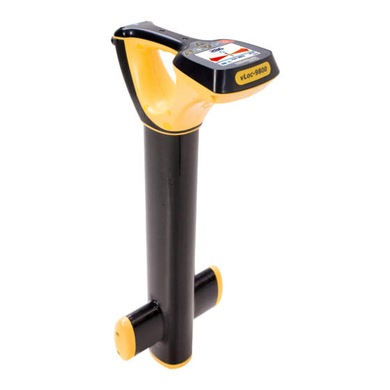
Page 11: Vloc-9800 Receiver
Receiver vLoc-9800 Receiver vLoc-9800 Receiver The vLoc-9800 is a Precision Location System designed to meet the needs of Utility Companies and their contractors. The following describes the features and use of the receiver: Bluetooth Module (Not available for vLoc-... -
Page 12: Charging The Receiver Batteries
Receiver Charging the Receiver Batteries The vLoc-9800 can be used with either alkaline batteries or it can be supplied with an interchangeable rechargeable battery pack. Icon A Icon B When alkaline battery is used, Icon A will appear on the screen. When the rechargeable battery pack is used, Icon B will be displayed. -
Page 13: Vloc-9800 Receiver Display
Moving Pointer On/Off Switch Locating Mode (Response) The vLoc-9800 receiver has an array of antennas; these can be toggled through different configurations (modes) to provide different responses to the signals radiating from the buried pipes and cables. The modes are: 3.4.1... -
Page 14: Manual Left/Right Mode (Available On Some Models)
Receiver As the locator is moved from left to right across the cable the moving bar will move accordingly. When the moving bar is directly over the circle (indicating the cross section of a cable or pipe), the locator is directly over the target line. -
Page 15: Sonde Mode
Sonde and it gives the conventional peak response. The vLoc-9800 receiver must be used in a different orientation when locating a Sonde – due to the way the signal from the Sonde radiates. With the front of the receiver pointing across suspected direction of the Sonde –... -
Page 16: Setup Menu
Frequency Selection Pushbutton The vLoc-9800 receiver is capable of locating a number of frequencies. A list of these frequencies can be accessed using the setup menu. The setup menu allows the operator to select the frequencies they wish to use regularly. The frequency select pushbutton on the main receiver pad is used to toggle through the frequencies defined in the setup menu. - Page 17 Receiver IMPORTANT When locating a cable or pipe (“Line”) – the instrument should be in “Peak” or “Left/Right” mode and the depth and current measurements should only be taken with the bottom of the receiver standing on the ground and directly in line with the target line.
-
Page 18: Mylocator2
MyLocator2 configuration tool is a software package that enables the operator to configure vLoc series 2 locators. The software is compatible with Window XP, Vista and 7. To install, use the link on the Vivax- metrotech web site and follow the installation instructions. A MyLocator2 shortcut icon will appear on your desktop. - Page 19 MyLocator2 Connect the vLoc-9800 Receiver to the PC using a USB to Mini USB cable. The PC should recognize the vLoc-9800 and the display will now change to the below or similar. If connected to the web, MyLocator2 will check at this stage to see if there is a newer version of MyLocator2 or locator software is available.
-
Page 20: Splash Screen
MyLocator2 Splash Screen 1. Click the Spash Screen tab. Click on the “Open” button. Browse your computer to find the picture that is intended to be the splash screen. 2. The software will accept the following formats: JPEG, BMP, GIF, PNG, ICO. 3. -
Page 21: Software Update
MyLocator2 Software Update 1. With the locator switched on and connected to the computer, click on the “Software Update” tab. 2. A screen similar to the one below should be shown. 3. If connected to the Web, MyLocator2 will indicate if a newer version of software is available. If you wish to download it select “Yes”... -
Page 22: Advanced Configuration Tool
• Switch off frequency selections By doing this, the locator is simplified and tailored exactly to the customer requirements. The configuration can be saved as a “config” file and used to configure other vLoc-9800 locators. This ensures consistency throughout the locator fleet. -
Page 23: Switch On/Off User Menu Settings
MyLocator2 Switch On/Off User Menu Settings 1. With the locator switched on and connected to the host computer click on the “Menu Settings” tab. 2. A screen similar to the one below should be shown. If not, click on the “Get Cfg” icon on the top bar. This will load the configuration of the connected locator to the host pc. -
Page 24: Switching On/Off Frequency Selections
MyLocator2 Switching On/Off Frequency Selections 1. Click on the “Frequencies” tab. A screen similar to the one below should be shown. 2. Each row is color coded: Grey indicates that frequency is not selected for either the menu or the frequency key. •... -
Page 25: Configuration Lock Dongle
MyLocator2 Configuration Lock Dongle A Configuration Lock dongle is available that allows “lockout” of features and functions so that operators are forced to use particular settings. The dongle is also used to unlock these features. To activate the dongle, plug it into any USB socket on the host computer. With the dongle active, the MyLocator2 screen will look similar to the picture below. -
Page 26: Icon Summary
MyLocator2 7. Now click on the “Send Cfg” icon to send it to the locator. 8. To activate the new configuration switch the locator off and on. Icon Summary Icon Function Opens a previously saved configuration. Saves a configuration created by the operator to a file of your choice. Either “Send”... -
Page 27: Loc-10Tx Transmitter
Loc-10Tx Transmitter Loc-10Tx Transmitter Loc-10Tx Transmitter Overview The Loc-10Tx transmitter is a rugged portable transmitter powered by alkaline “D” cells or Ni-MH (Nickel Metal Hydride) rechargeable batteries. The following describes the features and uses of the transmitter. Display Frequency Being Transmitted (200 kHz Output Setting (Step) (filled box indicates available in some country) current level has been reached, empty box... -
Page 28: Transmitter Battery
WARNING Alkaline Batteries – insert alkaline batteries (x12) as shown: 5.1.4 Rechargeable Batteries Do NOT attempt to replace the rechargeable batteries or remove battery covers – return to Vivax- • Metrotech or a Vivax-Metrotech approved service centers for replacement. WARNING Use only Vivax-Metrotech recommended charger. -
Page 29: Re-Fitting The Battery Tray
Two pins are used for power from external 12V DC source. A 12V DC power cable is supplied and is designed to be connected to an automobile cigarette lighter socket. Contact Vivax-Metrotech or a Vivax-Metrotech approved service center for wiring diagram of plug, if attempting to repair any of the “charging” leads. 5.1.6 Battery Charging and Disposal Follow instructions detailed in the General Safety &... -
Page 30: Transmitting Modes
Loc-10Tx Transmitter Transmitting Modes The transmitter has three transmitting modes, which are selected automatically. 5.2.1 Induction Mode This uses an internal antenna to induce a locating frequency onto the target pipe or cable (line). “Induction” mode is automatically selected if no connection accessories are plugged into the “output socket”. An icon indicating “Induction”... -
Page 31: Direct Connection Mode
Loc-10Tx Transmitter 5.2.2 Direct Connection Mode By plugging in a connection lead to the output socket, “Direct connection” mode is selected. An icon confirming this is shown on the display. The icon flashes when the transmitter is transmitting. The direct connection lead consists of two cables, one (red clip) must be connected to the conductor being located, the other (black clip) to a suitable ground (a ground stake is provided with the transmitter). -
Page 32: Clamp Mode
5.2.3 Clamp Mode Plugging the signal clamp supplied by Vivax-Metrotech into the output socket will place the transmitter in “Clamp” mode. An icon confirming this is displayed on the display. The icon flashes when the transmitter is transmitting. When using the clamp no ground connection is needed. -
Page 33: Frequencies And Power Output
Loc-10Tx Transmitter 5.2.5 Frequencies and Power Output The Loc-10Tx transmitter is supplied with a predefined set of transmit frequencies. Standard frequencies are: 982Hz – 10 watts, 5 watts, 1 watts • 9.80 kHz – 10 watts, 5 watts, 1 watts •... -
Page 34: Most Used Frequencies (Frequency Selection) Feature
Loc-10Tx Transmitter 5.2.6 Most Used Frequencies (Frequency Selection) Feature This feature can be used to allow operator to choose his most used frequencies from a list of possible frequencies. Once these frequencies are selected in the main menu, pressing the "f" pushbutton, user can scroll through them. -
Page 35: Dual Frequency" Mode
Loc-10Tx Transmitter 5.2.7 "Dual frequency" Mode This feature can be used when user wants to energize on user’s target two frequencies at the same time. Mainly, it can be used when user is not sure which frequency can be impressed better into the target. NOTE When using "dual frequency"... -
Page 36: Information
Loc-10Tx Transmitter Information Pushbutton Pushbutton Pushbutton Pushbutto Pushbutt The digits in the center of the display default to output current (in mA). When the “i” (information) pushbutton is pressed, the display will show the volume level of the audio; use the “+”... -
Page 37: Loc-5Tx Transmitter
Loc-5Tx Transmitter Loc-5Tx Transmitter Pushbutton On/Off Control Output Decrease Information (Volume, mA, Volts, Ohms) Frequency Select Output Increase External Connectors Mini USB Port Output Fuse Speaker Output Connection Battery Charging Socket & DC Input ¼ turn fasteners Page 32... -
Page 38: Transmitter Battery
WARNING Alkaline Batteries – insert alkaline batteries (x8) as shown 6.3.3 Rechargeable Batteries Do NOT attempt to replace the rechargeable batteries or remove battery covers – return to Vivax- • Metrotech or a Vivax-Metrotech approved service centers for replacement. WARNING Use only Vivax-Metrotech recommended charger. -
Page 39: Re-Fitting The Battery Tray
NOTE Rechargeable pack cannot be charged from a 12V DC source. Contact Vivax-Metrotech or a Vivax-Metrotech approved service center for wiring diagram of plug, if attempting to repair any of the “charging” leads. 6.3.5 Battery Charging and Disposal Follow instructions detailed in the General Safety &... -
Page 40: Display
Loc-5Tx Transmitter Display Start up screen, software configuration • Main screen • Frequency Being Transmitted Battery Status Signal Current Out (mA) Mode Indication Clamp Mode • Induction Mode • DC Measurement • If a DC measurement is required, while in the voltage and resistance screen, press and hold the “i” pushbutton. -
Page 41: Multi Frequencies
Loc-5Tx Transmitter Multi Frequencies To transmit simultaneous up to 3 frequencies proceed as follows: 1. Place the transmitter in the first frequency using the “f” key in the main menu 2. Press the “i” key 3 times. The display will show the screen below with “Freq # 2” and “Freq # 3” flashing. This mean they are not set yet. -
Page 42: Induction Mode
Loc-5Tx Transmitter Induction Mode This uses an internal antenna to induce a locating frequency onto the target pipe or cable (Line). “Induction” mode is automatically selected if no connection accessories are plugged into the “output socket”. In order to generate successful induction, the transmitter should be positioned over and in line with the target line. “Induction”... -
Page 43: Loc-1Tx Transmitter
Loc-1Tx Transmitter Loc-1Tx Transmitter Pushbutton On/Off Control Frequency Select Pulse/Continuous setting Output High/Low setting External Connectors Mini USB Port Output Fuse Speaker Output Connection DC Input ¼ turn fasteners Replacing Alkaline Batteries Replace with new batteries of the same type, be sure not to mix old and new batteries •... -
Page 44: Using The Vloc-9800
Using the vLoc-9800 Using the vLoc-9800 Using the Receiver 8.1.1 Line Locating Line locating is a term used to describe the action of locating the position of a pipe or cable. When line locating, the receiver should be held with the display forward, and then swept to the left and right, across the suspected direction of the buried line. -
Page 45: Sonde Location
Using the vLoc-9800 8.1.3 Sonde Location This is used for locating a Sonde only. A Sonde is a transmitting coil and the signal radiates in a different manner than that of a line (see diagram b). Note that there are 3 distinct peaks: a small peak, a large peak, a small peak. The Sonde is located under the center of the “large peak”. -
Page 46: Active Locating
Using the vLoc-9800 8.2.2 Active Locating Active locating is using a transmitter to apply a very precise frequency to a pipe or cable, and then using a receiver turned to find the signal being radiated at that precise frequency. Active location frequencies can be applied by direct connection, clamp or induction. -
Page 47: Clamp (Coupler)
Using the vLoc-9800 Connect the red connection lead to the target line after removing any surface corrosion. Plug the connection leads into the transmitter switch on and select the desired frequency. WARNING BE CAREFUL not to hit other buried lines when inserting the ground stake into the ground. -
Page 48: Induction
Using the vLoc-9800 8.3.3 Induction This is used when no connection via direct connection leads, or coupler is possible. If no connection leads or clamp are connected to the transmitter, it will automatically select “Induction” mode. An induction loop is fitted inside the handle of the transmitter. The transmitter must be placed over the target cable with the handle over and in line with the target pipe or cable. -
Page 49: Tracing A Buried Line
Using the vLoc-9800 8.3.5 Tracing a Buried Line Once a buried line is located it is generally necessary, and a good practice, to trace that line for some distance in both directions. Whenever practical it should be traced to a point that provides additional confirmation of what type of service is being located (a telephone pedestal, a manhole cover etc). -
Page 50: Measuring Depth And Current
Using the vLoc-9800 8.3.8 Measuring Depth and Current Pinpoint the cable as described in “Pinpointing cable”, with the receiver in line with and directly above the • buried line – measure the depth (d) by pressing “i” pushbutton briefly. Current will be displayed at the same time as the depth. -
Page 51: Using The Accessories
The A-frame cannot distinguish between these two situations. After isolating the line, use the vLoc-9800 transmitter resistance measuring function, or a dedicated resistance measuring device to confirm that there is a fault to ground. The A-frame will typically detect faults up to 2 mega ohm and above (depending on the distance from transmitter, soil conditions etc). - Page 52 Using the vLoc-9800 Connect the transmitter to the target line using the red lead. A ground stake needs to be pushed into the ground and the black cable clipped to it. Try to place the earth stake as far as possible from the line to be evaluated.
-
Page 53: Using The Remote Antenna Usb
Using the vLoc-9800 Eventually the A-frame will detect the fault signal and the “Fault Find” arrow will point forwards. Continue moving forwards, it may be worth reducing the distance between measurements points as the fault is neared. The dBuV reading will increase as the fault is neared. Maximum reading will be just before and just after the fault. - Page 54 Using the vLoc-9800 3. When using the signal clamp, both ends of the target cable should be grounded. Apply the clamp below the ground point. Applying the clamp above the ground point will prevent the signal finding the return path through the ground, so is not advised.
- Page 55 Using the vLoc-9800 WARNING The remote stethoscope antenna is a useful tool to help identify cables. However, it should not be used as positive identification before an unused cable is cut. Always follow company procedures when cutting disused or isolated cables.
-
Page 56: Accessories & Options
Accessories & Options Accessories & Options A-frame (Optional) The A-frame accessory is used to detect ground faults on pipes and cables. In the case of pipes, the faults consist of coating defects. In the case of cables, faults are usually caused by insulation damage allowing the metallic sheath (or internal conductor) to become in contact with the ground. -
Page 57: Receiver Vehicle Charging Lead (Optional)
Accessories & Options Receiver Vehicle Charging Lead (Optional) 12ft (4m) long lead to charge the receiver’s battery (Lithium-ion) while on the move. It is preferable to connect the charger to a cigarette lighter socket that is permanently live. However, do NOT leave connected to the receiver for excessively long periods. -
Page 58: Receiver Battery Charger (Standard)
Accessories & Options 9.10 Receiver Battery Charger (Standard) The receiver Lithium-ion battery charger is supplied as a standard item. It is powered from the mains supply (100-250V AC) 9.11 USB Cable (Standard) The USB cable is used to connect the receiver to a host computer so that software updates can be implemented and also for the transfer of data logs from the unit to a computer. -
Page 59: Banana Plugs Adapter (Optional)
Accessories & Options 9.17 Banana Plugs Adapter (Optional) Adapts the direct connection crocodile clip to banana plug allowing the direct connection leads to be connected to a banana socket. 9.18 Loc-5Tx Battery Pack (NiMH) NiMH rechargeable battery pack. Only use the charger supplied as below. -
Page 60: Glossary
10 Glossary Glossary Active Locate A locate where a transmitter is used to apply a signal to a buried pipe or cable, the position of which is then located by a receiver tuned to the same frequency. Active Signal A signa l applied by the locator transmitter to a buried line. Typical this is a very precise frequency. - Page 61 Illustrations used in the preparation of this manual will inevitably show some resemblance to similar illustrations from other Manufacturers-some manufacturers have given permission for the use of their graphics (Vivax-Metrotech & Seba) other manufacturers such as Radiodetection is given credit for these use. This statement is intended to attribute such credit.
- Page 62 Notes: _________________________________________________________________ _________________________________________________________________ _________________________________________________________________ _________________________________________________________________ _________________________________________________________________ _________________________________________________________________ _________________________________________________________________ _________________________________________________________________ _________________________________________________________________ _________________________________________________________________ _________________________________________________________________ _________________________________________________________________ _________________________________________________________________ _________________________________________________________________ _________________________________________________________________ _________________________________________________________________ _________________________________________________________________ _________________________________________________________________ Vivax-Metrotech Corporation 3251 Olcott Street, Santa Clara, CA 95054, USA Website: www.vivax-metrotech.com...
Need help?
Do you have a question about the vLoc-9800 and is the answer not in the manual?
Questions and answers