
Related Manuals for GE 350-A9


Summary of Contents for GE 350-A9
- Page 1 Grid Solutions Feeder Protection System Feeder protection and control Instruction manual 350 revision: 2.3x Manual P/N: 1601-9086-AN GE publication code: GEK-113507W E83849 LISTED *1601-9086-AN* IND.CONT. EQ. 52TL...
- Page 2 The contents of this manual are the property of GE Multilin Inc. This documentation is furnished on license and may not be reproduced in whole or in part without the permission of GE Multilin Inc. The content of this manual is for informational use only and is subject to change without notice.
- Page 3 GENERAL SAFETY PRECAUTIONS - 350 Note • Failure to observe and follow the instructions provided in the equipment manual(s) could cause irreversible damage to the equipment and could lead to property damage, personal injury and/or death. • Before attempting to use the equipment, it is important that all danger and caution indicators are reviewed.
- Page 4 Indicates practices not related to personal injury. Note For further assistance For product support, contact the information and call center as follows: GE Grid Solutions 650 Markland Street Markham, Ontario Canada L6C 0M1 Worldwide telephone: +1 905 927 7070...
-
Page 5: Table Of Contents
Table of Contents 1. INTRODUCTION Overview ..........................1 - 1 Description of the 350 Feeder Protection System..........1 - 2 350 order codes........................1 - 5 Specifications........................1 - 9 Password security........................1 - 9 Protection.............................1 - 9 Metering............................1 - 14 Data capture ..........................1 - 14 Control ............................1 - 15 Monitoring............................1 - 17 Inputs .............................1 - 17... - Page 6 LED status indicators - Front panel with non-programmable LEDs ....3 - 6 LED status indicators - Front panel with programmable LEDs ......3 - 7 Relay messages........................3 - 8 Target messages........................3 - 8 Self-test errors..........................3 - 8 Flash messages ........................3 - 10 Software setup........................
- Page 7 IEEE 1588 PTP (Precision Time Protocol) ................4 - 6 A2 Metering...........................4 - 7 Current............................4 - 7 Voltage ............................4 - 8 Power .............................4 - 9 Energy ............................4 - 9 Current Demand ........................4 - 10 Power Demand..........................4 - 10 Thermal capacity ........................4 - 11 Clear energy ..........................4 - 11 Clear current demand ......................4 - 11 Clear power demand......................4 - 11...
- Page 8 Current sensing......................... 6 - 25 Voltage sensing ........................6 - 26 Power system ..........................6 - 28 Breaker............................6 - 28 User curve ........................... 6 - 29 FlexCurves ........................... 6 - 30 S3 Protection........................6 - 31 Time overcurrent curves....................... 6 - 31 Phase timed overcurrent (51P) ..................
- Page 9 S6 Monitoring........................6 - 168 Demand ............................6 - 168 Current demand........................6 - 169 Real Power ..........................6 - 171 Reactive Power ........................6 - 173 Apparent Power........................6 - 175 7. MAINTENANCE M1 Relay information.......................7 - 1 M3 Breaker maintenance....................7 - 3 Trip coil ............................7 - 3 Close coil............................7 - 6 Breaker trip counter ........................7 - 9 Breaker health ...........................7 - 11...
- Page 10 350 FEEDER PROTECTION SYSTEM – INSTRUCTION MANUAL...
-
Page 11: Introduction
Grid Solutions 350 Feeder Protection System Chapter 1: Introduction Introduction Overview The 350 is a microprocessor-based relay for primary and backup over-current protection of medium and low voltage distribution feeders. The relay is also suitable for providing over-current and backup protection for small and medium size motors, transformers, generators, and distribution bus-bars. -
Page 12: Description Of The 350 Feeder Protection System
DESCRIPTION OF THE 350 FEEDER PROTECTION SYSTEM CHAPTER 1: INTRODUCTION Description of the 350 Feeder Protection System Relay functions are controlled by two processors: a Freescale MPC5554 32-bit microprocessor measures all analog signals and digital inputs and controls all output relays;... - Page 13 CHAPTER 1: INTRODUCTION DESCRIPTION OF THE 350 FEEDER PROTECTION SYSTEM Figure 1-1: Functional block diagram BUS VT 59_2 TRIP CLOSE MONITORING I /I 50_2 51_2 METERING TRANSIENT RECORDER EVENT RECORDER FAULT REPORT 50P HS SENSORS 350 RELAY Y 50G/ VTFF 50BF 50G/SG 51G/SG 67G/SG...
- Page 14 DESCRIPTION OF THE 350 FEEDER PROTECTION SYSTEM CHAPTER 1: INTRODUCTION ANSI Code 61850 Logical Node Description ndPTOV1, nfPTOV2, Neutral Overvoltage ndPTOV3, ndPTOV4 phsPTOV1, phsPTOV2, Phase Overvoltage phsPTOV3, phsPTOV4 auxPTOV1 Auxiliary Overvoltage 60CTS CT Supervision 67G/SG gndRDIR1/hseRDIR1 Ground/Sensitive Ground Directional Element ndRDIR1 Neutral Directional Element phsRDIR1...
-
Page 15: 350 Order Codes
CHAPTER 1: INTRODUCTION 350 ORDER CODES Description Output Relays PRP Communications Relay Maintenance Remote Inputs (32) Setpoint Groups (2) Test Mode Transient Recorder (Oscillography) Trip and Close Coil Monitoring User Curves User-programmable LEDs Virtual Inputs (32) Virtual Outputs (32) Figure 1-2: Main Menu structure ACTUAL VALUES ACTUAL VALUES COMMANDS... - Page 16 350 ORDER CODES CHAPTER 1: INTRODUCTION Figure 1-3: Order Codes – * Interface 350 Feeder Protection System User Interface English without programmable LEDs English with programmable LEDs PX | No CT Phase Currents P0 | 1 A or 5 A configurable phase current inputs P1 | 1 A 3-phase current inputs P5 |...
- Page 17 CHAPTER 1: INTRODUCTION 350 ORDER CODES Features related to each order number are subject to change without notice. NOTE: Arc Flash System The 350 protection relay with Input/Output option “A” supports up to 4 Arc Flash sensors, which are ordered separately so that the connected sensor fiber lengths can be customized.
- Page 18 350 ORDER CODES CHAPTER 1: INTRODUCTION Figure 1-4: 350 chassis order codes 350 – CH – * Phase Currents 1 A 3-phase current inputs 5 A 3-phase current inputs G1 | 1 A ground current input Ground Currents 5 A ground current input 1 A sensitive ground current input 5 A sensitive ground current input Other Options...
-
Page 19: Specifications
CHAPTER 1: INTRODUCTION SPECIFICATIONS Specifications Specifications are subject to change without notice. NOTE: To obtain the total element operating time, i.e. from the presence of a trip condition to NOTE: initiation of a trip, add 8 ms output relay time to the operate times listed below, with the exception of Arc Flash SSR loads. - Page 20 SPECIFICATIONS CHAPTER 1: INTRODUCTION DIRECTIONAL POWER (32) Measured power:..........3-phase Characteristic angle:......... 0º to 359º in steps of 1° Power pickup range: ......... -1.200 to 1.200 x Rated Power in steps of 0.001 Pickup level accuracy:........2.5% or 0.01 pu, whichever is greater Hysteresis: .............
- Page 21 CHAPTER 1: INTRODUCTION SPECIFICATIONS PHASE/NEUTRAL/GROUND/NEGATIVE SEQUENCE INSTANTANEOUS OVERCURRENT (50P/50N/50G/50_2) Pickup Level:............0.05 to 20.00 x CT in steps of 0.01 x CT Dropout Level: ............97% of Pickup @ I > 1 x CT Pickup - 0.02 x CT @ I <1 x CT Time Delay:............
- Page 22 SPECIFICATIONS CHAPTER 1: INTRODUCTION NEUTRAL DIRECTIONAL (67N) Directionality: ............Forward and reverse Polarizing:............... Voltage, Current, Dual Polarizing Voltage:..........- V calculated using phase voltages (VTs must be connected in “Wye”) measured from Vaux input (3V provided by an external broken delta connection). Polarizing Current:..........
- Page 23 CHAPTER 1: INTRODUCTION SPECIFICATIONS PHASE/AUXILIARY/NEUTRAL/NEGATIVE SEQUENCE OVERVOLTAGE (59P, 59X, 59N, 59_2) Pickup Level:............0.00 to 1.25 x VT in steps of 0.01 Dropout Level: ............98% of pickup (pickup > 0.1 x VT) Pickup - 0.02 x VT (pickup < 0.1 x VT) Time Delay:............
-
Page 24: Metering
SPECIFICATIONS CHAPTER 1: INTRODUCTION Metering PARAMETER ACCURACY RESOLUTION RANGE (full scale for CT Input is 3 x CT) 3-Phase Real Power (MW or kW) ±1% of full scale 0.1 MW ± 100000.0 kW 3-Phase Reactive Power (Mvar or kvar) ±1% of full scale 0.1 Mvar ±... -
Page 25: Control
CHAPTER 1: INTRODUCTION SPECIFICATIONS EVENT RECORDER Number of events:..........256 Header: ..............relay name, order code, firmware revision Content:..............event number, date of event, cause of event,per-phase current, ground current, sensitive ground current, neutral current, per-phase voltage (VTs connected in “Wye”), or phase-phase voltages (VTs connected in “Delta”), system frequency, power, power factor, thermal capacity Data Storage:............Retained for 3 days CLOCK... - Page 26 SPECIFICATIONS CHAPTER 1: INTRODUCTION BREAKER FAILURE (50BF) Pickup Level: ............0.05 to 20.00 x CT in steps of 0.01 x CT Dropout Level:............97 to 98% of pickup Timer 1 Delay:............0.03 to 1.00 s in steps of 0.01 s Timer 2 Delay:............
-
Page 27: Monitoring
CHAPTER 1: INTRODUCTION SPECIFICATIONS Monitoring BREAKER HEALTH Timer Accuracy: ..........± 3% of delay setting or ± 1 cycle (whichever is greater) from pickup to operate DEMAND Measured Values:..........Phase A/B/C present and maximum current, three-phase present and maximum real/reactive/apparent power Measurement Type:...........Thermal Exponential, 90% response time (programmed): 5, 10, 15, 20, 30 minutes Block Interval / Rolling Demand, time interval (programmed): 5, 10, 15, 20, 30 minutes... -
Page 28: Outputs
SPECIFICATIONS CHAPTER 1: INTRODUCTION SENSITIVE GROUND CURRENT INPUT CT Primary: ............1 to 600 A Range:..............0.002 to 3 × CT Input type:.............. 1 A, 5 A, or 1/5 A (must be specified with order) Nominal frequency:........... 50/60 Hz Burden: ..............<0.1 VA at rated load Accuracy: ............... - Page 29 CHAPTER 1: INTRODUCTION SPECIFICATIONS FORM-C RELAYS Configuration:............3 (three) electromechanical Contact material: ..........silver-alloy Operate time:............<8 ms Continuous current:........... 10 A Make and carry for 0.2s:........30 A per ANSI C37.90 Break (DC inductive, L/R=40 ms):....24 V / 1 A 48 V / 0.5 A 125 V / 0.3 A 250 V / 0.2 A...
-
Page 30: Power Supply
SPECIFICATIONS CHAPTER 1: INTRODUCTION FORM-A VOLTAGE MONITOR Applicable voltage:..........20 to 250 VDC Trickle current: ............. 1 to 2.5 mA FORM-C RELAYS Configuration: ............5 (five) electromechanical Contact material:..........silver-alloy Operate time:............<8 ms Continuous current:........... 10 A Make and carry for 0.2s: ......... 30 A per ANSI C37.90 Break (DC inductive, L/R=40 ms):.... -
Page 31: Communications
CHAPTER 1: INTRODUCTION SPECIFICATIONS Communications SERIAL RS485 port: ............Opto-coupled Baud rates:.............up to 115 kbps Response time:.............1 ms typical Parity: ...............None, Odd, Even Protocol: ..............Modbus RTU, DNP 3.0, IEC 60870-5-103 Maximum distance: ...........1200 m (4000 feet) Isolation:..............2 kV ETHERNET (COPPER) Modes:..............10/100 MB (auto-detect) Connector:..............RJ-45 Protocol: ..............Modbus TCP, DNP3.0, IEC 60870-5-104, IEC 61850 GOOSE, IEC 61850, OPC-UA... -
Page 32: Testing And Certification
SPECIFICATIONS CHAPTER 1: INTRODUCTION Testing and certification TYPE TESTS TEST REFERENCE STANDARD TEST LEVEL Dielectric voltage withstand (high voltage power supply*) 60255-27 2200 VAC for one second (low voltage power supply*) 60255-27 550 VAC for one second * Test level is based on basic insulation principle (Power supply I/P terminals tested to Chassis ground). -
Page 33: Physical
CHAPTER 1: INTRODUCTION SPECIFICATIONS APPROVALS Applicable Council Directive According to: Low voltage directive 2014/35/EU CE compliance EMC Directive 2014/30/EU UL 508 North America cULus UL 1053 C22.2. No 14 Machines and Equipment TR CU 010/2011 Lloyd’s Register Rules and Regulations for the Marine Applications: ENV2, ENV3 Classifications of Ships IEC 61850... -
Page 34: Environmental
SPECIFICATIONS CHAPTER 1: INTRODUCTION Environmental OPERATING ENVIRONMENT Ambient temperatures: Storage/Shipping: C to 85 Operating: C to 60 Humidity: Operating up to 95% (non condensing) @ 55 C (As per IEC60068-2-30 Variant 2, 6 days) Altitude: 2000 m (max) Pollution Degree: Overvoltage Category: Ingress Protection: IP54 Front, IP20 cover (optional) -
Page 35: Installation
Grid Solutions 350 Feeder Protection System Chapter 2: Installation Installation Mechanical installation This section describes the mechanical installation of the 350 system, including dimensions for mounting and information on module withdrawal and insertion. This equipment is Suitable for mounting on the flat surface of a Type 1 Enclosure 350 FEEDER PROTECTION SYSTEM –... -
Page 36: Dimensions
MECHANICAL INSTALLATION CHAPTER 2: INSTALLATION Dimensions The dimensions of the 350 are on the following pages. Additional dimensions for mounting and panel cutouts are shown in the following sections. Figure 2-1: 350 dimensions - Drawout unit 1 0 7 2–2 350 FEEDER PROTECTION SYSTEM –... - Page 37 CHAPTER 2: INSTALLATION MECHANICAL INSTALLATION Figure 2-2: 350 dimensions - Non-drawout unit 3.96" (100.6mm) " 7.88" (200.2mm) 1.47" (37.3mm) 7.98" 6.82" (202.7mm) (173.2mm) 6.23" (158.2mm) 350 FEEDER PROTECTION SYSTEM – INSTRUCTION MANUAL 2–3...
-
Page 38: Product Identification
Technical Support: Multilin Worldwide: +1 905 927 7070 Feeder Protection System North America: 1 800 547 8629 www.gegridsolutions.com/multilin/ Model:350-E-P1-G1-H-E-S-N-M-2E-N-N GE POWER MANAGEMENT S.L. Serial Number:BL1A16000098 AV Pinoa 10, 48170 Zamudio, Spain ML1A160000988 MFG. Date: M ar. 11, 2017 Power Supply:... - Page 39 CHAPTER 2: INSTALLATION MECHANICAL INSTALLATION Figure 2-4: Standard panel mounting - Drawout 8 - 32X3/8IN P/HD PHIL BLK GE PART # 1408-0306; (QTY:8) TIGHTENING TORQUE: 15 IN LB Figure 2-5: Standard Panel mounting - Non-drawout 8-32 x 3/8" P/HD PHIL BLK GE P/N 1408-0306 (QTY:8) Tightening Torque: 15 in-lb (1.7 Nm)
- Page 40 MECHANICAL INSTALLATION CHAPTER 2: INSTALLATION Figure 2-6: Depth Reducing collar (optional) Panel mounting with depth reducing collar: Mount the collar of required depth (1.375” or 3”) to the unit (captive or non-drawout) using 4 screws (see above). Mount the combination of unit and collar to the panel using 4 screws as shown above. Figure 2-7: Mounting tabs (optional) “V”...
- Page 41 CHAPTER 2: INSTALLATION MECHANICAL INSTALLATION If added security is required, bend the retaining "V"tabs outward, to about 90°. These tabs are located on the sides of the case and appear as shown above. The relay can now be inserted and can be panel wired. Figure 2-8: Panel cutout dimensions 5.350”...
-
Page 42: Mounting Using The S1/S2/Mdp/Iac Or Sr735 Adapter Plate
GE PART#: 1408-0015 (FRONT SURFACE OUTSIDE) PER THE VIEW. MAKE SURE QTY: 8 THE MOUNTING SCREWS (GE PART# 1410-0112) DO NOT TIGHTENING TORQUE: 15 LB-IN PENETRATE THROUGH THE ADAPTER PLATE FRONT SURFACE. - MOUNT THE CAPTIVE UNIT WITH THE ADAPTER PLATE. - Page 43 CHAPTER 2: INSTALLATION MECHANICAL INSTALLATION Figure 2-10: Non-drawout - Adapter plate mounting 8.000” #10-32 NUT 203.2 mm QTY: 4 6.123” 155.5 mm 9.750” 11.000” 247.7 mm 279.4 mm 350 ADAPTER PLATE FOR SR735 350 FEEDER PROTECTION SYSTEM – INSTRUCTION MANUAL 2–9...
- Page 44 MECHANICAL INSTALLATION CHAPTER 2: INSTALLATION Figure 2-11: Panel cutout dimensions 5.350” 0.010” ± (135.9 mm 0.25mm) ± 4.100” 0.010” ± (104.1 mm 0.25 mm) ± Φ 0.200” (5.1 mm) 6.900” 0.010” ± (175.3 mm 0.25 mm) ± 6.000” 0.010” ± (152.4 mm 0.25 mm) ±...
-
Page 45: Drawout Unit Withdrawal And Insertion
MECHANICAL INSTALLATION Drawout unit withdrawal and insertion Figure 2-12: Unit withdrawal and insertion diagram 8 - 32X3/8IN P/HD PHIL BLK GE PART # 1408-0306; (QTY:8) TIGHTENING TORQUE: 15 IN LB THE HANDLE MUST BE ROTATED 90 ⁰ WHILE SLIDING THE DRAW-OUT... -
Page 46: Ip20 Cover (Optional)
MECHANICAL INSTALLATION CHAPTER 2: INSTALLATION IP20 Cover (optional) The IP20 cover minimizes potential dangers to users by preventing finger contact with electrical connections at the back of the 3 Series drawout units. Attaching the cover The steps for attaching the IP20 cover (optional) to the drawout unit are as follows: Figure 2-13: IP20 Cover mounting - Drawout unit only Place 4 custom standoffs (item#1) using the suggested tightening torque of 8lb-in in the following order:... -
Page 47: Arc Flash Sensors
CHAPTER 2: INSTALLATION MECHANICAL INSTALLATION Arc flash sensors Arc flash sensors house the fiber optics that are used to detect the arc flash. Mounting details depend on the sensor type (point or loop). For detailed installation, testing and maintenance guidance for Arc Flash sensors, see GET- 20057 3 Series Arc Flash Application Note. -
Page 48: Sensor Fiber Handling & Storage
MECHANICAL INSTALLATION CHAPTER 2: INSTALLATION Arc flash sensors of either type can be connected to any of the four arc flash ports on the back of the 350 relay, as shown. Figure 2-14: Arc flash sensors connected to a 350 relay Sensor fiber handling &... -
Page 49: Point Sensor Installation
CHAPTER 2: INSTALLATION MECHANICAL INSTALLATION • Avoid surface temperatures above 70 °C or 158 °F to prolong the life of the fiber. • Secure all sensor fibers (loosely but securely) away from any moving parts. Point sensor Figure 2-15: Arc flash point sensor without sensor fiber connected installation Figure 2-16: Point sensor and slim connector dimensions 350 FEEDER PROTECTION SYSTEM –... - Page 50 MECHANICAL INSTALLATION CHAPTER 2: INSTALLATION Figure 2-17: Duplex connector dimensions (point sensor, and sensor fiber extension for loop sensor) The point sensor fiber includes a duplex connector to connect to the back of the 350 relay on one end, and a compressed slim connector that connects to the sensor itself on the other end.
- Page 51 CHAPTER 2: INSTALLATION MECHANICAL INSTALLATION The slim connecter fits through holes with a radius of 11 mm or greater, and can be threaded through holes drilled in any panels between the relay and arc flash detection location. Install protective grommets when routing sensor fiber through metal walls. NOTE: Mount the point sensor using either a cable tie mount or through-hole mount, as NOTE...
- Page 52 MECHANICAL INSTALLATION CHAPTER 2: INSTALLATION Through-hole mount • Requires a standard or self-tapping M3 screw, and optionally an M3 washer. • Mount the sensor through a 10 mm hole made in the surface of any mechanical structure inside the switchgear or on the surface of one side of the switchgear itself, as shown in the following figure.
-
Page 53: Loop Sensor Installation
CHAPTER 2: INSTALLATION MECHANICAL INSTALLATION Loop sensor The loop sensor transparent sensor fiber has a single connector on either end. The sensor installation fiber extension has a duplex connector on one end, two single connectors on the other end, and comes with two single bulkhead connectors. Both come in custom lengths, which can be ordered to fit your installation. - Page 54 MECHANICAL INSTALLATION CHAPTER 2: INSTALLATION Figure 2-22: Duplex connector dimensions (point sensor, and sensor fiber extension for loop sensor) Figure 2-23: Single bulkhead connector dimensions 2–20 350 FEEDER PROTECTION SYSTEM – INSTRUCTION MANUAL...
- Page 55 CHAPTER 2: INSTALLATION MECHANICAL INSTALLATION Figure 2-24: Single bulkhead connector with single connectors and sensor fiber Before installing the AF sensor units, ensure that all other drilling and installation is complete to minimize possible damage to the sensitive unit and connected sensor fiber cable.
-
Page 56: Electrical Installation
ELECTRICAL INSTALLATION CHAPTER 2: INSTALLATION Electrical installation This section describes the electrical installation of the 350 system, including typical wiring diagrams and terminal identification. 2–22 350 FEEDER PROTECTION SYSTEM – INSTRUCTION MANUAL... -
Page 57: Typical Wiring Diagrams
CHAPTER 2: INSTALLATION ELECTRICAL INSTALLATION Typical wiring diagrams Figure 2-26: Typical wiring diagram - Drawout DIRECTION OF POWER FLOW FOR POSITIVE WATTS POSITIVE DIRECTION OF LAGGING VARs A B C FEEDER Cts BUS Vts FEEDER 1A OR 5A WYE VT ECTIO ECT AUX_VT AS REQUIRED... - Page 58 POWER SUPPLY CURRENT INPUTS VOLTAGE INPUTS GND STUD GROUND TRIP CIRCUIT TRIP 1 TRIP Breaker Aux Contacts COIL GE Multilin 52a (C1 #1) CLOSE 52b (C1 #2) CIRCUIT 2 CLOSE CLOSE COIL INPUT 3 Feeder Protection System INPUT 4 INPUT 5...
-
Page 59: 350 Terminal Identification
CHAPTER 2: INSTALLATION ELECTRICAL INSTALLATION 350 Terminal identification When installing two lugs on one terminal, both lugs should be "right side up" as shown in NOTE: the picture below. This is to ensure the adjacent lower terminal block does not interfere with the lug body. - Page 60 ELECTRICAL INSTALLATION CHAPTER 2: INSTALLATION Figure 2-30: INCORRECT INSTALLATION METHOD (lower lug reversed) 2–26 350 FEEDER PROTECTION SYSTEM – INSTRUCTION MANUAL...
- Page 61 CHAPTER 2: INSTALLATION ELECTRICAL INSTALLATION Figure 2-31: 350 Terminal Identification - standard(drawout) IRIG-B + POWER SUPPLY + INPUT 1 IRIG-B - POWER SUPPLY - RS485 + CHASSIS GND RS485 - INPUT 2 TRIP N/O RS485 COM TRIP COM CHASSIS GND INPUT 3 RESERVED TRIP OPTV...
-
Page 62: Wire Range
ELECTRICAL INSTALLATION CHAPTER 2: INSTALLATION Figure 2-32: 350 Terminal Identification - Non-drawout INPUT 1 POWER SUPPLY + INPUT 2 POWER SUPPLY - INPUT 3 CHASSIS GND INPUT 4 INPUT 5 INPUT 6 INPUT 7 TRIP N/O INPUT 8 TRIP COM INPUT 9 TRIP OPTV INPUT 10... -
Page 63: Current Inputs
CHAPTER 2: INSTALLATION ELECTRICAL INSTALLATION Current inputs The 350 relay has four (4) channels for AC current inputs, each with an isolating transformer. There are no internal ground connections on the current inputs. Current transformers with 1 to 6000 A primaries may be used. Verify that the relay’s nominal input current of 1 A or 5 A matches the secondary rating CAUTION: of the connected CTs. -
Page 64: Zero Sequence Ct Installation
ELECTRICAL INSTALLATION CHAPTER 2: INSTALLATION Figure 2-33: Ground/Sensitive Ground wiring SOURCE PHASE CURRENT INPUTS GROUND GROUND GROUND GROUND CURRENT INPUT GROUND CURRENT INPUT GROUND CURRENT INPUT USED FOR POLARIZING WITH ZERO SEQUENCE CT WITH RESIDUAL CONNECTION 898730A1.CDR Zero sequence CT installation The various CT connections and the exact placement of a Zero Sequence CT, for ground fault current detection, are shown in the figure below. -
Page 65: Voltage Inputs
CHAPTER 2: INSTALLATION ELECTRICAL INSTALLATION Voltage inputs The 350 relay has four channels for AC voltage inputs, each with an isolating transformer. Voltage transformers up to a maximum 5000:1 ratio may be used. The nominal secondary voltage must be in the 50 to 240 V range.The three phase inputs are designated as the “bus voltage”. -
Page 66: Contact Inputs
ELECTRICAL INSTALLATION CHAPTER 2: INSTALLATION An external switch, circuit breaker, or other protective device must be connected near to NOTE: the equipment. NOTE Figure 2-36: Control power connection CONTROL P P OWER HEAVY COPPER CONDUCTOR HEAVY COPPER CONDUCTOR OR BRAIDED WIRE OR BRAIDED WIRE SWITCHGEAR GROUND BUS... -
Page 67: Trip And Close Output Relays
CHAPTER 2: INSTALLATION ELECTRICAL INSTALLATION Trip and Close output relays The 350 relay is equipped with seven electromechanical output relays: two special relays designed for Breaker trip and close (Relay 1 “Trip”, Relay 2 “Close”), four general purpose relays (Auxiliary Relays 3 to 6), and a Critical Failure relay. The special purpose relays have fixed operating characteristics and the general purpose relays can be configured by the user. - Page 68 ELECTRICAL INSTALLATION CHAPTER 2: INSTALLATION To monitor the close coil circuit integrity, use the relay terminals B4 and A4 to connect the NOTE: Close coil, and provide a jumper between terminals B4 (optional voltage) and B5. NOTE Figure 2-38: Trip and Close circuits with no voltage monitoring DC + DC + Output Relay 1 (TRIP)
-
Page 69: Serial Communications
CHAPTER 2: INSTALLATION ELECTRICAL INSTALLATION Serial communications Figure 2-40: RS485 wiring diagram 3 Series IED TWISTED PAIR SHIELD Z (*) RS485 + OPTOCOUPLER OPTOCOUPLER RS485 - DATA DATA SCADA, PLC, OR COMMON PERSONAL COMPUTER GROUND THE SHIELD AT THE SCADA/PLC/COMPUTER ONLY OR THE SR3 ONLY RS485 + (*) TERMINATING IMPEDANCE AT EACH END... -
Page 70: Irig-B
The uncovered communications cable shield connected to the common terminal should not exceed 1” (2.5 cm) for proper EMC shielding of the communications cable. Figure 2-41: IRIG-B connection GPS SATELLITE SYSTEM GPS CONNECTION OPTIONAL GE MULTILIN IRIG-B 3 SERIES RELAY RG58/59 COAXIAL CABLE TIME CODE GENERATOR... - Page 71 Grid Solutions 350 Feeder Protection System Chapter 3: Interfaces Interfaces There are two methods of interfacing with the 350 Feeder Protection System. • Interfacing via the relay keypad and display. • Interfacing via the EnerVista 3 Series Setup software. This section provides an overview of the interfacing methods available with the 350 using the relay control panels and EnerVista 3 Series Setup software.
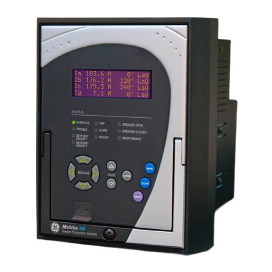
- Page 72 FRONT CONTROL PANEL INTERFACE CHAPTER 3: INTERFACES Front control panel interface Figure 3-1: 350 Feeder Protection System Front Panel - Non-programmable LEDs GE Multilin 350 Feeder Protection System TRIP BREAKER OPE I SERVICE TROUBLE ALARM BREAKER CLOSED SETPOI T PICKUP...
-
Page 73: Interfaces Front Control Panel Interface
CHAPTER 3: INTERFACES FRONT CONTROL PANEL INTERFACE Figure 3-2: 350 Feeder Protection System Front Panel - Programmable LEDs Description The relay front panel provides an interface with a liquid crystal display, LED status indicators, control keys, and a USB program port. The display and status indicators show the relay information automatically. -
Page 74: Display
FRONT CONTROL PANEL INTERFACE CHAPTER 3: INTERFACES Display The 80-character liquid crystal display (LCD) allows visibility under varied lighting conditions. When the keypad and display are not being used, system information is displayed after a user-defined period of inactivity. Pressing the Menu key during the display of default message returns the display to the last message shown before the default message appeared. - Page 75 CHAPTER 3: INTERFACES FRONT CONTROL PANEL INTERFACE When the display shows SETPOINTS, pressing the MESSAGE ► key or the ENTER key will display the page headers of programmable parameters (referred to as setpoints in the manual). When the display shows ACTUAL VALUES, pressing the MESSAGE ► key or the ENTER key displays the page headers of measured parameters (referred to as actual values in the manual).
-
Page 76: Led Status Indicators - Front Panel With Non-Programmable Leds
FRONT CONTROL PANEL INTERFACE CHAPTER 3: INTERFACES LED status indicators - Front panel with non-programmable LEDs • IN SERVICE: Green This LED will be continuously “ON”, when the relay is set to “Ready” under S1 RELAY SETUP > INSTALLATION > RELAY STATUS , and no major self-test errors have been detected. -
Page 77: Led Status Indicators - Front Panel With Programmable Leds
CHAPTER 3: INTERFACES FRONT CONTROL PANEL INTERFACE LED status indicators - Front panel with programmable LEDs • IN SERVICE: Green This LED will be continuously “ON”, when the relay is set to “Ready” under S1 RELAY SETUP > INSTALLATION > RELAY STATUS , and no major self-test errors have been detected. -
Page 78: Relay Messages
FRONT CONTROL PANEL INTERFACE CHAPTER 3: INTERFACES Relay messages Target messages Target messages are automatically displayed for any active condition on the relay such as pickups, trips, or alarms. The relay displays the most recent event first, and after 5 seconds will start rolling up the other target messages until the conditions clear and/or the RESET command is initiated. - Page 79 CHAPTER 3: INTERFACES FRONT CONTROL PANEL INTERFACE • Record the minor self-test error in the Event Recorder. Upon detection of a major problem, the relay will: • De-energize critical failure relay (Output Relay 7). • Inhibit operation of all other output relays (1 to 6). •...
-
Page 80: Flash Messages
FRONT CONTROL PANEL INTERFACE CHAPTER 3: INTERFACES Self-test Error Latched Description of How Often the Test What to do Message Target Problem is Performed Message? MAINTENANCE The ambient Every 1 hour Increase ventilation to the ALERT: High temperature is surroundings. Ambient above 80 Temperature... -
Page 81: Software Setup
CHAPTER 3: INTERFACES SOFTWARE SETUP Software setup Quick setup - Software interface • The Quick Setup window allows you to configure important settings from different screens in the relay by adding them to a common window. • Quick Setup window options are available for a single device or a file. •... -
Page 82: Enervista 3 Series Setup Software
500 MB free hard drive space (1 GB recommended) • 1024 x 768 display (1280 x 800 recommended) The EnerVista 3 Series Setup software can be installed from either the GE EnerVista CD or the GE Multilin website at http://www.gegridsolutions.com/multilin... - Page 83 CHAPTER 3: INTERFACES SOFTWARE SETUP In the EnerVista Launchpad window, click the Add Product button and select the 350 Feeder Protection System as shown below. Select the Web option to ensure the most recent software release, or select CD if you do not have a web connection, then click the Add Now button to list software items for the 350 .
- Page 84 SOFTWARE SETUP CHAPTER 3: INTERFACES If you are going to communicate from your computer to the 350 Relay using the USB port: 10. Plug the USB cable into the USB port on the 350 Relay then into the USB port on your computer.
-
Page 85: Upgrading The Software
(for USB communications) or to the RS485 terminals on the back of the device (for RS485 communications). This example demonstrates an USB connection. For RS485 communications, the GE Multilin F485 converter will be required. Refer to the F485 manual for additional details. To configure the relay for Ethernet communications, see Configuring Ethernet Communications below. -
Page 86: Using The Quick Connect Feature
SOFTWARE SETUP CHAPTER 3: INTERFACES Click the Read Order Code button to connect to the 350 device and upload the order code. Click OK when the relay order code has been received. The new device will be added to the Site List window (or Online window) located in the top left corner of the main EnerVista 3 Series Setup window. -
Page 87: Configuring Ethernet Communications
Install and start the latest version of the EnerVista 3 Series Setup Setup software NOTE (available from the GE EnerVista CD). See the previous section for the installation procedure. Click on the Device Setup button to open the Device Setup window and click the Add Site button to define a new site. -
Page 88: Connecting To The Relay
SOFTWARE SETUP CHAPTER 3: INTERFACES Enter the IP address, slave address, and Modbus port values assigned to the 350 relay (from the S1 RELAY SETUP > COMMUNICATIONS > ETHERNET menu). Click the Read Order Code button to connect to the 350 and upload the order code. If a communications error occurs, ensure that the Ethernet communication values correspond to the relay setting values. -
Page 89: Working With Setpoints And Setpoint Files
CHAPTER 3: INTERFACES SOFTWARE SETUP The Front Panel settings window opens with a corresponding status indicator on the lower left of the EnerVista 3 Series Setup window. If the status indicator is red, verify that the serial, USB, or Ethernet cable is properly connected to the relay, and that the relay has been properly configured for communications (steps described earlier). - Page 90 SOFTWARE SETUP CHAPTER 3: INTERFACES Clicking the arrow at the end of the box displays a numerical keypad interface that allows the user to enter a value within the setpoint range displayed near the top of the keypad: Click = to exit from the keypad and keep the new value. Click on X to exit from the keypad and retain the old value.
-
Page 91: Setting Programmable Leds
CHAPTER 3: INTERFACES SOFTWARE SETUP Setting Front panels with programmable LEDs have eight LEDs that are off by default, and must programmable LEDs be set to a source signal and type. Four of these LEDs can also be set to different colors. Establish communications with the relay. -
Page 92: File Support
SOFTWARE SETUP CHAPTER 3: INTERFACES Click Print to print a copy of the customized front panel label. File support Opening any EnerVista 3 Series Setup file will automatically launch the application or provide focus to the already opened application. If the file is a settings file (has a ‘SR3’ extension) which had been removed from the Settings List tree menu, it will be added back to the Settings List tree. -
Page 93: Downloading And Saving Setpoint Files
CHAPTER 3: INTERFACES SOFTWARE SETUP Downloading and Back up a copy of the in-service settings for each commissioned 350 unit, so as to revert saving setpoint files to the commissioned settings after inadvertent, unauthorized, or temporary setting changes are made, after the settings default due to firmware upgrade, or when the unit has to be replaced. -
Page 94: Creating A New Setpoint File
Discontinued order codes may be included to maintain back-compatibility of setpoint files. NOTE: For current order codes, refer to the GE Multilin website at http:// www.gegridsolutions.com/multilin. NOTE... -
Page 95: Upgrading Setpoint Files To A New Revision
1.20, change the setpoint file revision to “1.4x”. Discontinued order codes may be included to maintain back-compatibility of setpoint files. NOTE: For current order codes, refer to the GE Multilin website at http:// www.gegridsolutions.com/multilin. -
Page 96: Printing Setpoints And Actual Values
SOFTWARE SETUP CHAPTER 3: INTERFACES Printing setpoints and The EnerVista 3 Series Setup software allows the user to print partial or complete lists of actual values setpoints and actual values. Use the following procedure to print a list of setpoints: Select a previously saved setpoints file in the File pane or establish communications with a 350 device. -
Page 97: Loading Setpoints From A File
CHAPTER 3: INTERFACES SOFTWARE SETUP Loading setpoints from a file An error message will occur when attempting to download a setpoint file with a CAUTION: revision number that does not match the relay firmware. If the firmware has been upgraded since saving the setpoint file, see for instructions on changing the revision number of a setpoint file. -
Page 98: Upgrading Relay Firmware
To upgrade the 350 firmware, follow the procedures listed in this section. Upon successful completion of this procedure, the 350 will have new firmware installed with the factory default setpoints.The latest firmware files are available from the GE Multilin website at http://www.GEgridsolutions.com/multilin. - Page 99 CHAPTER 3: INTERFACES SOFTWARE SETUP The EnerVista 3 Series Setup software will notify the user when the 350 has finished loading the file. Carefully read any displayed messages and click OK to return the main screen. Cycling power to the relay is recommended after a firmware upgrade. After successfully updating the 350 firmware, the relay will not be in service and will require setpoint programming.
-
Page 100: Advanced Enervista 3 Series Setup Features
SOFTWARE SETUP CHAPTER 3: INTERFACES Advanced EnerVista 3 Series Setup features Flexcurve editor The FlexCurve Editor is designed to allow the user to graphically view and edit the FlexCurve. The Flexcurve Editor screen is shown below: • The Operate Curves are displayed, which can be edited by dragging the tips of the curves •... -
Page 101: Transient Recorder (Waveform Capture)
CHAPTER 3: INTERFACES SOFTWARE SETUP • The user can save Configured Trip Times. • The user can export Configured Trip Times to a CSV file • The user can load Trip Times from a CSV File • The screen above shows the model followed by 350 for viewing Flexcurves. Select Initialize to copy the trip times from the selected curve to the FlexCurve. - Page 102 SOFTWARE SETUP CHAPTER 3: INTERFACES DELTA TRIGGER TIME & DATE VECTOR DISPLAY SELECT CURSOR LINE POSITION Indicates time difference Indicates the cursor line position Displays the time and date Click here to open a new graph in time with respect to the between the two cursor of the Trigger.
- Page 103 CHAPTER 3: INTERFACES SOFTWARE SETUP Preference Button The following window will appear: Change the color of each graph as desired, and select other options as required, by checking the appropriate boxes. Click OK to store these graph attributes, and to close the window.
-
Page 104: Protection Summary
SOFTWARE SETUP CHAPTER 3: INTERFACES Protection summary Protection Summary is a single screen which holds the summarized information of different settings from Grouped Elements, Control Elements and Maintenance screens. Protection Summary Screen allows the user to: • view the output relay assignments for the elements •... - Page 105 CHAPTER 3: INTERFACES SOFTWARE SETUP 350 FEEDER PROTECTION SYSTEM – INSTRUCTION MANUAL 3–35...
-
Page 106: Password Security
SOFTWARE SETUP CHAPTER 3: INTERFACES Password security Password security is an optional feature of the 350 which can be setup using the EnerVista 3 Series Setup software. The password system has been designed to facilitate a hierarchy for centralized management. This is accomplished through a Master level access password which can be used for resetting lower level access passwords and higher level privileged operations. - Page 107 CHAPTER 3: INTERFACES SOFTWARE SETUP Initial setup of the Local Setpoint and Local Control passwords requires the Master Access level. If Overwrite Local Passwords is set to YES, Local passwords can be changed remotely only (over RS485 or Ethernet). If Overwrite Local Passwords is set to NO, Local passwords can be changed locally only (over USB or keypad).
- Page 108 SOFTWARE SETUP CHAPTER 3: INTERFACES 3–38 350 FEEDER PROTECTION SYSTEM – INSTRUCTION MANUAL...
-
Page 109: Actual Values
Grid Solutions 350 Feeder Protection System Chapter 4: Actual values Actual values Actual values overview All measured values, the status of digital inputs and outputs, and fault analysis information are accessed in Actual Values mode. Actual value messages are organized into logical groups for easy reference as shown below. -
Page 110: A1 Status
A1 STATUS CHAPTER 4: ACTUAL VALUES A1 Status Clock PATH: ACTUAL VALUES > A1 STATUS > CLOCK CURRENT DATE Feb 23 2016 Range: Date in format shown Indicates today’s date. CURRENT TIME 09:17:12 Range: Time in format shown Indicates the current time of day. Contact inputs PATH: ACTUAL VALUES >... -
Page 111: Logic Elements
CHAPTER 4: ACTUAL VALUES A1 STATUS OUTPUT RELAY 3 to 6 (Auxiliary Output Relays) Range: Off, On OUTPUT RELAY 7 (Critical Failure Relay) Range: Off, On The "ON" state indicates that the relay is in-service. Logic elements PATH: ACTUAL VALUES > A1 STATUS > LOGIC ELEMENTS LOGIC ELEMENT 1 to 16 Range: Off, On The state “ON”... -
Page 112: Output Relays Summary
A1 STATUS CHAPTER 4: ACTUAL VALUES C. INPUTS SUMMARY CI#6 CI#7 CI#3 CI#8 CI#4 CI#9 CI#5 CI#10 The display shows a summary of the states of all contact inputs. Output relays summary PATH: ACTUAL VALUES > A1 STATUS > OUT RELAYS SUMMARY OUTPUT RELAYS SUMMARY TRIP RLY#5... -
Page 113: Goose Hdr Status
CHAPTER 4: ACTUAL VALUES A1 STATUS GOOSE HDR status PATH: ACTUAL VALUES > A1 STATUS > GOOSE HDR STATUS GOOSE 1 TO 8 H.STATUS Range: OFF, ON Default: OFF 61850 status PATH: ACTUAL VALUES > A1 STATUS > 61850 STATUS When a CID file is sent to the relay following a configuration change, it is temporarily placed in the SCL/notvalidated directory. -
Page 114: Ieee 1588 Ptp (Precision Time Protocol)
A1 STATUS CHAPTER 4: ACTUAL VALUES • PRP_HSR B TX - This is the number of correct messages transmitted over port B. • PRP_HSR A ERR - This is the number of bad messages received over port A. • PRP_HSR B ERR - This is the number of bad messages received over port B. IEEE 1588 PTP (Precision Time Protocol) PATH: ACTUAL VALUES >... -
Page 115: A2 Metering
CHAPTER 4: ACTUAL VALUES A2 METERING A2 Metering The relay measures all RMS currents and voltages, frequency, and all auxiliary analog inputs. Other values like neutral current, symmetrical components, power factor, power (real, reactive, apparent), are derived. All quantities are recalculated every power system cycle and perform protection and monitoring functions. -
Page 116: Voltage
A2 METERING CHAPTER 4: ACTUAL VALUES PH C CURRENT 2nd HRMC 0.0 % Range: 0.0 to 100.0% Voltage Path: ACTUAL VALUES > A2 METERING > VOLTAGE AN VOLTAGE 0 V 0 Range: 0 to 65535 V BN VOLTAGE 0 V 0 Range: 0 to 65535 V CN VOLTAGE 0 V 0... -
Page 117: Power
CHAPTER 4: ACTUAL VALUES A2 METERING Path: ACTUAL VALUES > A2 METERING > VOLTAGE > VOLTS PER HERTZ Display the value in x V/H z. Power Path: ACTUAL VALUES > A2 METERING > POWER 3 ph REAL POWER 0.0 kW Range: -100000.0 to 100000.0 kW 3 ph REACTIVE POWER 0.0 kVAR... -
Page 118: Current Demand
A2 METERING CHAPTER 4: ACTUAL VALUES Current Demand The relay measures Current Demand on each phase. These parameters can be monitored to reduce supplier Demand penalties or for statistical metering purposes. Demand calculations are based on the measurement type selected under S6 MONITORING >... -
Page 119: Thermal Capacity
CHAPTER 4: ACTUAL VALUES A2 METERING APPARENT PWR DMD Range: 0.0 to 100000.0 kVA MAX APPARENT PWR DMD Range: 0.0 to 100000.0 kVA REAL PWR DMD D/T MM/DD/YY HH:MM:SS REACTIVE PWR DMD D/T MM/DD/YY HH:MM:SS APPARENT PWR DMD D/T MM/DD/YY HH:MM:SS Thermal capacity Path: ACTUAL VALUES >... -
Page 120: A3 Records
A3 RECORDS CHAPTER 4: ACTUAL VALUES A3 Records The 350 has an event recorder which runs continuously. All event records are stored in memory such that information is maintained for up to 3 days even after losing relay control power. The events are displayed from newest to oldest event. Each event has a header message containing a summary of the event that occurred, and is assigned an event number equal to the number of events that have occurred since the recorder was cleared. - Page 121 CHAPTER 4: ACTUAL VALUES A3 RECORDS E778, CONTROL BKR Stat Open 3ph APPARENT POWER 0.0 kVA ▼ E778, CONTROL BKR Stat Open POWER FACTOR 0.00 ▼ E778, CONTROL BKR Stat Open THERM CAP PH A 0.0% ▼ E778, CONTROL BKR Stat Open THERM CAP PH B 0.0% ▼...
-
Page 122: Transient Records
A3 RECORDS CHAPTER 4: ACTUAL VALUES Transient records PATH: ACTUAL VALUES > A3 RECORDS > TRANSIENT RECORDS FORCE TRIGGER? Range: No, Yes TOTAL RECORDS Range: N/A AVAILABLE RECORDS Range: N/A LAST CLEARED Feb 08 2009 Range: N/A Fault report PATH: ACTUAL VALUES >... -
Page 123: Clear Event Record
CHAPTER 4: ACTUAL VALUES A3 RECORDS BN VOLTAGE 0 V 0 CN VOLTAGE 0 V 0 AB VOLTAGE 0 V 0 BC VOLTAGE 0 V 0 CA VOLTAGE 0 V 0 NTRL VOLTAGE 0 V 0 AUX VOLTAGE 0 V 0 FREQUENCY 60.00 Hz Clear event record... -
Page 124: Clear Fault Report
A3 RECORDS CHAPTER 4: ACTUAL VALUES Clear fault report PATH: ACTUAL VALUES > A3 RECORDS > CLEAR FAULT REPORT CLEAR Range: No, Yes When set to "Yes," pressing the ENTER key will clear all fault reports. 4–16 350 FEEDER PROTECTION SYSTEM – INSTRUCTION MANUAL... -
Page 125: A4 Target Messages
CHAPTER 4: ACTUAL VALUES A4 TARGET MESSAGES A4 Target messages Target messages are automatically displayed for any active condition on the relay such as pickups, trips, alarms, or asserted input. The target messages shown in the table below are displayed as necessary. The relay displays the most recent event first, and after 5 seconds starts rolling up the other target messages, until the Reset command is initiated. - Page 126 A4 TARGET MESSAGES CHAPTER 4: ACTUAL VALUES When current greater than the IOC1 pickup level is applied, the 3350 50 display shows the following target message: A4 TARGET MESSAGES Ph IOC1 Trip STATE: PKP After the 200 ms time delay expires, the display shows the following message only: A4 TARGET MESSAGES Ph IOC1 Trip STATE: OP...
-
Page 127: Quick Setup - Front Control Panel
Grid Solutions 350 Feeder Protection System Chapter 5: Quick setup - Front control panel Quick setup - Front control panel The “Quick Setup” utility is part of the 350 relay main menu, and can be used for quick and easy programming. Power system parameters, and settings for some simple over-current elements can be easily set. -
Page 128: Quick Setup Settings
QUICK SETUP SETTINGS CHAPTER 5: QUICK SETUP - FRONT CONTROL PANEL Quick Setup settings The setpoints below can be programmed under the "Quick Setup" menu. Note that monitoring of Breaker Status via 52a, 52b, or both of these contacts,, should be programmed under SETPOINTS >... - Page 129 CHAPTER 5: QUICK SETUP - FRONT CONTROL PANEL QUICK SETUP SETTINGS GND TOC FUNCTION Range: Disabled, Trip, Latched Alarm, Alarm Default: Disabled ↘ GND TOC PICKUP Range: 0.05 to 20.00 x CT Default: 1.00 x CT GND TOC CURVE Range: ANSI Extremely/Very/Moderately/Normally Inverse; Definite Time;...
- Page 130 QUICK SETUP SETTINGS CHAPTER 5: QUICK SETUP - FRONT CONTROL PANEL PH IOC1 FUNCTION Range: Disabled, Trip, Latched Alarm, Alarm Default: Disabled ↘ PH IOC1 PICKUP Range: 0.05 to 20.00 x CT Default: 1.00 x CT GND IOC1 FUNCTION Range: Disabled, Trip, Latched Alarm, Alarm Default: Disabled ↘...
-
Page 131: Setpoints Setpoints Main Menu
Grid Solutions 350 Feeder Protection System Chapter 6: Setpoints Setpoints Setpoints Main Menu The 350 has a considerable number of programmable setpoints, all of which make the relay extremely flexible. These setpoints have been grouped into a variety of pages and subpages as shown below. - Page 132 SETPOINTS MAIN MENU CHAPTER 6: SETPOINTS Figure 6-1: Setpoints main menu SETPOINTS S1 RELAY SETUP S1 RELAY SETUP S2 SYSTEM SETUP CLOCK S3 PROTECTION PASSWORD SECURITY COMMUNICATIONS S4 CONTROLS S5 INPUTS/OUTPUTS EVENT RECORDER S6 MONITORING TRANSIENT RECDR FAULT REPORT FRONT PANEL INSTALLATION S2 SYSTEM SETUP CURRENT SENSING...
-
Page 133: Setpoint Entry Methods
Files can be stored and downloaded for fast, error free entry when a computer is used. To facilitate this process, the GE EnerVista CD with the EnerVista 3 Series Setup software is supplied with the relay. -
Page 134: Logic Diagrams
SETPOINTS MAIN MENU CHAPTER 6: SETPOINTS : “Control” the feature is operational. When an output <ELEMENT_NAME> FUNCTION is generated, the feature operates any selected output relays. The “Trip”, “Alarm”, and “Control” function setpoint values are also used to select those operations that will be stored in the Event Recorder. -
Page 135: Setting Text Abbreviations
CHAPTER 6: SETPOINTS SETPOINTS MAIN MENU • Logic: Described with basic logic gates (AND, OR, XOR, NAND, NOR). The inverter (logical NOT), is shown as a circle: ○. Setting text abbreviations The following abbreviations are used in the setpoints pages. •... -
Page 136: S1 Relay Setup
S1 RELAY SETUP CHAPTER 6: SETPOINTS S1 Relay setup Figure 6-2: Relay Setup menu S1 RELAY SETUP CLOCK PASSWORD SECURITY COMMUNICATIONS EVENT RECORDER TRANSIENT RECDR FAULT REPORT FRONT PANEL INSTALLATION 898764A4.cdr Clock The 350 relay has an internal real time clock that performs time stamping via IRIG-B for various features such as the event and transient recorders. - Page 137 CHAPTER 6: SETPOINTS S1 RELAY SETUP DLS ENABLE Range: Disabled, Enabled Default: Disabled PATH: SETPOINTS > S1 RELAY SETUP > CLOCK > DLS ENABLE [ENABLED] DLS START MONTH: Range: Not Set, January, February, March, April, May, June, July, August, September, October, November, December Default: Not Set This setting sets the month for the DLS start time.
-
Page 138: 350 Real Time Clock
S1 RELAY SETUP CHAPTER 6: SETPOINTS SNTP MODE: Range: Disabled, Unicast, Anycast, Broadcast Default: Disabled When “Disabled” is selected for this setting, SNTP time synchronization is disabled. SNTP PORT: Range: 0 to 65535 Default: 0 This setting configures the port that 350 .is using. SNTP SERVER IP ADR: Range: Standard IP Address format Default: 000.000.000.000... -
Page 139: Password Security
CHAPTER 6: SETPOINTS S1 RELAY SETUP PTP VLAN PRIORITY Range: 0 to 7 Default: 4 The setting selects the value of the priority field in the 802.1Q VLAN tag in request messages issued by the relay’s peer delay mechanism. In compliance with PP (Power Profile) the default VLAN priority is 4, but it is recommended that in accordance with PTP it be set to 7. -
Page 140: Access Passwords
S1 RELAY SETUP CHAPTER 6: SETPOINTS passwords (USB port and keypad), or remotely using the Remote passwords (RS485 and Ethernet ports). The user can have either Setpoint or Control Level access active, but not both simultaneously from the same interface. Setpoint and Control passwords must be 3 to 10 alphanumeric characters in length. - Page 141 CHAPTER 6: SETPOINTS S1 RELAY SETUP Figure 6-3: Menu for handling password security using keypad S1 PASSWORD SECURITY LOC SETPOINTS PSWD S1 LOC SETPOINTS PSWD LOC CONTROLS PSWD ENTER OLD PASSWORD PSWD FOR RESET KEY ENTER NEW PASSWORD CONFIRM NEW PASSWORD S1 LOC CONTROLS PSWD ENTER OLD PASSWORD ENTER NEW PASSWORD...
-
Page 142: Communications
S1 RELAY SETUP CHAPTER 6: SETPOINTS Communications Figure 6-4: Main communications menu S1 COMMUNICATIONS RS485 ETHERNET MODBUS PROTOCOL IEC 60870-5-103 IEC 60870-5-104* DNP PROTOCOL GOOSE CONFIGURATION** OPC-UA*** * Available with Comms Order Code 1 ** Available with Comms Order Code 3, 4, 5 *** Available with Comms Order Code 4, 5 898766A5.cdr RS485 interface... -
Page 143: Redundancy Mode
CHAPTER 6: SETPOINTS S1 RELAY SETUP SUBNET IP MASK Range: Standard IP Address format Default: 255.255.252.0 This setting specifies the Subnet IP Mask setting for the Ethernet port. GATEWAY IP ADDRESS Range: Standard IP Address format Default: 000.000.000.000 This setting specifies the Gateway IP Address for the Ethernet port. CONNECTION TYPE Range: Copper, fiber Default: Copper... -
Page 144: Modbus
S1 RELAY SETUP CHAPTER 6: SETPOINTS LLA PRIORITY Range: Enabled, Disabled Default: Enabled This setting is only used when REDUNDANCY is set to LLA. If this setting is set to ENABLED, Port A has priority. If the Port A LLA detects a problem with the link, communication is switched to Port B. -
Page 145: Iec60870-5-104 Protocol
CHAPTER 6: SETPOINTS S1 RELAY SETUP MODBUS SLAVE ADDRESS Range: 1 to 254 in steps of 1 Default: 254 This setting specifies the Modbus slave address . Each device must have a unique address from 1 to 254. Address 0 is the broadcast address to which all Modbus slave devices listen. -
Page 146: Dnp Communication
S1 RELAY SETUP CHAPTER 6: SETPOINTS DNP communication Figure 6-8: DNP communication settings PATH: SETPOINTS > RELAY SETUP > COMMUNICATIONS > DNP PROTOCOL > DNP GENERAL Please refer to the 3 Series Communications Guide for details on how to set up the DNP protocol. -
Page 147: Opc-Ua Settings
CHAPTER 6: SETPOINTS S1 RELAY SETUP Figure 6-9: EnerVista 3 Series GOOSE General Settings OPC-UA Settings OPCUA Enable Range: Disabled, Enabled Default: Disabled The OPCUA Enable setting is only for a 350 relay with a communications Order Code 4. In this case only, the OPC-UA and the IEC61850 protocol do not run simultaneously. If IEC61850 is running by default but it is desired to use OPC-UA instead, the user must put the OPCUA Enable setting to Enabled. -
Page 148: Event Recorder
S1 RELAY SETUP CHAPTER 6: SETPOINTS Event recorder The Event Recorder runs continuously, capturing and storing the last 256 events. All events are stored in a non-volatile memory where the information is maintained for up to 3 days in case of lost relay control power. PATH : SETPOINTS >... -
Page 149: Transient Recorder
CHAPTER 6: SETPOINTS S1 RELAY SETUP VIRTUAL INPUTS Range: Disabled, Enabled Default: Enabled When set to “Enabled”, the event recorder records the events, which occur upon state changes of any logic element. REMOTE INPUTS Range: Disabled, Enabled Default: Enabled When set to “Enabled”, the event recorder records the events, which occur upon state change of any programmed remote input. - Page 150 S1 RELAY SETUP CHAPTER 6: SETPOINTS TRIGGER ON PKP Range: Off, On Default: Off Selection of “Yes” setting enables triggering for the recorder upon Pickup condition detected from any protection or control element. TRIGGER ON DPO Range: Off, On Default: Off Selection of “Yes”...
-
Page 151: Fault Report
CHAPTER 6: SETPOINTS S1 RELAY SETUP Fault report The 350 relay has a Fault Report which captures measured analog signals at the time of the trip. The Fault Report stores only the last recorded values in relay's non-volatile memory. The Fault Report has two configurable setpoints, "FAULT TRIGGER" and "DELAY OTHER TRIGGERS". -
Page 152: Front Panel With Non-Programmable Leds
S1 RELAY SETUP CHAPTER 6: SETPOINTS Front panel with non-programmable LEDs The user can send a message to the display, that will override any normal message by sending text through Modbus. Refer to the 3 Series Communications Guide for register details. - Page 153 CHAPTER 6: SETPOINTS S1 RELAY SETUP STATUS IN SERVICE LED 1 LED 5 TROUBLE LED 2 LED 6 LED 3 LED 7 TRIP ALARM LED 4 LED 8 898862A1.CDR Programmable LEDs can be configured using the keypad or the EnerVista 3 Series Setup software as described in Chapter 3 - Software Setup.
-
Page 154: Installation
S1 RELAY SETUP CHAPTER 6: SETPOINTS LED5(8) COLOR Range: Off, Red, Orange, Green Default: Orange Selects the color of programmable LED 5 through 8. Note that programmable LEDs 1 through 4 have fixed colors: LED1 (Red), LED2 (Orange), NOTE: LED3 (Orange), LED4 (Orange). NOTE Figure 6-10: Programmable LED with Trigger SOURCE and Self-reset or Latched TYPE Command... -
Page 155: S2 System Setup
CHAPTER 6: SETPOINTS S2 SYSTEM SETUP S2 System Setup Figure 6-11: Main system setup menu Current sensing PATH: SETPOINTS > S2 SYSTEM SETUP > CURRENT SENSING PHASE CT PRIMARY Range: 1 A to 6000 A Default: 500 A Enter the primary rating of the three-phase feeder CTs wired to the relay phase CT terminals (see above). -
Page 156: Voltage Sensing
S2 SYSTEM SETUP CHAPTER 6: SETPOINTS Voltage sensing PATH: SETPOINTS > S2 SYSTEM SETUP > VOLTAGE SENSING VT CONNECTION Range: Wye, Delta Default: Wye The 350 provides three-phase VT inputs, that can be wired to either bus VTs or feeder VTs. - Page 157 CHAPTER 6: SETPOINTS S2 SYSTEM SETUP Figure 6-12: Broken delta connection 898856A1.cdr AUX VT SECONDARY Range: 50 V to 240 V Default: 110 V This setting defines the voltage across the VT secondary winding when nominal voltage is applied to the primary. On a source of 13.8kV line-line voltage, with a VT ratio of 14400:120 V delta connection, the voltage to be entered is “115 V”.
-
Page 158: Power System
S2 SYSTEM SETUP CHAPTER 6: SETPOINTS Power system PATH: SETPOINTS > S2 SYSTEM SETUP > POWER SYSTEM NOMINAL FREQUENCY Range: 60 Hz, 50 Hz Default: 60 Hz Enter the nominal power system frequency. This value is used as a default to set the optimal digital sampling rate. -
Page 159: User Curve
CHAPTER 6: SETPOINTS S2 SYSTEM SETUP Table 6-1: Breaker open / Breaker closed status logic 52a contact 52b contact Breaker status configured configured Open Close 52a contact open 52a contact closed 52b contact closed 52b contact open 52a contact open 52a contact closed 52b contact closed 52b contact open... -
Page 160: Flexcurves
S2 SYSTEM SETUP CHAPTER 6: SETPOINTS FlexCurves There are two user-programmable FlexCurves™ available with the 350 system, labeled A and B. For details on FlexCurves please refer to S3 Protection/TOC Curves in this manual. The User Curve and Flexcurves A and B are available for programming under EnerVista NOTE: 3 Series Setup software. -
Page 161: S3 Protection
CHAPTER 6: SETPOINTS S3 PROTECTION S3 Protection The 350 protection elements are organized in two identical setpoint groups: Setpoint Group 1 and Setpoint Group 2. Figure 6-14: Main Protection menu S3 SETPOINT GROUP 1/2 PHASE TOC PHASE IOC PHASE DIR OC GROUND TOC GROUND IOC GROUND DIR OC... - Page 162 I / Ipu > 1. Select the appropriate curve shape and multiplier, thus matching the appropriate curve with the protection requirements. The available curves are shown in the table below. ANSI GE TYPE IAC OTHER Extremely Inverse Extremely Inverse...
- Page 163 CHAPTER 6: SETPOINTS S3 PROTECTION Table 6-3: ANSI Curve Constants ANSI Curve Shape ANSI Extremely Inverse 0.0399 0.2294 0.5000 3.0094 0.7222 ANSI Very Inverse 0.0615 0.7989 0.3400 –0.2840 4.0505 ANSI Normally Inverse 0.0274 2.2614 0.3000 –4.1899 9.1272 ANSI Moderately Inverse 0.1735 0.6791 0.8000...
- Page 164 S3 PROTECTION CHAPTER 6: SETPOINTS For European applications, the relay offers the four standard curves defined in IEC 255-4 and British standard BS142. These are defined as IEC Curve A, IEC Curve B, IEC Curve C, and Short Inverse. The formulae for these curves are: where: T = trip time (seconds), M = multiplier setpoint, I = input current, I = pickup current setpoint, K, E = constants.
- Page 165 The curves for the General Electric type IAC relay family are derived from the formulae: where: T = trip time (seconds), M = multiplier setpoint, I = input current, I = pickup current setpoint, A to E = constants. Table 6-7: GE Type IAC Inverse Curve Constants IAC Curve Shape IAC Extreme Inverse 0.0040 0.6379...
- Page 166 S3 PROTECTION CHAPTER 6: SETPOINTS Multiplier (TDM) 10.0 0.072 0.047 0.035 0.031 0.028 0.027 0.026 0.026 0.025 0.025 0.143 0.095 0.070 0.061 0.057 0.054 0.052 0.051 0.050 0.049 0.286 0.190 0.140 0.123 0.114 0.108 0.105 0.102 0.100 0.099 0.573 0.379 0.279 0.245 0.228...
- Page 167 CHAPTER 6: SETPOINTS S3 PROTECTION Figure 6-15: USER curve configuration settings Flexcurves Prospective FlexCurves™ can be configured from a selection of standard curves to provide the best approximate fit, then specific data points can be edited afterwards. Click the Initialize button to populate the pickup values with the points from the curve specified by the "Select Curve"...
- Page 168 S3 PROTECTION CHAPTER 6: SETPOINTS Figure 6-16: Flexcurve™ configuration settings The following settings are available for each custom Flexcurve™. Select Curve Range: ANSI Moderately Inverse, ANSI Very Inverse, ANSI Extremely Inverse, IEEE Normally Inverse, IEC Curve A, IEC Curve B, IEC Curve C, IEC Short Inverse, IAC Extreme Inv, IAC Very Inverse, IAC Inverse, IAC Short Inverse, User Curve, FlexCurve B (Note: For FlexCurve A, you can select FlexCurve B as the setpoint, and vice versa for FlexCurve B.) Default: Extremely Inverse...
- Page 169 CHAPTER 6: SETPOINTS S3 PROTECTION Multiply Range: 0.01 to 30.00 in steps of 0.01 Default: 1.00 This setting provides selection for Time Dial Multiplier by which the times from the inverse curve are modified. For example if an ANSI Extremely Inverse curve is selected with TDM = 2, and the fault current was 5 times bigger than the PKP level, the operation of the element will not occur before a time elapse of 495 ms from pickup.
-
Page 170: Phase Timed Overcurrent (51P)
S3 PROTECTION CHAPTER 6: SETPOINTS Phase timed overcurrent (51P) The relay has one Phase Time Overcurrent protection element per protection group. The settings of this function are applied to each of the three phases to produce trip or pickup per phase. The TOC pickup flag is asserted, when the current on any phase is above the PKP value. - Page 171 CHAPTER 6: SETPOINTS S3 PROTECTION PH TOC DIRECTION Range: Disabled, Forward, Reverse Default: Disabled This setting provides control to the Phase TOC function in terms of permitting operation upon fault conditions in the selected current flow direction, and blocking it when faults occur in the opposite direction.
- Page 172 S3 PROTECTION CHAPTER 6: SETPOINTS Figure 6-17: Phase time overcurrent protection logic diagram 6–42 350 FEEDER PROTECTION SYSTEM – INSTRUCTION MANUAL...
-
Page 173: Phase Instantaneous Overcurrent Protection (50P)
CHAPTER 6: SETPOINTS S3 PROTECTION Phase instantaneous overcurrent protection (50P) The 350 relay has two identical phase instantaneous overcurrent protection types per Setpoint Group: Phase IOC1, and Phase IOC2. Each consists of three separate instantaneous overcurrent elements; one per phase, with identical settings. The following path is available using the keypad. - Page 174 S3 PROTECTION CHAPTER 6: SETPOINTS Figure 6-18: Phase instantaneous overcurrent protection logic diagram 6–44 350 FEEDER PROTECTION SYSTEM – INSTRUCTION MANUAL...
-
Page 175: Phase Directional (67P)
CHAPTER 6: SETPOINTS S3 PROTECTION Phase directional (67P) The Phase Directional element (one for each of phases A, B and C) is used to discriminate between faults that occur in the forward direction, and faults that occur in the reverse direction. - Page 176 S3 PROTECTION CHAPTER 6: SETPOINTS PH DIR FUNCTION Range: Disabled, Alarm, Latched Alarm, Control Default: Disabled When Alarm function is selected, the alarm LED will flash upon detection of Reverse direction for any phase, and will drop out when the direction changes to Forward for all phases.
- Page 177 CHAPTER 6: SETPOINTS S3 PROTECTION Figure 6-20: Phase directional logic diagram 350 FEEDER PROTECTION SYSTEM – INSTRUCTION MANUAL 6–47...
-
Page 178: Ground/Sensitive Ground Timed Overcurrent Protection (51G/Sg)
S3 PROTECTION CHAPTER 6: SETPOINTS Ground/Sensitive Ground timed overcurrent protection (51G/SG) The relay has one Ground Time Overcurrent protection per setpoint group. The settings of this function are applied to the ground input current to produce trip or pickup flags. The Ground TOC pickup flag is asserted, when the ground current is above the PKP value. - Page 179 CHAPTER 6: SETPOINTS S3 PROTECTION GND TOC RESET Range: Instantaneous, Linear Default: Instantaneous The “Instantaneous” reset method is intended for applications with other relays, such as most static relays, which set the energy capacity directly to zero when the current falls below the reset threshold.
- Page 180 S3 PROTECTION CHAPTER 6: SETPOINTS Figure 6-21: Ground/Sensitive Ground timed overcurrent protection: Logic Diagram 6–50 350 FEEDER PROTECTION SYSTEM – INSTRUCTION MANUAL...
-
Page 181: Ground/Sensitive Ground Instantaneous Overcurrent Protection (50G/Sg)
CHAPTER 6: SETPOINTS S3 PROTECTION Ground/Sensitive Ground instantaneous overcurrent protection (50G/SG) The relay has one Ground/Sensitive Ground Instantaneous Overcurrent protection element per setpoint group. The settings of these functions are applied to the gound/sensitive ground current for pickup and trip flags. The Ground IOC pickup flag is asserted, when the ground current is above the PKP value. - Page 182 S3 PROTECTION CHAPTER 6: SETPOINTS Figure 6-22: Ground/Sensitive Ground instantaneous overcurrent protection logic diagram 6–52 350 FEEDER PROTECTION SYSTEM – INSTRUCTION MANUAL...
-
Page 183: Ground Directional (67G/Sg)
CHAPTER 6: SETPOINTS S3 PROTECTION Ground directional (67G/SG) The Ground Directional element is used to discriminate whether a fault occurs in a forward or in a reverse direction, and it can be used either individually or as a part of the Ground Time, or Instantaneous over-current elements. - Page 184 S3 PROTECTION CHAPTER 6: SETPOINTS Figure 6-23: Open Delta VT connection The fault is detected in the Forward direction when the direction of the operating current Ig is within ± 90° of the polarizing signal. Otherwise the direction is detected as Reverse. In the case where the voltage drops below the setting of the minimum polarizing voltage, the ground directional element is undefined.
- Page 185 CHAPTER 6: SETPOINTS S3 PROTECTION The following path is available using the keypad. For instructions on how to use the keypad, please refer to Chapter 3 - Working with the Keypad. PATH: SETPOINTS > S3 PROTECTION > SETPOINT GROUP 1(2) > GND DIR GND (S.GND) DIR FUNCTION Range: Disabled, Latched Alarm, Alarm, Control Default: Disabled...
- Page 186 S3 PROTECTION CHAPTER 6: SETPOINTS MIN POL VOLTAGE Range: 0.05 to 1.25 x VT in steps of 0.01 Default: 0.05 x VT The minimum zero sequence voltage level must be selected to prevent operation due to normal system unbalances, or voltage transformer errors. Set the minimum zero sequence voltage level to 2% of VT for well balanced systems, and 1% of VT accuracy.
- Page 187 CHAPTER 6: SETPOINTS S3 PROTECTION Figure 6-24: Ground directional logic diagram 350 FEEDER PROTECTION SYSTEM – INSTRUCTION MANUAL 6–57...
-
Page 188: Neutral Timed Overcurrent (51N)
S3 PROTECTION CHAPTER 6: SETPOINTS Neutral timed overcurrent (51N) The relay has one Neutral Time Overcurrent protection element per setpoint group. The settings of this function are applied to the calculated neutral current to produce pickup and trip flags. The Neutral TOC pickup flag is asserted, when the neutral current is above the PKP value. - Page 189 CHAPTER 6: SETPOINTS S3 PROTECTION NTRL TOC DIRECTION Range: Disabled, Forward, Reverse Default: Disabled This setting provides control to the Neutral TOC function in terms of permitting operation under fault conditions in the selected current flow direction, and blocking it when faults occur in the opposite direction.
- Page 190 S3 PROTECTION CHAPTER 6: SETPOINTS Figure 6-25: Neutral Timed Overcurrent Protection: Logic Diagram 6–60 350 FEEDER PROTECTION SYSTEM – INSTRUCTION MANUAL...
-
Page 191: Negative Sequence Timed Overcurrent Protection (51_2)
CHAPTER 6: SETPOINTS S3 PROTECTION Negative sequence timed overcurrent protection (51_2) The 3 Series relay has one Negative Sequence Overcurrent element per setpoint group. The negative sequence overcurrent protection responds to negative sequence |I |current, where it is calculated as . The negative sequence overcurrent elements are uniquely suited to detect phase-phase faults and are not sensitive to balanced loads. - Page 192 S3 PROTECTION CHAPTER 6: SETPOINTS NEG SEQ TOC RESET Range: Instantaneous, Linear Default: Instantaneous The reset of the negative sequence timed overcurrent can be selected as either “Instantaneous” or “Linear”. If Instantaneous reset is selected, the Negative Sequence TOC element will reset instantaneously providing that the current drops below 97-98% of the Neg.
- Page 193 CHAPTER 6: SETPOINTS S3 PROTECTION Figure 6-26: Negative Sequence Timed Overcurrent logic diagram 350 FEEDER PROTECTION SYSTEM – INSTRUCTION MANUAL 6–63...
-
Page 194: Neutral Instantaneous Overcurrent Protection (50N)
S3 PROTECTION CHAPTER 6: SETPOINTS Neutral instantaneous overcurrent protection (50N) The relay has two Instantaneous Overcurrent protection elements per setpoint group. The settings of this function are applied to the calculated neutral current for pickup and trip flags. The Neutral IOC pickup flag is asserted, when the neutral current is above the PKP value. - Page 195 CHAPTER 6: SETPOINTS S3 PROTECTION Figure 6-27: Neutral Instantaneous Overcurrent Protection: Logic Diagram 350 FEEDER PROTECTION SYSTEM – INSTRUCTION MANUAL 6–65...
-
Page 196: Neutral Directional (67N)
S3 PROTECTION CHAPTER 6: SETPOINTS Neutral directional (67N) The Neutral Directional element is used to discriminate between faults that occur in the forward direction, and faults that occur in the reverse direction. The Neutral Directional element can be used either individually for control or alarm by energizing the auxiliary output relays, or as a part of the Neutral, Instantaneous, or Time over-current elements to define the tripping direction. - Page 197 CHAPTER 6: SETPOINTS S3 PROTECTION The diagram below shows the regions for detection of neutral current Forward and Reverse directions with respect to the zero sequence voltage and the selected Maximum Torque Angle (MTA). When “Dual” polarizing is selected, the Reverse direction is declared if both directional comparators - the one based on the zero sequence polarizing voltage, and the other based on measured ground polarizing current - declare Reverse direction.
- Page 198 S3 PROTECTION CHAPTER 6: SETPOINTS Directional type Current direction Voltage direction Result Dual Undefined Undefined Undefined Undefined Undefined Undefined Undefined Undefined Undefined The following path is available using the keypad. For instructions on how to use the keypad, please refer to Chapter 3 - Working with the Keypad. PATH: SETPOINTS >...
- Page 199 CHAPTER 6: SETPOINTS S3 PROTECTION BLK OC DIR UN Range: Disabled, Enabled Default: Enabled This setting establishes the procedure under undefined direction conditions. If enabled, OC elements with a “Forward” or “Reverse” setting are blocked; otherwise, they are not. OUTPUT RELAY X For details see Common setpoints.
- Page 200 S3 PROTECTION CHAPTER 6: SETPOINTS Figure 6-29: Neutral directional logic diagram 6–70 350 FEEDER PROTECTION SYSTEM – INSTRUCTION MANUAL...
-
Page 201: Negative Sequence Instantaneous Overcurrent (50_2)
CHAPTER 6: SETPOINTS S3 PROTECTION Negative sequence instantaneous overcurrent (50_2) The 350 relay has one Negative Sequence Overcurrent element per protection group. The negative sequence over-current protection responds to negative sequence current, where it is calculated as . The negative sequence over-current elements are uniquely suited to detect phase-phase faults and are not sensitive to balanced loads. - Page 202 S3 PROTECTION CHAPTER 6: SETPOINTS Figure 6-30: Negative sequence instantaneous overcurrent protection logic diagram 6–72 350 FEEDER PROTECTION SYSTEM – INSTRUCTION MANUAL...
-
Page 203: Phase Undervoltage (27P)
CHAPTER 6: SETPOINTS S3 PROTECTION Phase undervoltage (27P) • Undervoltage Protection: For voltage sensitive loads, such as induction motors, a drop in voltage will result in an increase in the drawn current, which may cause dangerous overheating in the motor. The undervoltage protection feature can be used to either cause a trip or generate an alarm when the voltage drops below a specified voltage setting for a specified time delay. - Page 204 S3 PROTECTION CHAPTER 6: SETPOINTS PH UV PKP Range: 0.00 to 1.25 x VT in steps of 0.01 Default: 0.75 x VT This setting defines the phase UV pickup level, and it is usually set to a level, below which the drawn current from voltage sensitive loads, such as induction motors may cause dangerous motor overheating conditions.
- Page 205 CHAPTER 6: SETPOINTS S3 PROTECTION Figure 6-32: Phase undervoltage logic diagram 350 FEEDER PROTECTION SYSTEM – INSTRUCTION MANUAL 6–75...
-
Page 206: Phase Overvoltage (59P)
S3 PROTECTION CHAPTER 6: SETPOINTS Phase overvoltage (59P) The phase OV protection can be used to protect voltage sensitive feeder loads and circuits against sustained overvoltage conditions. The protection can be used to either cause a trip, or generate an alarm when the voltage exceeds a specified voltage value for the specified time delay. - Page 207 CHAPTER 6: SETPOINTS S3 PROTECTION Figure 6-33: Phase Overvoltage logic diagram 350 FEEDER PROTECTION SYSTEM – INSTRUCTION MANUAL 6–77...
-
Page 208: Neutral Overvoltage (59N)
S3 PROTECTION CHAPTER 6: SETPOINTS Neutral overvoltage (59N) The relay has one Neutral Overvoltage element per protection group. This element requires the three phase Bus VTs to be Wye connected. When setting the pickup for this element, it is important to consider the error in the VT ratio, as well as the normal voltage unbalance on the system. - Page 209 CHAPTER 6: SETPOINTS S3 PROTECTION Figure 6-34: Neutral Overvoltage logic diagram 350 FEEDER PROTECTION SYSTEM – INSTRUCTION MANUAL 6–79...
-
Page 210: Negative Sequence Overvoltage (59_2)
S3 PROTECTION CHAPTER 6: SETPOINTS Negative sequence overvoltage (59_2) The relay has one Negative Sequence Overvoltage element per protection group. The negative sequence overvoltage may be used to detect the loss of one or two phases of the source, a reversed voltage phase sequence, or non-system voltage conditions. The following path is available using the keypad. - Page 211 CHAPTER 6: SETPOINTS S3 PROTECTION Figure 6-35: Negative Sequence Overvoltage logic diagram 350 FEEDER PROTECTION SYSTEM – INSTRUCTION MANUAL 6–81...
-
Page 212: Auxiliary Undervoltage (27X)
S3 PROTECTION CHAPTER 6: SETPOINTS Auxiliary undervoltage (27X) The relay has one Auxiliary Undervoltage element per setpoint group. The input for this element is the voltage from the auxiliary VT relay terminals, where a single voltage from the line is connected. The time delay characteristic can be programmed as either definite time or inverse time. - Page 213 CHAPTER 6: SETPOINTS S3 PROTECTION AUX UV FUNCTION Range: Disabled, Alarm, Latched Alarm, Trip Default: Disabled For details see Common setpoints. AUX UV PKP Range: 0.00 to 1.25 x VT in steps of 0,01 Default: 0.75 x VT This setting defines the auxiliary UV pickup level. AUX UV CURVE Range: Definite Time, Inverse Time Default: Inverse Time...
- Page 214 S3 PROTECTION CHAPTER 6: SETPOINTS Figure 6-37: Auxiliary Undervoltage logic diagram 6–84 350 FEEDER PROTECTION SYSTEM – INSTRUCTION MANUAL...
-
Page 215: Auxiliary Overvoltage (59X)
CHAPTER 6: SETPOINTS S3 PROTECTION Auxiliary overvoltage (59X) The relay has one Auxiliary Overvoltage element per protection group. The element is intended for monitoring overvoltage conditions of the auxiliary voltage input. A typical application for this element is monitoring the zero sequence voltage (3V_0) from an open corner Delta VT connection. - Page 216 S3 PROTECTION CHAPTER 6: SETPOINTS Figure 6-38: Auxiliary Overvoltage logic diagram 6–86 350 FEEDER PROTECTION SYSTEM – INSTRUCTION MANUAL...
-
Page 217: Underfrequency (81U)
CHAPTER 6: SETPOINTS S3 PROTECTION Underfrequency (81U) The relay is equipped with two Underfrequency elements per setpoint group. These elements can be used for detecting system underfrequency conditions, and be part of an automatic load shedding scheme. The need for such protection arises if during a system disturbance, an area becomes electrically isolated from the main system and suffers a generation deficiency due to the loss of either transmission or generation facilities. - Page 218 S3 PROTECTION CHAPTER 6: SETPOINTS Figure 6-39: Underfrequency logic diagram 6–88 350 FEEDER PROTECTION SYSTEM – INSTRUCTION MANUAL...
-
Page 219: Overfrequency (81O)
CHAPTER 6: SETPOINTS S3 PROTECTION Overfrequency (81O) The relay is equipped with two Overfrequency elements per setpoint group, ANSI device number 81O-1, and 81O-2. Voltage channel phase A is used for frequency measurement. The steady-state frequency of a power system is an indicator of the existing balance between generated power and the load. - Page 220 S3 PROTECTION CHAPTER 6: SETPOINTS Figure 6-40: Overfrequency logic diagram 6–90 350 FEEDER PROTECTION SYSTEM – INSTRUCTION MANUAL...
-
Page 221: Thermal Overload (49)
CHAPTER 6: SETPOINTS S3 PROTECTION Thermal Overload (49) The thermal overload protection can be applied to prevent damage to the protected cables, dry transformers, capacitor banks, or even overhead lines. Loads exceeding the load ratings of the protected equipment can, over time, degrade the insulation, and may in return lead to short circuit conditions. - Page 222 S3 PROTECTION CHAPTER 6: SETPOINTS The time to operate calculated by the formula, starts from thermal level with no load before overload occurs, meaning the equipment temperature is considered as the ambient temperature and its thermal level is considered equal to zero. Eq.
- Page 223 CHAPTER 6: SETPOINTS S3 PROTECTION HEAT TIME CONSTANT (τ Range: 3.0 to 600.0 min in steps of 0.1 min Default: 6.0 min This time constant is used to compute the thermal capacity when the thermal capacity at each time-step is greater than the one computed in the previous time-step. COOL TIME CONSTANT (τ...
- Page 224 S3 PROTECTION CHAPTER 6: SETPOINTS Figure 6-41: Thermal Overload protection logic diagram 6–94 350 FEEDER PROTECTION SYSTEM – INSTRUCTION MANUAL...
-
Page 225: Wattmetric Ground Fault (32N)
CHAPTER 6: SETPOINTS S3 PROTECTION Wattmetric ground fault (32N) The Wattmetric ground fault element, also called Wattmetric Zero-sequence Directional element, responds to power derived from zero-sequence voltage and zero-sequence current in a direction specified by the element characteristic angle. The angle can be set within all four quadrants, so the measured power can be active or reactive or some combination thereof. - Page 226 S3 PROTECTION CHAPTER 6: SETPOINTS CURRENT PICKUP Range: 0.002 to 20.000 x CT in steps of 0.001 x CT Default: 0.060 x CT This setpoint specifies the neutral current supervision level for the measurement of zero sequence power. When the CURRENT setpoint value is Measured Ig, 1 x CT is the GROUND [SENS GND] CT PRIMARY setpoint value.
- Page 227 CHAPTER 6: SETPOINTS S3 PROTECTION Figure 6-42: Wattmetric characteristic angle response POWER PICKUP DELAY Range: 0.00 to 300.00 s in steps of 0.01 s Default: 0.20 s This setpoint defines a definite time delay before the inverse time characteristic is activated.
- Page 228 S3 PROTECTION CHAPTER 6: SETPOINTS CURVE Range: Definite Time, Inverse, FlexCurve A, FlexCurve B Default: Definite Time This setpoint allows the choice of one of three methods to delay the operate signal once all the conditions are met to discriminate fault direction. The "Definite Time"...
-
Page 229: Directional Power (32)
CHAPTER 6: SETPOINTS S3 PROTECTION Figure 6-43: Wattmetric ground fault logic diagram Directional power (32) The Directional Power element responds to three-phase directional power and is designed for reverse power (32REV) and low forward power (32FWD) applications for synchronous machines or interconnections involving co-generation. The relay measures the three- phase power from either a full set of wye-connected VTs or a full-set of delta-connected VTs. - Page 230 S3 PROTECTION CHAPTER 6: SETPOINTS The element has an adjustable characteristic angle and minimum operating power as shown in the Directional Power characteristic diagram. The element responds to the following condition: Where: P and Q are active and reactive powers angle theta is the element characteristic (RCA) angles SMIN is the minimum operating power.
- Page 231 CHAPTER 6: SETPOINTS S3 PROTECTION The element drops out if the magnitude of the positive-sequence current becomes NOTE: virtually zero, that is, it drops below 0.02 x CT. Such a condition is taken as an indication that the protected equipment is disconnected. The following path is available using the keypad.
- Page 232 S3 PROTECTION CHAPTER 6: SETPOINTS Figure 6-45: Directional power logic diagram 6–102 350 FEEDER PROTECTION SYSTEM – INSTRUCTION MANUAL...
-
Page 233: Broken Conductor (I1/I2 Or 46Bc)
CHAPTER 6: SETPOINTS S3 PROTECTION Broken conductor (I1/I2 or 46BC) The Broken Conductor detection function detects a feeder broken conductor condition or a single-pole open breaker malfunction condition by checking the phase current input phasors and the I ratio. In normal and balanced load situations this ratio is zero, while in broken conductor conditions an unbalance is produced and this ratio increases. - Page 234 S3 PROTECTION CHAPTER 6: SETPOINTS PICKUP DELAY Range: 0.000 to 60.000 s in steps of 0.001 s Default: 20.000 s This setting specifies the pickup time delay for this function to operate after broken conductor pickup. The time delay should be programmed to a sufficient length to ensure coordination with external fault clearing and with the dead time of any single-phase reclosers.
- Page 235 CHAPTER 6: SETPOINTS S3 PROTECTION Figure 6-46: Broken conductor logic diagram 350 FEEDER PROTECTION SYSTEM – INSTRUCTION MANUAL 6–105...
-
Page 236: Positive Sequence Undervoltage (27_1)
S3 PROTECTION CHAPTER 6: SETPOINTS Positive sequence undervoltage (27_1) The relay has one Positive Sequence Undervoltage element per protection group. The input for this element is the computed positive sequence voltage based on measured three- phase voltages at relay terminals. The time delay characteristic can be programmed as either definite time, or inverse time. - Page 237 CHAPTER 6: SETPOINTS S3 PROTECTION POS SEQ UV FUNCTION Range: Disabled, Alarm, Latched Alarm, Trip Default: Disabled For details see Common setpoints. POS SEQ UV PKP Range: 0.00 to 1.25 x VT in steps of 0,01 Default: 0.75 x VT This setting defines the positive sequence UV pickup level.
- Page 238 S3 PROTECTION CHAPTER 6: SETPOINTS Figure 6-48: Positive sequence undervoltage logic diagram 6–108 350 FEEDER PROTECTION SYSTEM – INSTRUCTION MANUAL...
-
Page 239: Volts Per Hertz (24)
CHAPTER 6: SETPOINTS S3 PROTECTION Volts per Hertz (24) Volts-per-hertz (V/Hz) protection can be applied to transformer feeders to detect overexcitation that can be dangerous for the transformer. The flux in the transformer core is directly proportional to the voltage and inversely proportional to the frequency. When V/ Hz ratios are exceeded, saturation of the magnetic core of the transformer occurs. - Page 240 S3 PROTECTION CHAPTER 6: SETPOINTS VOLTAGE MODE Range: Phase-ground, Phase-phase Default: Phase-ground If the Phase VT Connection is set to "Wye", then the Voltage Mode setting further defines the operating quantity and per-unit value for this element. When "Phase-ground" is selected, the relay applies the phase-to-ground nominal voltage programmed as VT Secondary from Voltage Sensing menu.
- Page 241 CHAPTER 6: SETPOINTS S3 PROTECTION Figure 6-49: Volts-per-hertz curves, inverse curve A Inverse Curve B: The curve for the Volts/Hertz Inverse Curve B shape is derived from the formula: where: T = Operating Time TDM = Time Delay Multiplier (delay in seconds) V = fundamental RMS value of voltage F = frequency of voltage signal Pickup = volts-per-hertz pickup setpoint...
- Page 242 S3 PROTECTION CHAPTER 6: SETPOINTS Figure 6-50: Volts-per-hertz curves, inverse curve B Inverse Curve C: The curve for the Volts/Hertz Inverse Curve C shape is derived from the formula: where: T = Operating Time TDM = Time Delay Multiplier (delay in seconds) V = fundamental RMS value of voltage F = frequency of voltage signal Pickup = volts-per-hertz pickup setpoint...
- Page 243 CHAPTER 6: SETPOINTS S3 PROTECTION Figure 6-51: Volts-per-hertz curves, inverse curve C TD MULTIPLIER Range: 0.05 to 600.00 in steps of 0.01 Default: 1.000 This setting provides a selection for Time Dial Multiplier which modifies the operating times per the selected inverse curve. When the curve is set Definite Time T(s) = TD multiplier.
- Page 244 S3 PROTECTION CHAPTER 6: SETPOINTS Figure 6-52: Volts-per-hertz logic diagram 6–114 350 FEEDER PROTECTION SYSTEM – INSTRUCTION MANUAL...
-
Page 245: S4 Controls
CHAPTER 6: SETPOINTS S4 CONTROLS S4 Controls Figure 6-53: Main controls menu S4 CONTROLS CHANGE SETP GROUP VIRTUAL INPUTS LOGIC ELEMENTS BREAKER CONTROL COLD LOAD PICKUP BREAKER FAIL CT FAILURE VT FUSE FAILURE AUTORECLOSE SYNCHROCHECK 2ND HARMONIC INHIBIT LOCKOUT 898767A5. cdr Change setpoint group The 350 relay has two identical setpoint groups- Group 1 and Group 2 for all protection elements. - Page 246 S4 CONTROLS CHAPTER 6: SETPOINTS SET GROUP 2 ACTIVE Range: Off, Contact Input 1 to 10, Virtual Input 1 to 32, Remote Input 1 to 32, Logic Elements 1 to 16, CT Fail Alarm PKP, CT Fail Alarm OP, 2nd Harmonic Alarm, 2nd Harmonic Default: Off This setting selects an input used to change from Setpoint Group 1 to Setpoint Group 2, when asserted.
- Page 247 CHAPTER 6: SETPOINTS S4 CONTROLS Figure 6-54: Switching setpoint groups - Logic diagram 350 FEEDER PROTECTION SYSTEM – INSTRUCTION MANUAL 6–117...
-
Page 248: Virtual Inputs
S4 CONTROLS CHAPTER 6: SETPOINTS Virtual inputs There are 32 virtual inputs that can be individually programmed to respond to input commands entered via the relay keypad, or by using communication protocols. PATH: SETPOINTS > S4 CONTROLS > VIRTUAL INPUTS VIRTUAL INPUT 1 Range: Off, On Default: Off... - Page 249 CHAPTER 6: SETPOINTS S4 CONTROLS LE1(16) ASSERTED Range: On, Off Default: Off This setting defines the Logic Element state “On” or “Off” to be used as an output. The asserted “On” selection provides an output “high” when the LE is "On". If asserted “Off” is selected, then the LE output will be “high”, when the LE is “Off”.
- Page 250 S4 CONTROLS CHAPTER 6: SETPOINTS BLOCK LOGIC Range: OR, AND, NOR, NAND, XOR, XNOR Default: OR This setting defines the gate type for the block inputs. A Logic Element can be used to provide under-voltage supervision when overcurrent conditions are detected. The logic from the Logic Element below, see figure: Example of Block Logic setting from EnerVista, shows that overcurrent trip will not be initiated unless the relay detects either auxiliary or phase under-voltage conditions.
- Page 251 CHAPTER 6: SETPOINTS S4 CONTROLS Figure 6-56: Logic Element logic diagram 350 FEEDER PROTECTION SYSTEM – INSTRUCTION MANUAL 6–121...
- Page 252 S4 CONTROLS CHAPTER 6: SETPOINTS Operand types and descriptions The following tables of Logic Operands, taken from Function Code FC134B in the 3 Series Communications Guide, show the list of available Logic Inputs. Where specific event descriptions are not given, a general description applies as follows: General descriptions of operands originating from protection, control, and monitoring elements: "..operand name..Trip PKP"...
- Page 253 CHAPTER 6: SETPOINTS S4 CONTROLS Element Operands Event Description General Any Trip Generated upon operation of any element with function setpoint set to "Trip" Any Alarm Generated upon operation of any element with function setpoint set to "Alarm" Any Pkp OP Generated upon detection of pickup status from any element Any Block Generated when the operation of any element is blocked...
- Page 254 S4 CONTROLS CHAPTER 6: SETPOINTS Element Operands Event Description Arc Flash Arc Flash OP Arc Flash Trip OP Arc Flash Alarm OP Arc Flash Block Light Sensor 1..4 OP Light above threshold detected by light sensor 1..4 LightSns1..4 Trbl Trouble detected in light sensor 1..4 LightSns Trbl Trouble detected in one of the light sensors or corresponding fiber HS IOC OP...
- Page 255 CHAPTER 6: SETPOINTS S4 CONTROLS Element Operands Cold Load Pickup CLP Alarm PKP CLP Alarm OP CT Failure CTFail 1 Alrm PKP CTFail 1 Alrm DPO CTFail 1 Alrm OP CTFail 1 Block Demand Curr Dmd1 Alrm OP Curr Dmd1 Block AppP Dmd Alrm OP RealP Dmd Alrm OP RealP Dmd Block...
- Page 256 S4 CONTROLS CHAPTER 6: SETPOINTS Element Operands Neutral Overvoltage Ntrl OV Trip PKP Ntrl OV2 Alrm PKP Ntrl OV3 Trip PKP Ntrl OV Trp OP Ntrl OV2 Alrm OP Ntrl OV3 Trip OP Ntrl OV Trip DPO Ntrl OV2 Alrm DPO Ntrl OV3 Trip DPO Ntrl OV Alrm PKP Ntrl OV3 Alrm PKP...
- Page 257 CHAPTER 6: SETPOINTS S4 CONTROLS Element Operands Phase Instantaneous Ph IOC1 Trip PKP Ph IOC1 Alarm PKP Ph IOC2 Trip DPO Overcurrent Ph IOC1 Trip OP Ph IOC1 Alarm OP Ph IOC1 Block Ph IOC1 Trip DPO Ph IOC1 Alarm DPO Ph IOC2 Alarm DPO Ph IOC2 Trip PKP Ph IOC2 Alarm PKP...
- Page 258 S4 CONTROLS CHAPTER 6: SETPOINTS Element Operands Phase Overvoltage Ph OV1 Trip PKP Ph OV2 Alarm PKP Ph OV3 Trip PKP Ph OV1 Trip OP Ph OV2 Alarm OP Ph OV3 Trip OP Ph OV1 Trip DPO Ph OV2 Alarm DPO Ph OV3 Trip DPO Ph OV1 Alarm PKP Ph OV2 Trip PKP...
- Page 259 CHAPTER 6: SETPOINTS S4 CONTROLS Element Operands Phase Undervoltage Ph UV1 Trip PKP Ph UV1 Alarm PKP Ph UV3 Alrm PKP Ph UV1 Trip OP Ph UV1 Alarm OP Ph UV3 Alrm OP Ph UV1 Trip DPO Ph UV1 Alarm DPO Ph UV3 Alrm DPO Ph UV2 Trip PKP Ph UV2 Alrm PKP...
- Page 260 S4 CONTROLS CHAPTER 6: SETPOINTS Element Operands Thermal Overload Therm O/L Trip OP Therm Lvl Alrm OP Therm O/L Block Therm O/L Trip DPO Therm Lvl Alrm DPO Therm PhA Alrm OP Therm PhB Alrm OP Therm PhC Alrm OP Therm PhA Alrm DPO Therm PhB Alrm DPO Therm PhC Alrm DPO...
-
Page 261: Breaker Control
CHAPTER 6: SETPOINTS S4 CONTROLS Breaker control The Breaker Control menu is designed to trip and close the breaker from the relay either remotely (LOCAL MODE setting set to "OFF," or the selected contact input deselected) or locally (the input from the LOCAL MODE setpoint asserted). While in LOCAL MODE, the REMOTE OPEN and CLOSE setpoints are not active. -
Page 262: Cold Load Pickup (Clp)
S4 CONTROLS CHAPTER 6: SETPOINTS Local Mode is set if the input for the LOCAL MODE setpoint is asserted. In this mode, the REMOTE OPEN and REMOTE CLOSE setpoints are deactivated, regardless of the status of their selected inputs. Breaker Open and Breaker Close commands from the KEYPAD BKR OPEN and KEYPAD BKR CLOSE setpoints will be active, if the breaker operation is set to Local Mode (i.e. - Page 263 CHAPTER 6: SETPOINTS S4 CONTROLS CLP BLK FUNCTION Range: Disabled, Alarm, Latched Alarm Default: Disabled For details see Common setpoints. The Alarm LED turns OFF upon manual or remote reset command. OUTAGE TIME Range: 1 to 1000 min in steps of 1 min Default: 20 min This timer starts when the feeder is de-energized (currents drop below 3% of CT nominal).
- Page 264 S4 CONTROLS CHAPTER 6: SETPOINTS Figure 6-58: Cold load pickup logic diagram 6–134 350 FEEDER PROTECTION SYSTEM – INSTRUCTION MANUAL...
-
Page 265: Breaker Failure (50Bf)
CHAPTER 6: SETPOINTS S4 CONTROLS Breaker failure (50BF) The Breaker Failure function monitors the phase currents, after a trip command from the protection elements is initiated. If any phase current is above the set current level after the BF DELAY time expires, a breaker failure will be declared, and will operate the selected output relays. - Page 266 S4 CONTROLS CHAPTER 6: SETPOINTS Figure 6-59: Breaker failure logic diagram 6–136 350 FEEDER PROTECTION SYSTEM – INSTRUCTION MANUAL...
-
Page 267: Ct Failure (60Cts)
CHAPTER 6: SETPOINTS S4 CONTROLS CT failure (60CTS) Failure of a CT secondary wiring that is open (one phase or two phases), can lead to undesired operation by some of the enabled protection elements. These include the differential protection, restricted ground fault, and sensitive overcurrent protection elements operating based on sequence components such as neutral and negative sequence instantaneous and timed over-current elements. - Page 268 S4 CONTROLS CHAPTER 6: SETPOINTS CT FAIL TIME DELAY Range: 0.00 to 60.00 s in steps of 0.01 s Default: 0.10 s This setting defines the time for CT failure to operate. Figure 6-60: CT failure detection logic diagram 6–138 350 FEEDER PROTECTION SYSTEM –...
-
Page 269: Autorecloser (79)
CHAPTER 6: SETPOINTS S4 CONTROLS Autorecloser (79) The automatic recloser is intended for use on single three-pole tripping breaker applications. Up to four reclosing “shots” can be programmed with independent set of protection elements for initiation, and individual dead time prior to each subsequent shot. A typical example for selection of individual set of overcurrent protection elements for initiation is the selection of instantaneous overcurrent protections for the first AR initiation, and selection of time overcurrent protections after the first reclose. - Page 270 S4 CONTROLS CHAPTER 6: SETPOINTS BLOCK AR For details see Common setpoints. EXT INITIATE Range: Off, Contact Input 1 to 10, Virtual Input 1 to 32, Remote Input 1 to 32, Logic Elements 1 to 16, CT Fail Alarm PKP, CT Fail Alarm OP, 2nd Harmonic Alarm, 2nd Harmonic Default: Off This setting provides selection for contact input, virtual input, remote input, or logic element to initiate the AR scheme.
- Page 271 CHAPTER 6: SETPOINTS S4 CONTROLS AR N/READY - RELAY X Range: Do not operate, Operate Default: Do Not Operate Any or all of the output relays can be selected to operate upon Autoreclose Status detected as “AR LOCKOUT”. SELECT SETP GROUP Range: Active group, SP Group 1 Active, SP Group 2 Active Default: SP Group 1 Active The Autoreclose function will be executed in the setpoint group selected as a setting in...
- Page 272 S4 CONTROLS CHAPTER 6: SETPOINTS BLOCK NTRL TOC Shot 1 to 4 Range: Off/On Default: Off If set to “On” for the selected shot, the operation of the element will initiate a breaker trip after the corresponding breaker reclosing shot. 6–142 350 FEEDER PROTECTION SYSTEM –...
- Page 273 CHAPTER 6: SETPOINTS S4 CONTROLS Figure 6-61: Autoreclose logic diagram 350 FEEDER PROTECTION SYSTEM – INSTRUCTION MANUAL 6–143...
- Page 274 S4 CONTROLS CHAPTER 6: SETPOINTS The Automatic Reclosure function is designed to perform up to four breaker autoreclosings, with a configurable dead time before each reclosing shot. Upon AR function enabled, and breaker status “closed”, the AR is set into “AR Ready” state. If an intermittent feeder fault occurs such as overhead conductor touching tree branch, one or more of the overcurrent protection elements enabled under AR initiate menu will operate and issue a breaker trip command.
-
Page 275: Synchrocheck (25)
CHAPTER 6: SETPOINTS S4 CONTROLS Synchrocheck (25) The Synchrocheck element is used for monitoring the connection of two parts of the circuit by the close of a breaker. This element verifies that voltages (VL and VB) at both sides of the breaker are within the magnitude, angle and frequency limits set by the user. - Page 276 S4 CONTROLS CHAPTER 6: SETPOINTS In order to perform the synchrocheck function, the device uses only one voltage from each end of the breaker. Voltage values to be compared must be on the same basis, either phase-to-phase or phase-to-ground voltage. Also, they must be the same at both ends of the breaker.
- Page 277 CHAPTER 6: SETPOINTS S4 CONTROLS DEAD BUS LEVEL Range: 0.00 to 1.25 x VT in steps of 0.01 x VT Default: 0.10 x VT This setting specifies the voltage level considered as the dead Bus. LIVE BUS LEVEL Range: 0.03 to 1.25 x VT in steps of 0.01 x VT Default: 0.50 x VT This setting specifies the voltage level considered as the live Bus.
- Page 278 S4 CONTROLS CHAPTER 6: SETPOINTS – Dead Line-Live Bus: the Closing permission signal is issued for a dead line and live bus Condition (without voltage at the side of the breaker that correspond to the line voltage). – Any Line-Dead Bus: the Closing permission signal is issued for any line but dead bus Condition (without voltage at the side of the breaker that correspond to the bus voltage).
- Page 279 CHAPTER 6: SETPOINTS S4 CONTROLS Figure 6-62: Synchrocheck Logic diagram 350 FEEDER PROTECTION SYSTEM – INSTRUCTION MANUAL 6–149...
-
Page 280: Second Harmonic Inhibit
S4 CONTROLS CHAPTER 6: SETPOINTS Second harmonic inhibit The 350 relay can be used for feeder transformer protection. During transformer energization, the inrush current presenting in phase currents may impact some sensitive elements, such as neutral directional overcurrent. Therefore, the ratio of the second harmonic to the fundamental magnitude per phase is monitored. - Page 281 CHAPTER 6: SETPOINTS S4 CONTROLS Figure 6-63: Second harmonic inhibit logic diagram 350 FEEDER PROTECTION SYSTEM – INSTRUCTION MANUAL 6–151...
-
Page 282: Lockout (86)
S4 CONTROLS CHAPTER 6: SETPOINTS Lockout (86) The purpose of the Lockout function is to prevent unwanted closing of the breaker after being tripped by the operation of a protection element. When triggered, the lockout maintains a constant trip signal to trip output relay #1. At the same time, the same signal is used as a block into the close output relay logic to prevent any unwanted, non-safe close commands to that relay. - Page 283 CHAPTER 6: SETPOINTS S4 CONTROLS BLOCK 1(3) For details see Common setpoints. Upon assertion of the block selected operand, lockout will not be executed. When the selected lockout blocking input drops out, and upon new trip, the trip and close output relays will be locked out.
-
Page 284: Vt Fuse Fail (Vtff Or 60Vts)
S4 CONTROLS CHAPTER 6: SETPOINTS VT fuse fail (VTFF or 60VTS) The 350 relay includes one VT Fuse Failure element. The measured voltages from the installed phase VTs are monitored and compared against user programmable levels. If one or two of the three voltages drops to less than 70% of nominal, and at the same time any of the three voltages is greater than 85%, either an Alarm or a Trip will occur after a 1 second delay. -
Page 285: Arc Flash Protection
CHAPTER 6: SETPOINTS S4 CONTROLS Arc flash protection The Arc Flash Protection module supports fast and secure protection against an arc flash event for a safe working environment. Arc Flash protection utilizes a total of four light detection fiber sensors and dedicated high- speed instantaneous overcurrent element with secure Finite Response Filtering. - Page 286 S4 CONTROLS CHAPTER 6: SETPOINTS SEAL-IN TIMER Range: 0.00 to 10.00 s Default: Enabled This timer indicates the minimum time the Arc flash trip operation state is kept raised. BLOCK For details see Common setpoints. OUTPUT RELAY X For details see Common setpoints.
- Page 287 CHAPTER 6: SETPOINTS S4 CONTROLS Figure 6-66: Arc Flash logic diagram 350 FEEDER PROTECTION SYSTEM – INSTRUCTION MANUAL 6–157...
-
Page 288: S5 Inputs/Outputs
S5 INPUTS/OUTPUTS CHAPTER 6: SETPOINTS S5 Inputs/Outputs Figure 6-67: Main inputs/outputs menu S5 INPUTS/OUTPUTS CONTACT INPUTS OUTPUT RELAYS VIRTUAL INPUTS REMOTE INPUTS 898768A2.cdr Contact inputs The 350 relay is equipped with eight (8) contact inputs, which can be used to provide a variety of functions such as for circuit breaker control, external trips, blocking of protection elements, etc. -
Page 289: Output Relays
CHAPTER 6: SETPOINTS S5 INPUTS/OUTPUTS Output relays The 350 relay is equipped with seven electromechanical output relays: two special relays designated for Breaker Trip and Close (Relay 1 “Trip”, Relay 2 “Close”), four general purpose relays (Auxiliary Relays 3 to 6), and one Critical Failure relay for fail-safe relay indication. The special purpose relays have fixed operating characteristics and the general purpose relays can be configured by the user. - Page 290 S5 INPUTS/OUTPUTS CHAPTER 6: SETPOINTS Figure 6-68: Relay 1 "TRIP" logic diagram 6–160 350 FEEDER PROTECTION SYSTEM – INSTRUCTION MANUAL...
-
Page 291: Output Relay 2 "Close"
CHAPTER 6: SETPOINTS S5 INPUTS/OUTPUTS Output Relay 2 PATH: SETPOINTS > S5 INPUTS/OUTPUTS > OUTPUT RELAYS > RELAY 2 CLOSE "Close" SEAL IN TIME Range: 0.00 to 9.99 s in steps of 0.01 Default: 0.04 s This setting defines the time to be added to the reset time of the Relay 2 Close output, thus extending its pulse width. - Page 292 S5 INPUTS/OUTPUTS CHAPTER 6: SETPOINTS Figure 6-69: Relay 2 "CLOSE" logic diagram 6–162 350 FEEDER PROTECTION SYSTEM – INSTRUCTION MANUAL...
-
Page 293: Auxiliary Output Relays 3 To 6
CHAPTER 6: SETPOINTS S5 INPUTS/OUTPUTS Auxiliary Output The 350 relay is equipped with four auxiliary output relays numbered from 3 to 6. All these Relays 3 to 6 relays are available for selection for operation of protection, control, or maintenance features. - Page 294 S5 INPUTS/OUTPUTS CHAPTER 6: SETPOINTS Output Relay 7 will be de-energized, if the relay is not IN-SERVICE or the control power is not applied to the relay Output Relay 7 will be energized when the control power is applied to the relay and the relay is IN-SERVICE mode.
- Page 295 CHAPTER 6: SETPOINTS S5 INPUTS/OUTPUTS Figure 6-71: Output relay 7: Critical Failure Relay 350 FEEDER PROTECTION SYSTEM – INSTRUCTION MANUAL 6–165...
-
Page 296: Virtual Inputs
S5 INPUTS/OUTPUTS CHAPTER 6: SETPOINTS Virtual inputs There are 32 virtual inputs that can be individually programmed to respond to input commands entered via the relay keypad, or by using communication protocols. Virtual input programming begins with enabling the Virtual Input Function, and selecting the Virtual Input Type Self-Reset or Latched under SETPOINTS >... -
Page 297: Remote Inputs
CHAPTER 6: SETPOINTS S5 INPUTS/OUTPUTS Figure 6-72: Virtual inputs scheme logic SETPOINT V INPUT FUNCTION Disabled = 0 Enabled = 1 “Virtual Input 1 to ON = 1" From Control LATCH menu ACTUAL VALUES V INPUT 1 NAME: “Virtual Input 1 to OFF = 0" (Operand) V Input 1 Status SETPOINT... -
Page 298: S6 Monitoring
S6 MONITORING CHAPTER 6: SETPOINTS S6 Monitoring Figure 6-73: Main monitoring menu S6 MONITORING DEMAND DEMAND CURRENT DMD 1 ▼ REAL PWR DMD REACTIVE PWR DMD APPARENT POWER DMD 898849A1.cdr Demand Current Demand is measured on each phase, and on three phases for real, reactive, and apparent power. -
Page 299: Current Demand
CHAPTER 6: SETPOINTS S6 MONITORING the number of blocks as set by the programmed time interval. Each new value of Demand becomes available at the end of each time interval. • Rolling Demand: This selection calculates a linear average of the quantity (RMS current, real power, reactive power, or apparent power) over the programmed Demand time interval, in the same way as Block Interval. - Page 300 S6 MONITORING CHAPTER 6: SETPOINTS Figure 6-75: Current Demand logic diagram 6–170 350 FEEDER PROTECTION SYSTEM – INSTRUCTION MANUAL...
-
Page 301: Real Power
CHAPTER 6: SETPOINTS S6 MONITORING Real Power The Real Power Demand is monitored by comparing it to a Pickup value. If the Real Power Demand Pickup is ever equalled or exceeded, the relay can be configured to cause an alarm or signal an output relay. Path: S6 MONITORING >... - Page 302 S6 MONITORING CHAPTER 6: SETPOINTS Figure 6-76: Real Power Demand logic diagram 6–172 350 FEEDER PROTECTION SYSTEM – INSTRUCTION MANUAL...
-
Page 303: Reactive Power
CHAPTER 6: SETPOINTS S6 MONITORING Reactive Power The Reactive Power Demand is monitored by comparing to a Pickup value. If the Reactive Power Demand Pickup is ever equalled or exceeded, the relay can be configured to cause an alarm or signal an output relay. Path: S6 MONITORING >... - Page 304 S6 MONITORING CHAPTER 6: SETPOINTS Figure 6-77: Reactive Power Demand logic diagram 6–174 350 FEEDER PROTECTION SYSTEM – INSTRUCTION MANUAL...
-
Page 305: Apparent Power
CHAPTER 6: SETPOINTS S6 MONITORING Apparent Power The Apparent Power Demand is monitored by comparing to a Pickup value. If the Apparent Power Demand Pickup is ever equalled or exceeded, the relay can be configured to cause an alarm or signal an output relay. Path: S6 MONITORING >... - Page 306 S6 MONITORING CHAPTER 6: SETPOINTS Figure 6-78: Apparent Power Demand logic diagram 6–176 350 FEEDER PROTECTION SYSTEM – INSTRUCTION MANUAL...
-
Page 307: Maintenance
Grid Solutions 350 Feeder Protection System Chapter 7: Maintenance Maintenance Information about the relay and the breaker can be obtained through the features included in the Maintenance page. Figure 7-1: Main maintenance menu MAINTENANCE M1 RELAY INFO M3 BKR MAINTENANCE M4 BKR MONITOR M5 RELAY MAINTENANCE M6 FACTORY SERVICE... - Page 308 M1 RELAY INFORMATION CHAPTER 7: MAINTENANCE MAIN BUILD TIME 15:57:46 This screen shows the relay Main Firmware Build Time. MAIN BOOT REVISION 1.20 This screen shows the relay Main Boot Code Revision. MAIN BOOT DATE Dec 11 2015 This screen shows the relay Main Boot Code Build Date. MAIN BOOT TIME 10:44:54 This screen shows the relay Main Boot Code Build Time.
-
Page 309: M3 Breaker Maintenance
CHAPTER 7: MAINTENANCE M3 BREAKER MAINTENANCE M3 Breaker maintenance Figure 7-2: Breaker maintenance menu M3 BKR MAINTENANCE TRIP COIL CLOSE COIL ▼ BKR TRIP COUNTER BREAKER HEALTH RESET COUNTERS 898860A1.cdr Trip coil NOTE: . The Trip coil monitoring is performed by a built-in voltage monitor on the Form A output relay: #1 Trip. - Page 310 M3 BREAKER MAINTENANCE CHAPTER 7: MAINTENANCE such connections, the trickle current will be maintained by the resistor when the breaker is open. For these applications the setting for “BYPASS BKR STATUS” should be set to ENABLED. Figure 7-4: Trip circuit with continuous monitoring DC + Trip - form A contacts External...
- Page 311 CHAPTER 7: MAINTENANCE M3 BREAKER MAINTENANCE Figure 7-5: Trip coil monitoring logic diagram 350 FEEDER PROTECTION SYSTEM – INSTRUCTION MANUAL 7–5...
-
Page 312: Close Coil
M3 BREAKER MAINTENANCE CHAPTER 7: MAINTENANCE Close coil Close coil monitoring is performed by a built-in voltage monitor on the Form A output relay: #2 Close. The voltage monitor is connected across the Form A contact, and effectively the relay detects healthy current through the circuit. To do that, an external jumper should be made between terminals “B4”, and “B5”... - Page 313 CHAPTER 7: MAINTENANCE M3 BREAKER MAINTENANCE Figure 7-7: Close Coil circuit with continuous monitoring DC + Close - form A contacts External jumper By-pass 52b contact resistor Close Coil 898793.cdr DC - The following path is available using the keypad. For instructions on how to use the keypad, please refer to Chapter 3 - Working with the Keypad.
- Page 314 M3 BREAKER MAINTENANCE CHAPTER 7: MAINTENANCE Figure 7-8: Close coil monitoring logic diagram 7–8 350 FEEDER PROTECTION SYSTEM – INSTRUCTION MANUAL...
-
Page 315: Breaker Trip Counter
CHAPTER 7: MAINTENANCE M3 BREAKER MAINTENANCE Breaker trip counter When the total number of breaker trips detected reaches the TRIP COUNTER LIMIT setpoint, an output will occur. The following path is available using the keypad. For instructions on how to use the keypad, please refer to Chapter 3 - Working with the Keypad. - Page 316 M3 BREAKER MAINTENANCE CHAPTER 7: MAINTENANCE Figure 7-9: BKR trip counter logic diagram 7–10 350 FEEDER PROTECTION SYSTEM – INSTRUCTION MANUAL...
-
Page 317: Breaker Health
CHAPTER 7: MAINTENANCE M3 BREAKER MAINTENANCE Breaker health The 350 relay provides breaker health information by monitoring and analyzing the tripping time, closing time and the spring charging time. The breaker health status depends on many factors, such as number of permissible operations, magnitude of breaking current, mechanical wear, and contact wear. - Page 318 M3 BREAKER MAINTENANCE CHAPTER 7: MAINTENANCE INCOMP TRP/CLS TIME Range: 0.00 to 600.00 s in steps of 0.01 s Default: 0.10 s This setting declares a breaker operation failure condition if the breaker does not respond within this time delay. This setting should be greater than the TRIP TIME PICKUP value and CLOSE TIME PICKUP value.
- Page 319 CHAPTER 7: MAINTENANCE M3 BREAKER MAINTENANCE LED: ALARM LATCH Set-Dominant Command RESET SETPOINTS BREAKER HEALTH FUNCTION: SETPOINTS Disabled BREAKER HEALTH Alarm ALM COUNTER LIMIT Logic Operands Latched Alarm BKR Health Alarm Alarm SETPOINTS Real Counter ≥ Alarm Counter BREAKER HEALTH Command SETPOINTS MODE:...
-
Page 320: Reset Counters
M3 BREAKER MAINTENANCE CHAPTER 7: MAINTENANCE Reset counters Reset counter commands clear various counters. PATH: MAINTENANCE > M3 RESET COUNTERS RST BKR TRIP COUNT Range: No, Yes Default: No Entering a "Yes" command will clear the Trip Counters, and an event - "Reset Trip Counter"... -
Page 321: M4 Breaker Monitor
CHAPTER 7: MAINTENANCE M4 BREAKER MONITOR M4 Breaker monitor The status of the breaker trip and close coils, as well as the trip and close circuits, can be monitored under MAINTENANCE > M4 BKR MONITOR. In the case where a breaker coil or circuit fails, the relay will display the message "Unhealthy"... -
Page 322: M5 Relay Maintenance
M5 RELAY MAINTENANCE CHAPTER 7: MAINTENANCE M5 Relay maintenance Ambient temperature The 3 Series relay has a temperature monitor feature that measures the ambient temperature around the chassis of the relay. The relay extrapolates the ambient temperature from an internal temperature sensor inside the product. This feature can be used to signal the customer that the product is being subjected to temperatures that can degrade the product life and proper action should be initiated. - Page 323 CHAPTER 7: MAINTENANCE M5 RELAY MAINTENANCE Figure 7-11: Ambient Temperature Alarm logic diagram 350 FEEDER PROTECTION SYSTEM – INSTRUCTION MANUAL 7–17...
-
Page 324: M7 Testing
M7 TESTING CHAPTER 7: MAINTENANCE M7 Testing The Test Mode for 3 Series relays consists of testing front panel LEDs and Outputs Relays The test mode state is indicated on the relay faceplate by a combination of the Maintenance LED (faceplate option E), the In-Service LED, the Trouble LED, and the critical fail relay, as shown in the following table. -
Page 325: Force Output Relays
CHAPTER 7: MAINTENANCE M7 TESTING Force output relays For testing purposes, the 350 relay provides the ability to override the normal function of the output contacts. This is done by forcing each of them to ON or OFF. The following path is available using the keypad. For instructions on how to use the keypad, please refer to Chapter 3 - Working with the Keypad. -
Page 326: General Maintenance
GENERAL MAINTENANCE CHAPTER 7: MAINTENANCE General maintenance The 350 requires minimal maintenance. As a microprocessor-based relay, its characteristics do not change over time. The expected service life of a 350 is 20 years when the environment and electrical conditions are within stated specifications. While the 350 performs continual self-tests, it is recommended that maintenance be scheduled with other system maintenance. -
Page 327: Appendix
350 Feeder Protection System Appendix Appendix Warranty For products shipped as of 1 October 2013, GE warrants most of its GE manufactured products for 10 years. For warranty details including any limitations and disclaimers, see our Terms and Conditions at https://www.gegridsolutions.com/multilin/warranty.htm For products shipped before 1 October 2013, the standard 24-month warranty applies. -
Page 328: Repairs
Customers are responsible for shipping costs to the factory, regardless of whether the unit is under warranty. • Fax a copy of the shipping information to the GE Grid Solutions service department. Use the detailed return procedure outlined at https://www.gegridsolutions.com/multilin/support/ret_proc.htm The current warranty and return information are outlined at https://www.gegridsolutions.com/multilin/warranty.htm... -
Page 329: Change Notes
CHANGE NOTES Change notes Manual Revision history Table 1: Revision History MANUAL P/N RELEASE DATE 1601-9086-A1 12 May 2009 1601-9086-A2 4 June 2009 1601-9086-A3 4 June 2009 1601-9086-A4 30 June 2009 1601-9086-A5 30 June 2009 1601-9086-A6 6 December 2010 1601-9086-A7 18 January 2011 1601-9086-A8 10 May 2010... - Page 330 CHANGE NOTES Table 2: Major Updates for 350-AN Page Number CHANGES Cover Manual revision number from AM to AN Added optical electronic device warning Chapter 1 Updated functional block diagram Updated Order Codes Added Arc Flash System Order Codes New Specifications: Arc Flash HS Phase/Ground Instantaneous Overcurrent HS 50P/50G Arc Flash Sensor Fiber Outputs: Arc Flash option...
- Page 331 CHANGE NOTES Table 4: Major Updates for 350-AL Page Number CHANGES General Changed features for 2.2x: System Setup, Ground Fault, Logic Elements, Trip Counter, Transient Recorder, VT Fuse Fail, Thermal Overload. General New features for 2.2x: Breaker Health, CT Failure Detection, Demand, Fault Reports, Directional Power, Testing, Positive Sequence UV, Lockout, Broken Conductor, Second Harmonic Inhibit, Wattmetric Ground Fault.
- Page 332 CHANGE NOTES Table 6: Major Updates for 350-AJ Page Number CHANGES Chapter 5, 6, Changed TOC PICKUP range lower value from 0.04 to 0.05 Chapter 7 Updated TIME DELAY default to 1 min General Minor corrections Table 7: Major Updates for 350-AH Page Number CHANGES Manual revision number from AG to AH...
- Page 333 Table 14: Major Updates for 350-AA Page Number CHANGES Manual revision number from A9 to AA Chapter 2 Revise Control Power parameters Table 15: Major Updates for 350-A9 Page Number CHANGES Manual revision number from A6 to A9 General Add support for additional safety/protection elements 350 FEEDER PROTECTION SYSTEM –...
- Page 334 CHANGE NOTES Table 16: Major Updates for 350-A6 Page Number CHANGES Manual revision number from A5 to A6 Chapter 1 Add Protection Elements 67G and 67N to Protection Functions Chapter 1 Add Comm option 3E to Order Code Table Chapter 7 Add Ambient Temp section (Ch 7 - Maintenance) General Increase number of Logic Elements to 16...