
Related Manuals for Ecler eGPA SERIES


Summary of Contents for Ecler eGPA SERIES
- Page 1 USER MANUAL MANUAL DE INSTRUCCIONES NOTICE D'UTILISATION BEDIENUNGSANLEITUNG eGPA SERIES...
- Page 2 Graphic Symbol Explanation The lightning flash with arrowhead symbol, within an equilateral triangle, is intended to alert the user to the presence of uninsulated “dangerous voltage” within the product’s enclosure that may be of sufficient magnitude to constitute a risk of electric shock to persons.
-
Page 3: Table Of Contents
USER MANUAL 1. IMPORTANT NOTE 1.1. Precautions 2. INTRODUCTION 2.1. Main features 3. INSTALLATION 3.1. Placement, mounting, cooling 3.2. Mains connection 3.3. Input signal connections 3.4. Power saving mode 3.5. Limiter circuit 3.6. Output connections 4. OPERATION AND USAGE 4.1. Start up 4.2. -
Page 4: Important Note
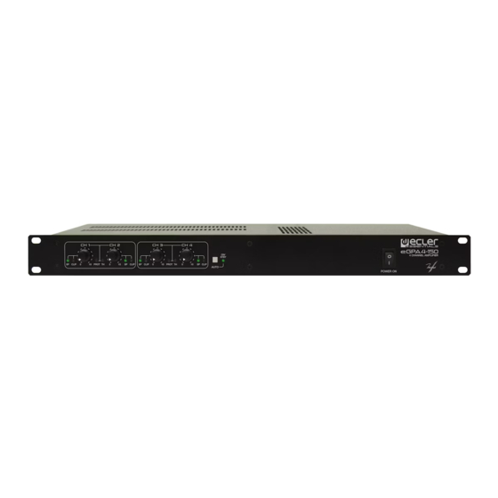
Always use shielded cables to make the connections between devices. 2. INTRODUCTION The Ecler Essentials eGPA amplifier series offers the renowned professional reliability of Ecler amplifiers at an affordable price. It consists of 4 models: with a power of 2 x 150W RMS @ 4Ω (eGPA2- 150), 4 x 150W RMS @ 4Ω... -
Page 5: Installation
3. INSTALLATION 3.1. Placement, mounting, cooling All eGPA amplifier models are presented in standard 19” rack format and are 1 unit high. It is important that the amplifier, as a heat source, is not placed next to other equipment nor exposed to high temperatures. -
Page 6: Limiter Circuit
3.5. Limiter circuit This is an extra protection always enabled in the eGPA series amplifiers. This circuit dynamically limits the input signal to avoid clipping of loud signals at the amplifier output; it automatically reduces the input level not to exceed approximately 5% distortion. -
Page 7: Indicators
4.3. Indicators eGPA amplifiers include a simple yet effective indication system. PROT/STBY indicators (7) show the absence of loudspeaker output signal. These indicators may light up for following reasons: 1. During start-up, until the STANDBY time has passed. This time period is needed for the internal operating voltages to settle. -
Page 8: Function Diagram
6. FUNCTION DIAGRAM... -
Page 9: Function List
7. FUNCTION LIST 1. SP, signal presence indicator at the CH 1 input 2. CLIP, clipping indicator for CH 1 3. SP, signal presence indicator at the CH 2 input 4. CLIP, clipping indicator for CH 2 5. CH 1 input attenuator 6. -
Page 10: Technical Characteristics
8. TECHNICAL CHARACTERISTICS 8. CARACTERÍSTICAS TÉCNICAS 8. CARACTÉRISTIQUES TECHNIQUES 8. TECHNISCHE DATEN eGPA2-150 eGPA4-150 eGPA8-150 POWER 20-20kHz 1% THD 148 WRMS 148 WRMS 148 WRMS 1 Channel @ 4Ω 74 WRMS 74 WRMS 74 WRMS 1 Channel @ 8Ω 145 WRMS 145 WRMS 144 WRMS All Channels @ 4Ω... -
Page 11: Block Diagram
9. BLOCK DIAGRAM 9. DIAGRAMA DE BLOQUES 9. SCHEMA DE BLOCS 9. BLOCKSCHALTBILD eGPA2-150 eGPA4-150... - Page 12 eGPA8-150...
- Page 13 NEEC AUDIO BARCELONA S.L. Motors 166-168, 08038 Barcelona, Spain INTERNET http://www.ecler.com 50.0300.01.00...
Need help?
Do you have a question about the eGPA SERIES and is the answer not in the manual?
Questions and answers