Sign In
Upload
Download
Table of Contents
Contents
Add to my manuals
Delete from my manuals
Share
URL of this page:
HTML Link:
Bookmark this page
Add
Manual will be automatically added to "My Manuals"
Print this page
×
Bookmark added
×
Added to my manuals
Manuals
Brands
Ecler Manuals
Amplifier
eGPA2-150
User manual
Ecler eGPA2-150 User Manual
Low impedance multichannel amplifiers
Hide thumbs
Also See for eGPA2-150
:
User manual
(13 pages)
,
User manual
(37 pages)
1
Table Of Contents
2
3
4
5
6
7
8
9
10
11
12
13
14
15
16
17
18
page
of
18
Go
/
18
Contents
Table of Contents
Bookmarks
Table of Contents
Table of Contents
Important Remark
Important Safety Instructions
Important Note
Introduction
Main Features
Installation
Placement, Mounting, Cooling
Mains Connection
Input Signal Connections
Power Saving Mode
Limiter Circuit
Output Connections
Operation and Usage
Start up
Input Attenuators
Indicators
Cleaning
Function Diagram
Function List
Technical Characteristics
Block Diagram
Advertisement
Quick Links
Download this manual
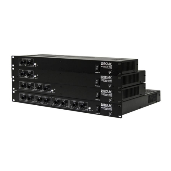
eGPA SERIES
LOW IMPEDANCE AMPLIFIERS
Multichannel amplifiers
USER MANUAL
50-0300-0109
Serie eGPA2-4-8-150 2-300
EN
Table of
Contents
Previous
Page
Next
Page
1
2
3
4
5
Advertisement
Table of Contents
Need help?
Do you have a question about the eGPA2-150 and is the answer not in the manual?
Ask a question
Questions and answers
Related Manuals for Ecler eGPA2-150
Amplifier Ecler eGPA Series User Manual
(37 pages)
Amplifier Ecler eGPA SERIES User Manual
(13 pages)
Amplifier Ecler eCA120HZ Instruction Manual
(28 pages)
Amplifier Ecler eMOTUS5P User Manual
Powered loudspeakers stereo kit (13 pages)
Amplifier Ecler eWAMPBT+ User Manual
Compact amplifiers stereo wall amplifier with media player and bt connection (16 pages)
Amplifier Ecler eHSA SERIES User Manual
High impedance amplifiers, multichannel amplifier (13 pages)
Amplifier Ecler eHSA4-150 User Manual
High impedance amplifiers, multichannel amplifier (13 pages)
Amplifier Ecler eHSA2-150 User Manual
High impedance amplifiers, multichannel amplifier (13 pages)
Amplifier Ecler eHSA2-250 User Manual
High impedance amplifiers, multichanel (15 pages)
Amplifier Ecler eHSA2-500 User Manual
High impedance amplifiers, multichanel (15 pages)
Amplifier Ecler eHSA4-500 User Manual
High impedance amplifiers, multichanel (15 pages)
Amplifier Ecler eHSA4-250 User Manual
High impedance amplifiers, multichanel (15 pages)
Amplifier Ecler eHMA Series User Manual
Mixing amplifiers (20 pages)
Amplifier Ecler eHMA250 User Manual
Mixing amplifiers (20 pages)
Amplifier Ecler eCA120 User Manual
(31 pages)
Amplifier Ecler eGPA2-300 User Manual
Low impedance multichannel amplifiers (18 pages)
This manual is also suitable for:
Egpa series
Egpa2-300
Egpa4-150
Egpa8-150
Cegpa8150c
Cegpa4150c
...
Show all
Cegpa2300
Cegpa2150c
Table of Contents
Print
Rename the bookmark
Delete bookmark?
Delete from my manuals?
Login
Sign In
OR
Sign in with Facebook
Sign in with Google
Upload manual
Upload from disk
Upload from URL


Need help?
Do you have a question about the eGPA2-150 and is the answer not in the manual?
Questions and answers