Lectrosonics HMa Instruction Manual
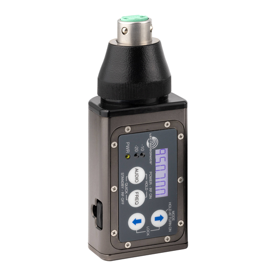
Wideband plug-on transmitter
with digital hybrid wireless technology
Hide thumbs
Also See for HMa:
- Quick start manual (13 pages) ,
- Instruction manual (24 pages) ,
- Instruction manual (24 pages)
Table of Contents
Advertisement
Quick Links
Download this manual
See also:
Instruction Manual
Advertisement
Table of Contents

Related Manuals for Lectrosonics HMa


Summary of Contents for Lectrosonics HMa
- Page 1 INSTRUCTION MANUAL Wideband Plug-On Transmitter With Digital Hybrid Wireless Technology ® Digital Hybrid Wireless ® US Patent 7,225,135 Fill in for your records: Serial Number: Rio Rancho, NM, USA Purchase Date: www.lectrosonics.com...
- Page 2 LECTROSONICS, INC.
-
Page 3: Table Of Contents
Wideband Digital Hybrid Plug-On Transmitter ® Table of Contents Thank you for selecting a Lectrosonics HMa plug-On transmitter. The unique design provides several distinct features for professional applications: General Technical Description ..........4 Wideband Design ..............4 • Outstanding RF operating range Digital Hybrid Wireless Technology ........4... -
Page 4: General Technical Description
General Technical Description Wideband Design channel as efficiently and robustly as possible, yield- The HMa transmitter uses ±75 kHz wide deviation for an excellent signal to noise ratio and wide dynamic ing audio performance that rivals that of wholly digital systems, without the power and bandwidth problems range. -
Page 5: Input Limiter
Lectrosonics 100 and 200 Series and IFB receivers. It will also work with certain non-Lectroson- ics receivers. Contact your sales representative or the factory for a complete list of compatible non-Lectroson- ics receivers. -
Page 6: Controls And Functions
At UHF frequencies the length of the housing is similar to 1/4 wavelength of the operating frequency, so the antenna is surprisingly efficient, which helps extend the operating range and suppress noise and interfer- ence. LECTROSONICS, INC. -
Page 7: Battery Installation
Wideband Digital Hybrid Plug-On Transmitter ® Battery Installation Attaching/Removing a Microphone The transmitter is powered by two AA batteries. Note: Standard zinc-carbon batteries marked The spring loaded coupler under the XLR jack main- “heavy-duty” or “long-lasting” are not adequate. tains a secure fit to the microphone jack with continu- ous pressure applied by an internal spring. -
Page 8: Operating Instructions
• 100 - For Lectrosonics 100 Series receivers. Compatibility Mode: CP 400 • 3 - (Mode 3) For non-Lectrosonics analog receiv- ers. Contact the the factory for details. RF Power Output: • IFB - For Lectrosonics IFB receivers. Operating Frequency 482.875... -
Page 9: Lcd Backlight Settings
Power Back On (DOWN Button Menu) it for the loudest voice. PBAC (Power back on after power loss) allows the unit 1) With the HMa powered off, insert the microphone to either (1) turn back on after power loss or (0) remain off. -
Page 10: Audio Screen
Repeat this process until the display indicates the PH. The HMa improves on those functions and is able to use less power from the battery by using constant current sources and current limiters. With this dynam-... - Page 11 Wideband Digital Hybrid Plug-On Transmitter ® Set Up in 100kHz Mode The operating frequency can be displayed either in MHz or as a two-digit hexadecimal Frequency displayed number. The example of the in MHz two-digit display shown here indicates CH (channel) and 2C as the frequency.
-
Page 12: Special Purpose Barrel Adapters
Earthworks M30. The adapter has common mode checks for suppressing RF noise. If your microphone signal exhibits the problems listed above when connected to a UH400, HM or HMa trans- mitter, insert the adapter between the microphone and the transmitter. -
Page 13: Accessories
MC5AX Optional adapter for connecting a lavaliere microphone to the HMa or HM transmitters. TA5M to XLR3-M connectors. Passes transmitter phantom power to bias the electret lavaliere microphone. Includes zener protection to limit bias voltage to protect the microphone if transmitter phantom power is set too high. -
Page 14: Troubleshooting
5) Receiver/Transmitter Compatibility Mode mismatched. EXCESSIVE FEEDBACK 1) Transmitter gain (audio level) too high. Check gain adjustment and/or reduce receiver output level. 2) Talent standing too close to speaker system. 3) Mic is too far from user’s mouth. LECTROSONICS, INC. - Page 15 Wideband Digital Hybrid Plug-On Transmitter ® SYMPTOM POSSIBLE CAUSE HISS AND NOISE -- AUDIBLE DROPOUTS 1) Transmitter gain (audio level) far too low. 2) Receiver antenna missing or obstructed. 3) Operating range too great. 4) Signal interference. Turn off transmitter. If receiver’s signal strength indicator does not drop to nearly zero, this indicates an interfering signal may be the problem.
-
Page 16: Specifications And Features
Input limiter: Soft limiter, 30 dB range Gain control range: 55 dB Modulation indicators: Dual bicolor LEDs indicate modulation of –20, -10, 0, +10 dB referenced to full modulation. Controls: Control panel with LCD and four membrane switches. LECTROSONICS, INC. - Page 17 FCC Notice: For body worn operation, this transmitter model has been tested and meets the FCC RF exposure guidelines when used with the Lectrosonics accessories sup- plied or designated for this product. Use of other accessories may not ensure compliance with FCC RF exposure guidelines. Contact Lectrosonics if you have any questions or need more information about RF exposure using this product.
-
Page 18: Service And Repair
LECTROSONICS’ Service Department is equipped and staffed to quickly repair your equipment. In warranty repairs are made at no charge in accordance with the terms of the warranty. Out-of-warranty repairs are charged at a modest flat rate plus parts and shipping. -
Page 20: Limited One Year Warranty
This warranty does not apply to used or demonstrator equipment. Should any defect develop, Lectrosonics, Inc. will, at our option, repair or replace any defective parts without charge for either parts or labor. If Lectrosonics, Inc. cannot correct the defect in your equipment, it will be replaced at no charge with a similar new item.
Need help?
Do you have a question about the HMa and is the answer not in the manual?
Questions and answers