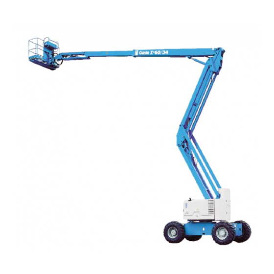
Genie Z-60/34 Operator's Manual
Articulated boom lift
Hide thumbs
Also See for Z-60/34:
- Service manual (183 pages) ,
- Operator's manual (35 pages) ,
- Operator's manual supplement (7 pages)

Related Manuals for Genie Z-60/34


Summary of Contents for Genie Z-60/34
- Page 1 Operator’s Manual Z-60 34 with Maintenance Information Seventh Edition First Printing Part No. 133083...
-
Page 2: Table Of Contents
Second Printing, August 2004 Sixth Edition: Second Printing, June 2006 Seventh Edition: First Printing, December 2007 "Genie" and "Z" are registered trademarks of Genie Industries in the U.S.A. and many other countries. Printed on recycled paper Printed in U.S.A. Z-60/34... -
Page 3: Introduction
Operator's Manual Introduction Owners, Users and Operators: Genie appreciates your choice of our machine for your application. Our number one priority is user safety, which is best achieved by our joint efforts. We feel that you make a major contribution to... - Page 4 Seventh Edition · First Printing Introduction Hazard Classification Intended Use Genie uses symbols, color coding and signal This machine is intended to be used only to lift words to identify the following: personnel, along with their tools and materials to an aerial work site.
-
Page 5: Symbol And Hazard Pictorial Definitions
Stop engine. energy starting Platform downhill: Platform uphill: aids on machines 1 Retract primary 1 Lower primary equipped with 2 Lower secondary 2 Lower secondary glow plugs. 3 Lower primary 3 Retract primary Part No. 133083 Z-60/34... - Page 6 Avoid contact. Tie-down Tie-down Weight of welder Wind speed instructions instructions reduces capacity Turntable lock can Keep away from Collision hazard Keep away from Tire pressure shear. moving parts. moving parts. Z-60/34 Part No. 133083...
-
Page 7: General Safety
Seventh Edition · First Printing Operator's Manual General Safety Safety signs and locations Part No. 133083 Z-60/34... - Page 8 Operator's Manual Seventh Edition · First Printing General Safety Safety signs and locations Z-60/34 Part No. 133083...
- Page 9 Seventh Edition · First Printing Operator's Manual General Safety Safety signs and locations Part No. 133083 Z-60/34...
-
Page 10: Personal Safety
Operators must comply with employer, job site and governmental rules regarding the use of personal protective equipment. All PFPE must comply with applicable governmental regulations, and must be inspected and used in accordance with the PFPE manufacturer’s instructions. Z-60/34 Part No. 133083... -
Page 11: Work Area Safety
If using accessories, read, understand and obey 50 to 200KV 4.6 m the decals and instructions with the accessory. 200 to 350KV 6.1 m 350 to 500KV 7.6 m 500 to 750KV 10.6 m 750 to 1000KV 13.7 m Part No. 133083 Z-60/34... - Page 12 If the tilt alarm sounds with the Do not tie the boom or platform to adjacent platform downhill: structures. 1 Retract the primary Do not place loads outside the platform perimeter. boom. 2 Lower the secondary boom. 3 Lower the primary boom. Z-60/34 Part No. 133083...
- Page 13 Do not use the platform controls to free a platform that is caught, snagged or otherwise prevented from normal motion by an adjacent structure. All personnel must be removed from the platform before attempting to free the platform using the ground controls. Part No. 133083 Z-60/34...
- Page 14 Lower the platform entry mid-rail or close the entry gate before operating. Do not enter or exit the platform unless the machine is in the stowed position and the platform is at ground level. Z-60/34 Part No. 133083...
- Page 15 All compartments must out and/or precautions have been taken to prevent remain closed and secured during operation. any potential collision. Part No. 133083 Z-60/34...
- Page 16 Avoid contact with electrical terminals. Be sure all maintenance has been performed as specified in this manual and the appropriate Genie service manual. Be sure all decals are in place and legible. Be sure the operator’s, safety and responsibilities manuals are complete, legible and in the storage container located on the platform.
- Page 17 Maximum panel area: 3 m Do not cause a horizontal force or side load to the machine by raising or lowering a fixed or overhanging load. Electrocution Hazard: Keep pipes away from all energized electrical conductors. Part No. 133083 Z-60/34...
- Page 18 3 Rotate the turntable so that the boom is between the non-steer wheels. 4 Turn the key switch to the off position and remove the key to secure from unauthorized use. 5 Chock the wheels. Z-60/34 Part No. 133083...
-
Page 19: Legend
2 Manual storage container 3 Sliding mid rail 4 Lanyard anchorage point 5 Non- steer tire 6 Steer tire 7 Ground controls 8 Primary boom 9 Jib boom 10 Platform controls 11 Platform 12 Secondary boom Part No. 133083 Z-60/34... -
Page 20: Controls
3 Platform rotate switch - Rabbit symbol: high idle 4 Jib boom up/down switch 10 Gasoline/LPG models: Gasoline/LPG select switch 5 Auxiliary power switch 11 Red Emergency Stop button 6 Drive speed select switch 7 Glow plug switch (option) Z-60/34 Part No. 133083... - Page 21 13 Platform overload indicator light 20 Dual axis proportional control handle for 14 Machine not level indicator light (if equipped) primary boom up/down and turntable rotate left/ 15 Drive enable indicator light right functions 16 Drive enable switch Part No. 133083 Z-60/34...
- Page 22 Pull out the red Emergency Stop button to 5 Auxiliary power switch the on position to operate the machine. Use auxiliary power if the primary power source (engine) fails. Simultaneously hold the auxiliary power switch to either side and activate the desired function. Z-60/34 Part No. 133083...
- Page 23 Move the Light on indicates that the boom has moved just control handle to the left and the past either non-steer wheel and drive function turntable will rotate to the left. has been interrupted. Part No. 133083 Z-60/34...
- Page 24 20A breaker for oil cooler and options Key switch for platform/off/ground selection 15A breaker for control electrical circuits Oil pressure gauge (option) Jib boom up/down switch Voltage gauge (option) Platform level switch Red Emergency Stop button Platform rotate switch Z-60/34 Part No. 133083...
- Page 25 6 Auxiliary power switch secondary boom will lower. Use auxiliary power if the primary power source (engine) fails. Simultaneously hold the auxiliary power switch to either side and activate the desired function. Part No. 133083 Z-60/34...
- Page 26 20 15A breaker for control electrical circuits 21 Jib boom up/down switch Move the jib boom switch up and the jib boom will raise. Move the jib boom switch down and the jib boom will lower. Z-60/34 Part No. 133083...
-
Page 27: Inspections
Scheduled maintenance inspections shall be performed by qualified service technicians, according to the manufacturer's specifications and the requirements listed in the responsibilities manual. Part No. 133083 Z-60/34... - Page 28 Electrical components, wiring and electrical cables Hydraulic hoses, fittings, cylinders and manifolds Fuel and hydraulic tanks Drive and turntable motors and drive hubs Boom wear pads Tires and wheels Z-60/34 Part No. 133083...
- Page 29 3 Always perform function tests prior to use. Know and understand the function tests before going on to the next section. 4 Inspect the workplace. 5 Only use the machine as it was intended. Part No. 133083 Z-60/34...
- Page 30 8 Hold the function enable switch to either side and activate each boom and platform function toggle switch. Result: All boom and platform functions should operate through a full cycle. The descent alarm should sound while the boom is lowering. Z-60/34 Part No. 133083...
- Page 31 24 Press down the foot switch and attempt to start drive chassis. the engine by moving the start toggle switch to either side. Result: The engine should not start. Part No. 133083 Z-60/34...
- Page 32 Result: The maximum achievable drive speed range shown. with the primary boom extended should not exceed 30 cm per second. 37 Move the drive control handle off center. Result: The drive function should not operate. Z-60/34 Part No. 133083...
- Page 33 Result: The three remaining tires should stay in firm contact with the ground. 52 Drive both steer tires up onto a 15 cm block or curb. Result: The non-steer tires should stay in firm contact with the ground. Part No. 133083 Z-60/34...
- Page 34 Result: All boom and steer functions should not operate. 62 Move the function override switch to either side. 63 Activate each function control handle or toggle switch. Result: All boom and steer functions should operate. Z-60/34 Part No. 133083...
- Page 35 It should be performed by the operator prior to moving the machine to the workplace. It is the operator's responsibility to read and remember the workplace hazards, then watch for and avoid them while moving, setting up and operating the machine. Part No. 133083 Z-60/34...
- Page 36 97815 Label - Lower Mid-rail 44981 Label - Air Line to Platform (option) 114166 Label - Transport Diagram 52965 Cosmetic - Genie Z-60/34 114244 Label - Wheel Load 52966 Cosmetic - 4 x 2 114247 Label - Fall Hazard 52967...
- Page 37 Seventh Edition · First Printing Operator's Manual Inspections Ground Controls Side Platform Drive Chassis Shading indicates decal is hidden from view, i.e. under covers Engine Side Part No. 133083 Z-60/34...
-
Page 38: Operating Instructions
That means 4 Inspect the workplace. every new operator should perform a pre-operation inspection, function tests, and a workplace 5 Only use the machine as it was intended. inspection before using the machine. Z-60/34 Part No. 133083... - Page 39 5 minutes before operating to prevent hydraulic system damage. 4 Simultaneously hold auxiliary power switch on and activate the desired function. The drive and steer functions will not operate with auxiliary power. Part No. 133083 Z-60/34...
- Page 40 4 Start the engine. Do not press down the foot platform controls and the drive chassis to identify switch when starting the engine. the direction the machine will travel. Machine travel speed is restricted when the booms are raised. Z-60/34 Part No. 133083...
- Page 41 See You will need: Transport and Lifting section. carpenter’s level straight piece of wood, at least 1 m long tape measure Part No. 133083 Z-60/34...
- Page 42 · Turtle symbol: Foot level. The tilt alarm will be sounding switch activated low when this light is on. Move the idle machine to a firm level surface. · Rabbit symbol: Foot switch activated high idle Z-60/34 Part No. 133083...
- Page 43 3 Rotate the turntable so that the boom is between the non-steer wheels. 4 Turn the key switch to the off position and remove the key to secure from unauthorized use. 5 Chock the wheels. Part No. 133083 Z-60/34...
- Page 44 3 Secure each U-bolt with 2 washers and 2 nuts. a strap e pipe cradle weldment b U-bolts middle platform c pipe cradle mount railing d upper platform g flat washers railing -inch nylock nuts Z-60/34 Part No. 133083...
- Page 45 Tip-over hazard. The weight of the pipe cradle assembly and the load in the pipe cradles may limit the maximum number of occupants in the platform. Maximum Pipe Cradle Capacity All models 90.7 kg Pipe Cradle Assembly Weight 9.5 kg Part No. 133083 Z-60/34...
- Page 46 8 Place the tube between the panel cradle and the platform floor. Insert the U-bolt through the floor, around the tube and into the panel cradle base. 9 Repeat above for the second set of parts. Z-60/34 Part No. 133083...
- Page 47 U-bolt mounting 3 Center the load on the platform. rubber slots bumper 1 4 Secure the load to the platform using the strap. Tighten the strap. panel decal cradle base hook piece padding clamp hook Part No. 133083 Z-60/34...
-
Page 48: Transport And Lifting Instructions
Transportation regulations, other localized regulations, and their company policy. Genie customers needing to containerize any Free-wheel Configuration for lift or Genie product should source a qualified Winching freight forwarder with expertise in preparing, loading and securing construction and lifting Chock the wheels to prevent the machine from equipment for international shipment. - Page 49 Inspect the entire machine for loose or unsecured items. Securing the Chassis Use chains of ample load capacity. Use a minimum of 5 chains. Adjust the rigging to prevent damage to the chains. Truck bed Part No. 133083 Z-60/34...
- Page 50 See the serial label for the machine weight. Adjust the rigging to prevent damage to the machine and to keep the machine level. Chassis Lifting Points (2) 1.27 m Chassis Lifting Points (2) 1.02 m Z-60/34 Part No. 133083...
-
Page 51: Maintenance
Oil type 15W-40 and the requirements specified in the responsibilities manual. Oil type - cold conditions 5W-40 Use only Genie approved replacement parts. Ford DSG-423 EFI Engine (EPA Compliant) Oil type 5W-20 Deutz F3L 2011F Engine (Tier II) Maintenance Symbols Legend... - Page 52 The fluid level should be at the 2 Add oil as needed. mark. FULL Hydraulic oil specifications 2 Add fluid as needed. Hydraulic oil type Chevron Rykon Note: Do not remove the radiator cap. Premium MV equivalent Z-60/34 Part No. 133083...
- Page 53 3 Be sure that the battery hold-down bracket is Tire pressure 4.5 bar secure. High flotation tire pressure 4.5 bar Note: Adding terminal protectors and a corrosion preventative sealant will help eliminate corrosion on the battery terminals and cables. Part No. 133083 Z-60/34...
- Page 54 Machines that have been out of service for more than three months must receive the quarterly inspection before they are put back into service. Z-60/34 Part No. 133083...
-
Page 55: Specifications
Platform leveling self-leveling Platform rotation 180° AC outlet in platform standard Vibration value does not exceed 2.5 m/s Continuous improvement of our products is a Genie policy. Product specifications are subject to change without notice or obligation. Part No. 133083 Z-60/34... - Page 56 Operator's Manual Seventh Edition · First Printing Specifications Z-60/34 Range of Motion 21.4 m 18.3 m 15.3 m 12.2 m 9.2 m 6.1 m 3.1 m 0 m 3.1 m 6.1 m 9.2 m 12.2 m Z-60/34 Part No. 133083...
Need help?
Do you have a question about the Z-60/34 and is the answer not in the manual?
Questions and answers