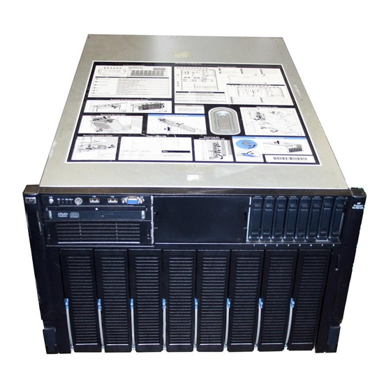
HP ProLiant DL785 User Manual
Generation 5 server
Hide thumbs
Also See for ProLiant DL785:
- Quickspecs (42 pages) ,
- Option installation manual (7 pages) ,
- Limited warranty (15 pages)

Related Manuals for HP ProLiant DL785


Summary of Contents for HP ProLiant DL785
-
Page 1: User Guide
HP ProLiant DL785 Generation 5 Server User Guide User Guide HP Part Number: AH233-9003A_ed2 Published: January 2009 Edition: 2... - Page 2 © Copyright 2008–2009 Hewlett-Packard Development Company, L.P. The information contained herein is subject to change without notice. The only warranties for HP products and services are set forth in the express warranty statements accompanying such products and services. Nothing herein should be construed as constituting an additional warranty. HP shall not be liable for technical or editorial errors or omissions contained herein.
-
Page 3: Table Of Contents
Table of Contents 1 Component identification....................7 Front panel components.........................7 Front panel LEDs and buttons........................9 System Insight Display LEDs.......................10 SAS and SATA hard drive LEDs......................12 SAS and SATA hard drive LED combinations..................12 Processor memory cell components.....................13 Rear panel components.........................14 Rear panel LEDs and buttons.......................15 Power supply LED..........................16 Internal components..........................16 SPI board components..........................18... - Page 4 HP ROM-Based Setup Utility......................62 Using RBSU..........................62 Auto-configuration process......................62 Boot options..........................63 BIOS Serial Console........................63 HP ProLiant Essentials Rapid Deployment Pack.................63 Option ROM Configuration for Arrays....................64 Array Configuration Utility........................64 Re-entering the server serial number and product ID................64 Management tools..........................65 Automatic Server Recovery......................65 Integrated Lights-Out 2 technology....................65...
- Page 5 Operating system version support....................69 Change control and proactive notification..................69 Care Pack............................69 7 Troubleshooting......................71 Troubleshooting resources........................71 Pre-diagnostic steps..........................71 Important safety information......................71 Symbols on equipment.......................72 Warnings and cautions.......................72 Symptom information........................73 Prepare the server for diagnosis......................74 Loose connections..........................74 Service notifications..........................75 Server power-on problems flowchart....................75 Troubleshooting flowcharts........................76 Start diagnosis flowchart.........................77 General diagnosis flowchart......................77...
- Page 6 1 1 Technical support......................97 Before you contact HP...........................97 HP contact information.........................97 Customer Self Repair..........................97 Réparation par le client (CSR)......................98 Riparazione da parte del cliente......................99 Customer Self Repair........................99 Reparaciones del propio cliente.....................100 Customer Self Repair........................100 Reparo feito pelo cliente........................101 A Acronyms and abbreviations..................105 Index..........................107...
-
Page 7: Component Identification
1 Component identification In this section • “Front panel components” (page 7) • “Front panel LEDs and buttons” (page 9) • “System Insight Display LEDs” (page 10) • “SAS and SATA hard drive LEDs” (page 12) • “SAS and SATA hard drive LED combinations” (page 12) •... - Page 8 Item Description Hard drive bay 4 right Hard drive bay 5 right Hard drive bay 6 right Hard drive bay 7 right Hard drive bay 8 right not shown Hard drive bay 1 left (optional) not shown Hard drive bay 2 left (optional) not shown Hard drive bay 3 left (optional) not shown...
-
Page 9: Front Panel Leds And Buttons
Front panel LEDs and buttons Item Description Color Status UID button and LED UID button is not activated Solid blue UID button is activated for server identification Flashing blue Server is being remotely managed External health LED Normal (system is off or in standby mode) Solid green Normal (system is powered on) -
Page 10: System Insight Display Leds
System has ac power and is powered System Insight Display LEDs The front panel health LEDs indicate only the current hardware status. In some situations, HP SIM might report server status differently than the health LEDs because the software tracks more... - Page 11 system attributes. The System Insight Display LEDs identify components experiencing an error, event, or failure. CAUTION: Do not block airflow by pushing the SID flush against the server while it is in the down position. IMPORTANT: When removing the access panel to view the Systems Insight Display LEDs, leave the server powered on.
-
Page 12: Sas And Sata Hard Drive Leds
Component PROCESSOR/MEMORY BOARD X Processor PROC X PROCESSOR/MEMORY BOARD X Processor DIMM board BOARD X SAS and SATA hard drive LEDs Item Description Color Status Fault/UID LED Amber Drive failure Flashing amber Fault-process activity Blue Unit identification is active No fault-process activity Online/activity LED Green Drive activity... -
Page 13: Processor Memory Cell Components
Online/activity LED Fault/UID LED (green) (amber/blue) Interpretation The drive is online, but is not currently active. Flashing (1 Hz) Flashing amber CAUTION: Do not remove the drive. Removing a drive can terminate the (1Hz) current operation and cause data loss. The drive is part of an array that is undergoing capacity expansion or stripe migration, but a predictive failure alert has been received for this drive. -
Page 14: Rear Panel Components
Item Description DIMM slot 6C DIMM slot 7D DIMM slot 8D Processor socket Rear panel components Item Description NIC connector 1 Keyboard connector USB connector Video connector Serial connector iLO 2 connector Mouse connector NIC connector 2 Power supply 1 Power supply 2 Power supply 3 Redundant power supply 4 (optional) -
Page 15: Rear Panel Leds And Buttons
Item Description Fan 5 Fan 6 Rear panel LEDs and buttons Item Description LED Color Status Solid blue Activated Flashing blue Server remotely managed Deactivated LAN Link LED Green Linked to network Not linked to network LAN Activity LED Green (solid or flashing) Network activity No network activity Rear panel LEDs and buttons... -
Page 16: Power Supply Led
Power supply LED Color Status No ac power Blinking green ac power; standby power on Solid green Full power on; normal operation Blinking amber Power supply failure Internal components Item Description Media module Fan 3 Fan 2 Component identification... - Page 17 Item Description Fan 1 System maintenance switch SPI Board PCI Express x8 non-hot-plug expansion slot 11 PCI Express x16 non-hot-plug expansion slot 10 PCI Express x8 non-hot-plug expansion slot 9 PCI Express x16 non-hot-plug expansion slot 8 PCI Express x4 non-hot-plug expansion slot 7 PCI Express x4 non-hot-plug expansion slot 6 PCI Express x16 non-hot-plug expansion slot 5 PCI Express x4 non-hot-plug expansion slot 4...
-
Page 18: Spi Board Components
Combo PCIe/HTx I/O backplane Item Description HyperTransport non-hot-plug expansion slot 8 PCI Express x4 non-hot-plug expansion slot 7 PCI Express x4 non-hot-plug expansion slot 6 PCI Express x16 non-hot-plug expansion slot 5 PCI Express x4 non-hot-plug expansion slot 4 PCI Express x4 non-hot-plug expansion slot 3 PCI Express x4 non-hot-plug expansion slot 2 PCI Express x8 non-hot-plug expansion slot 1 SPI board components... -
Page 19: Battery Pack Leds
Position Description Switch Function Configuration lock System configuration can be changed System configuration is locked Reserved — Reserved Reserved — Reserved Password protection override Password is enabled Password is disabled Reset configuration Switch has no function ROM reads system configuration as invalid POST LED switch 1 Table 1-1 (page 19) for details. - Page 20 A fullycharged battery can normally preserve data for at least two days. The battery lifetime also depends on the cache module size. For further information, refer to the controller QuickSpecs on the HP website (http://www.hp.com). Double flash, then The cache microcontroller is waiting for the host controller to communicate.
-
Page 21: Fan Locations
Fan locations Item Description Fan 1 Fan 2 Fan 3 Fan 4 Fan 5 Fan 6 Fan locations... -
Page 23: Setup
For more information on Care Packs, refer to the HP website (http://www.hp.com/hps/carepack/servers/cp_proliant.html). Rack planning resources The rack resource kit ships with all HP branded or Compaq branded 9000, 10000, and H9 series racks. For more information on the content of each resource, refer to the rack resource kit documentation. -
Page 24: Optimum Environment
Leave a minimum clearance of 121.9 cm (48 in) from the back of the rack to the back of another rack or row of racks. HP servers draw in cool air through the front door and expel warm air through the rear door. Therefore, the front and rear rack doors must be adequately ventilated to allow ambient room air to enter the cabinet, and the rear door must be adequately ventilated to allow the warm air to escape from the cabinet. -
Page 25: Power Requirements
The maximum recommended ambient operating temperature (TMRA) for most server products is 35°C (95°F). CAUTION: Follow these guidelines to reduce the risk of damage to the equipment when installing third-party options: • Do not permit optional equipment to impede airflow around the server or to increase the internal rack temperature beyond the maximum allowable limits. -
Page 26: Rack Warning And Cautions
For electrical power ratings on options, refer to the product rating label or the user documentation supplied with that option. WARNING! To reduce the risk of personal injury, fire, or damage to the equipment, do not overload the ac supply branch circuit that provides power to the rack. Consult the electrical authority with jurisdiction over wiring and installation requirements of your facility. -
Page 27: Electrical Grounding Requirements
WARNING! To reduce the risk of personal injury or damage to the equipment, be sure of the following: • The leveling jacks are extended to the floor. • The full weight of the rack rests on the leveling jacks. • The stabilizing feet are attached to the rack if it is a single-rack installation. -
Page 28: Identifying Rack Server Shipping Carton Contents
Because of the high ground leakage currents associated with multiple servers connected to the same power source, HP recommends the use of a PDU that is either permanently wired to the building’s branch circuit or includes a nondetachable cord that is wired to an industrial-style plug. -
Page 29: Installing The Operating System
For information on using these installation paths, refer to the SmartStart installation poster in the HP ProLiant Essentials Foundation Pack included with the server. Registering the server To register the server, refer to the HP Registration website (http://register.hp.com). Installing the operating system... -
Page 31: Operations
3 Operations In this section • “Power up the server” (page 31) • “Power down the server” (page 31) • “Extending the server from the rack” (page 31) • “Removing the access panel” (page 32) • “Accessing the System Insight Display” (page 33) •... -
Page 32: Removing The Access Panel
NOTE: The release latches lock into place when the rails are fully extended. WARNING! To reduce the risk of personal injury or equipment damage, be sure that the rack is adequately stabilized before extending a component from the rack. WARNING! To reduce the risk of personal injury, be careful when pressing the server rail release latches and sliding the server into the rack. -
Page 33: Accessing The System Insight Display
NOTE: The T-15 Torx screwdriver is shipped with the server and can be located on the rear panel (“Rear panel components” (page 14)). Lift up on the hood latch and remove the access panel. After installing hardware options, replace the access panel. Be sure that the panel is securely locked into place before powering up the server. -
Page 34: Hot-Plug Fans
Flip down the SID for easier viewing. CAUTION: Do not block airflow by pushing the SID flush against the server while it is in the down position. Hot-plug fans The server supports redundant hot-plug fans, each with two individual fans rotors, in a 5+1 configuration to provide proper airflow to the server. -
Page 35: Replacing Internally Accessed Hot-Plug Fans
Pull the fan straight up and out of the chassis. IMPORTANT: Remove and replace one fan at a time. If the system detects two fan failures, the server shuts down to avoid thermal damage. Install a new hot-plug fan. CAUTION: To prevent server components from overheating, replace the fan within 20 seconds. - Page 36 Pull the fan straight up and out of the chassis. IMPORTANT: Remove and replace one fan at a time. If the system detects two fan failures, the server shuts down to avoid thermal damage. Install a new hot-plug fan. CAUTION: To prevent server components from overheating, replace a fan within 20 seconds.
-
Page 37: Removing The System Battery
Remove the battery. To replace the component, reverse the removal procedure. Run the RBSU to configure the server after replacing the battery. For more detailed information see the HP ROM-Based Setup Utility User Guide on the Documentation CD. Removing the system battery... -
Page 39: Hardware Options Installations
4 Hardware options installations In this section • “Introduction” (page 39) • “Processor options” (page 39) • “Memory options” (page 46) • “Hard drive guidelines” (page 47) • “Installing DVD or CD drive” (page 48) • “Hot-plug power supplies” (page 49) •... - Page 40 CAUTION: When working with the processor memory cell always place the component on a flat, level, antistatic surface. Press the two airflow baffle release tabs, pivot the airflow baffle up, and remove the airflow baffle. Hardware options installations...
-
Page 41: Installing A Processor
Installing a processor To install a processor: WARNING! To reduce the risk of personal injury from hot surfaces, allow the heatsink to cool before touching it. Open the heatsink retaining bracket. Remove the heatsink. Open the processor retaining latch and the processor socket retaining bracket. Processor options... - Page 42 Align the processor installation tool with the socket and install the processor. Hardware options installations...
- Page 43 CAUTION: The processor is designed to fit only one way into the socket. Use the alignment guides on the processor and socket to properly align the processor with the socket. Press down firmly until the processor installation tool clicks and separates from the processor, then remove the processor installation tool.
- Page 44 Close the processor retaining latch and the processor socket retaining bracket. Hardware options installations...
- Page 45 Clean the old thermal grease from the heatsink with the alcohol swab. Allow the alcohol to evaporate before continuing. Apply all the grease to the top of the processor in one of the following patterns to ensure even distribution. Install the heatsink. 10.
-
Page 46: Memory Options
12. Install the processor memory cell into the server. 13. Power up the server. Memory options Each processor memory cell can hold two to eight DIMMs. At least one pair of DIMMs must be installed in slots 1A and 2A on each processor memory cell to operate the server. The following DDR2 667-MHz DIMM sizes are supported: •... -
Page 47: Hard Drive Guidelines
Install the DIMM. Hard drive guidelines When adding hard drives to the server, observe the following guidelines: • The system automatically sets all device numbers. • If only one hard drive is used, install it in the bay with the lowest device number. •... -
Page 48: Installing Dvd Or Cd Drive
Install the hard drive into the server. Be sure that the hard drive seats firmly into the connector in the back of the drive cage. Close the ejector lever. Determine the status of the hard drive from the hot-plug hard drive LEDs, see “SAS and SATA hard drive LEDs”... -
Page 49: Hot-Plug Power Supplies
Remove the media module. Disconnect all cabling from the media module. Press the media module release latch. Pull the media module away from the server. Lift the DVD release tab on the left side of the media module and push the drive out from the rear. - Page 50 Install the power supply. Connect the power cord to the power supply. Secure the power cords to the retaining clip. Connect the power cord to the power source. Be sure that the power supply LED is green. Hardware options installations...
-
Page 51: Expansion Boards
Be sure that the front panel external health LED is green. IMPORTANT: For maximum server availability, be sure that the primary and redundant power supplies are powered by separate ac power sources. NOTE: If the server will be shipped to another location after configuration, install a shipping screw into each power supply. -
Page 52: Installing An Expansion Board
Combo PCIe/HTx I/O backplane Item Description Blank slot HyperTransport non-hot-plug expansion slot 9 Blank slot HyperTransport non-hot-plug expansion slot 8 PCI Express x4 non-hot-plug expansion slot 7 PCI Express x4 non-hot-plug expansion slot 6 PCI Express x16 non-hot-plug expansion slot 5 PCI Express x4 non-hot-plug expansion slot 4 PCI Express x4 non-hot-plug expansion slot 3 PCI Express x4 non-hot-plug expansion slot 2... -
Page 53: Battery-Backed Write Cache
10. Slide the server into the rack. 11. Power up the server (“Power up the server” (page 31)). Battery-backed write cache The HP BBWC protects against hard boot, power, controller, and midplane board failures. The server supports the following battery-backed options: • 256-MB BBWC •... - Page 54 Along with the cache module, the battery pack provides transportable data protection, increases overall controller performance, and maintains any cached data for up to 72 hours after the server loses power. The NiMH batteries in the battery pack are continuously recharged by a trickle-charging process whenever the system power is on.
- Page 55 Install the new cache on the controller. Press firmly above each connector to ensure good electrical contact. IMPORTANT: If the cache is not properly connected, the controller can not boot. Replace the controller in the server. The controller is installed in expansion slot 11 Battery-backed write cache...
- Page 56 Install the battery, if applicable. Install the battery pack into the server. Plug the battery cable (supplied in the battery pack kit) into the battery pack. Route the cable and connect it to the cache module. NOTE: After installing a battery pack, you might see a POST message during reboot indicating that the array accelerator (cache) is temporarily disabled.
-
Page 57: Cabling
This section provides guidelines that help you make informed decisions about cabling the server and hardware options to optimize performance. For information on cabling peripheral components, refer to the white paper on high-density deployment at the HP website (http://www.hp.com/products/servers/platforms). BBWC cabling Cabling overview... -
Page 58: Sas And Sata Hard Drive Cabling
SAS and SATA hard drive cabling Cabling... -
Page 59: High Power Graphics Card Cabling
CAUTION: When routing cables, always be sure that the cables are not in a position where they can be pinched or crimped. High power graphics card cabling IMPORTANT: Install high powered graphics cards in PCIe 16x slots for optimum performance. The server can power a maximum of four auxiliary high powered graphics card power connections. -
Page 61: Software And Configuration Utilities
(“Array Diagnostic Utility” (page 68)), and Erase Utility SmartStart is included in the HP ProLiant Essentials Foundation Pack. For more information about SmartStart software, refer to the HP ProLiant Essentials Foundation Pack or the HP website (http://h18013.www1.hp.com/products/servers/management/smartstart/ index.html). SmartStart Scripting Toolkit The SmartStart Scripting Toolkit is a server deployment product that delivers an unattended automated installation for high-volume server deployments. -
Page 62: Hp Rom-Based Setup Utility
Selecting the primary boot controller • Configuring memory options • Language selection For more information on RBSU, refer to the HP ROM-Based Setup Utility User Guide on the Documentation CD or the HP website (http://www.hp.com/support/smartstart/ documentation). Using RBSU To use RBSU, use the following keys: •... -
Page 63: Boot Options
RBSU by pressing the F9 key when prompted. After the settings are selected, exit RBSU and allow the server to reboot automatically. For more information, refer to the HP ROM-Based Setup Utility User Guide on the Documentation CD or the HP website (http://www.hp.com/support/smartstart/documentation). -
Page 64: Option Rom Configuration For Arrays
1) or later. For Linux servers, refer to the README.TXT file for additional browser and support information. For more information, refer to the HP Array Configuration Utility User Guide on the Documentation CD or the HP website (http://www.hp.com). Re-entering the server serial number and product ID After you replace the SPI board, you must re-enter the server serial number and the product ID. -
Page 65: Management Tools
ASR increases server availability by restarting the server within a specified time after a system hang or shutdown. At the same time, the HP SIM console notifies you by sending a message to a designated pager number that ASR has restarted the system. You can disable ASR from the HP SIM console or through RBSU. -
Page 66: Hp Systems Insight Manager
HP Systems Insight Manager HP SIM is a web-based application that allows system administrators to accomplish normal administrative tasks from any remote location, using a web browser. HP SIM provides device management capabilities that consolidate and integrate management data from HP and third-party devices. -
Page 67: Usb Support
USB device drivers. HP provides support for USB devices before the operating system loads through legacy USB support, which is enabled by default in the system ROM. HP hardware supports USB version 1.1 or 2.0, depending on the version of the hardware. -
Page 68: Array Diagnostic Utility
Pack. Array Diagnostic Utility The HP Array Diagnostics Utility is a web-based application that creates a report of all HP storage controllers and disk drives. This report provides vital information to assist in identifying faults or conditions that may require attention. ADU can be accessed from the SmartStart CD (“SmartStart software”... -
Page 69: Proliant Support Packs
Refer to the operating system support matrix (http://www.hp.com/go/supportos). Change control and proactive notification HP offers Change Control and Proactive Notification to notify customers 30 to 60 days in advance of upcoming hardware and software changes on HP commercial products. For more information, refer to the HP website (http://www.hp.com/go/pcn). -
Page 71: Troubleshooting
To obtain the guide, refer to any of the following sources and then select the HP ProLiant Servers Troubleshooting Guide: •... -
Page 72: Symbols On Equipment
Symbols on equipment The following symbols may be placed on equipment to indicate the presence of potentially hazardous conditions. This symbol indicates the presence of hazardous energy circuits or electric shock hazards. Refer all servicing to qualified personnel. WARNING! To reduce the risk of injury from electric shock hazards, do not open this enclosure. -
Page 73: Symptom Information
WARNING! Only authorized technicians trained by HP should attempt to repair this equipment. All troubleshooting and repair procedures are detailed to allow only subassembly/module-level repair. Because of the complexity of the individual boards and subassemblies, no one should attempt to make repairs at the component level or to make modifications to any printed wiring board. -
Page 74: Prepare The Server For Diagnosis
HP drivers, Management Agents, and utilities, and whether they are up to date. • HP recommends you have access to the SmartStart CD for value-added software and drivers required during the troubleshooting process. • HP recommends you have access to the server documentation for server-specific information. -
Page 75: Service Notifications
Server maintenance and service guide, located on the Documentation CD, or the HP website (http:// www.hp.com/products/servers/platforms) "System open circuits and short circuits" in the HP ProLiant Servers Troubleshooting Guide located on the Documentation CD or on the HP website (http://www.hp.com/support) Service notifications... -
Page 76: Troubleshooting Flowcharts
Troubleshooting flowcharts To effectively troubleshoot a problem, HP recommends that you start with the first flowchart in this section, “Start diagnosis flowchart” (page 77)and follow the appropriate diagnostic path. If the other flowcharts do not provide a troubleshooting solution, follow the diagnostic steps in “General diagnosis flowchart”... -
Page 77: Start Diagnosis Flowchart
Start diagnosis flowchart Item Refer to “General diagnosis flowchart” (page 77) “Server power-on problems flowchart” (page 79) “POST problems flowchart” (page 81) “OS boot problems flowchart” (page 82) “Server fault indications flowchart” (page 84) General diagnosis flowchart The General diagnosis flowchart provides a generic approach to troubleshooting. If you are unsure of the problem, or if the other flowcharts do not fix the problem, use the following flowchart. - Page 78 HP ROM-BIOS/Firmware Updates website (http://h18023.www1.hp.com/support/files/ server/us/romflash.html) "General memory problems are occurring" in the HP ProLiant Servers Troubleshooting Guide located on the Documentation CD or on the HP website (http://www.hp.com/support) Server maintenance and service guide, located on the Documentation CD or the HP website (http:// www.hp.com/products/servers/platforms)
-
Page 79: Server Power-On Problems Flowchart
Server power-on problems flowchart Symptoms • • The server does not power on. • The system power LED (“System Insight Display LEDs” (page 10)) is off or amber. • The external health LED (“System Insight Display LEDs” (page 10)) is red or amber. •... - Page 80 Server maintenance and service guide, located on the Documentation CD, or the HP website (http:// www.hp.com/products/servers/platforms) "System open circuits and short circuits" in the HP ProLiant Servers Troubleshooting Guide located on the Documentation CD or on the HP website (http://www.hp.com/support) Troubleshooting...
-
Page 81: Post Problems Flowchart
Item Refer to “POST error messages and beep codes” (page 86) "Video problems" in the HP ProLiant Servers Troubleshooting Guide located on the Documentation CD or on the HP website (http://www.hp.com/support) KVM or iLO 2 documentation “Loose connections” (page 74) “Symptom information”... -
Page 82: Os Boot Problems Flowchart
Server maintenance and service guide, located on the Documentation CD or the HP website (http:// www.hp.com/products/servers/platforms) "Port 85 and iLO messages" in the HP ProLiant Servers Troubleshooting Guide located on the Documentation CD or on the HP website (http://www.hp.com/support) "General memory problems are occurring" in the HP ProLiant Servers Troubleshooting Guide located on the Documentation CD or on the HP website (http://www.hp.com/support) - Page 83 67)or in the HP ProLiant Servers Troubleshooting Guide located on the Documentation CD or on the HP website (http://www.hp.com/support) • "CD-ROM and DVD drive problems" in the HP ProLiant Servers Troubleshooting Guide located on the Documentation CD or on the HP website (http://www.hp.com/support) •...
-
Page 84: Server Fault Indications Flowchart
Server fault indications flowchart Symptoms: • Server boots, but a fault event is reported by Insight “Management Agents” (page 65) • Server boots, but the internal health LED, external health LED, or component health LED is red or amber NOTE: For the location of server LEDs and information on their statuses, refer to the server documentation. - Page 85 System Management Homepage (https://localhost:2381) “Server power-on problems flowchart” (page 79) • "Smart Array SCSI Diagnosis feature" in the HP ProLiant Servers Troubleshooting Guide located on the Documentation CD or on the HP website (http://www.hp.com/support) • Server maintenance and service guide, located on the Documentation CD or the HP website (http:// www.hp.com/products/servers/platforms)
-
Page 86: Post Error Messages And Beep Codes
POST error messages and beep codes For a complete listing of error messages, refer to the "POST error messages" in the HP ProLiant Servers Troubleshooting Guide located on the Documentation CD or on the HP website (http:// www.hp.com/support). WARNING! To avoid potential problems, ALWAYS read the warnings and cautionary information in the server documentation before removing, replacing, reseating, or modifying system components. -
Page 87: Regulatory Compliance Notices
8 Regulatory compliance notices In this section • “Regulatory compliance identification numbers” (page 87) • “Federal Communications Commission notice” (page 87) • “Declaration of conformity for products marked with the FCC logo, United States only” (page 88) • “Modifications” (page 88) •... -
Page 88: Class B Equipment
Hewlett-Packard Company P. O. Box 692000, Mail Stop 530113 Houston, Texas 77269-2000 • 1-800-HP-INVENT (1-800-474-6836). (For continuous quality improvement, calls may be recorded or monitored.) For questions regarding this FCC declaration, contact us by mail or telephone: • Hewlett-Packard Company P. -
Page 89: Canadian Notice (Avis Canadien)
Canadian notice (Avis Canadien) Class A equipment This Class A digital apparatus meets all requirements of the Canadian Interference-Causing Equipment Regulations. Cet appareil numérique de la classe A respecte toutes les exigences du Règlement sur le matériel brouilleur du Canada. Class B equipment This Class B digital apparatus meets all requirements of the Canadian Interference-Causing Equipment Regulations. -
Page 90: Japanese Notice
Japanese notice BSMI notice Korean notice Class A equipment Class B equipment Regulatory compliance notices... -
Page 91: Laser Compliance
To forward them to recycling or proper disposal, please use the public collection system or return them to HP, an authorized HP Partner, or their agents. For more information about battery replacement or proper disposal, contact an authorized reseller or an authorized service provider. -
Page 92: Power Cord Statement For Japan
Power cord statement for Japan Regulatory compliance notices... -
Page 93: Electrostatic Discharge
9 Electrostatic discharge In this section • “Preventing electrostatic discharge” (page 93) • “Grounding methods to prevent electrostatic discharge” (page 93) Preventing electrostatic discharge To prevent damaging the system, be aware of the precautions you need to follow when setting up the system or handling parts. -
Page 95: 10 Specifications
10 Specifications In this section • “Environmental specification” (page 95) • “Server specifications” (page 95) Environmental specification Specification Value Temperature range Operating 10°C to 35°C (50°F to 95°F) Non-operating -30°C to 60°C (-22°F to 140°F) Maximum wet bulb temperature 28°C (82.4°F) Relative humidity (noncondensing) Operating 10% to 90% relative humidity (Rh), 28°C (82.4°F) - Page 96 To ensure the ProLiant DL785 G5 Server has sufficient power during normal operation, a server configured with HP supported high powered graphics cards rated at 225 W or more require high line (200 - 240 V) ac server configuration. As a precaution, if these cards are installed on a low line (100 - 127 V) ac configured server the server will halt at Power-On Self-Test with a "Power Supply Solution not Sufficient"...
-
Page 97: 1 Technical Support
HP (or HP service providers or service partners) identifies that the repair can be accomplished by the use of a CSR part, HP will ship that part directly to you for replacement. There are two categories of CSR parts: Mandatory •... -
Page 98: Réparation Par Le Client (Csr)
CSR part whether a defective part must be returned to HP. In cases where it is required to return the defective part to HP, you must ship the defective part back to HP within a defined period of time, normally five (5) business days. The defective part must be returned with the associated documentation in the provided shipping material. -
Page 99: Riparazione Da Parte Del Cliente
La mancata restituzione del componente può comportare la fatturazione del ricambio da parte di HP. Nel caso di riparazione da parte del cliente, HP sostiene tutte le spese di spedizione e resa e sceglie il corriere/vettore da utilizzare. -
Page 100: Reparaciones Del Propio Cliente
HP podrá cobrarle por el de sustitución. En el caso de todas sustituciones que lleve a cabo el cliente, HP se hará cargo de todos los gastos de envío y devolución de componentes y escogerá la empresa de transporte que se utilice para dicho servicio. -
Page 101: Reparo Feito Pelo Cliente
CSR de reposição se a peça com defeito deve ser devolvida à HP. Nos casos em que isso for necessário, é preciso enviar a peça com defeito à HP dentro do período determinado, normalmente cinco (5) dias úteis. A peça com defeito deve ser enviada... - Page 102 Caso não o faça, a HP poderá cobrar a reposição. Para as peças de reparo feito pelo cliente, a HP paga todas as despesas de transporte e de devolução da peça e determina a transportadora/serviço postal a ser utilizado.
- Page 103 Customer Self Repair...
-
Page 105: A Acronyms And Abbreviations
A Acronyms and abbreviations ABEND abnormal end Array Configuration Utility Array Diagnostics Utility Advanced Micro Devices Automatic Server Recovery BBWR battery-backed write cache BIOS Basic Input/Output System Canadian Standards Association Customer Self Repair DIMM dual inline memory module disk operating system electrostatic discharge HyperTransport International Electrotechnical Commission... - Page 106 unit identification uninterruptible power system universal serial bus Version Control Agent Acronyms and abbreviations...
-
Page 107: Index
HP Instant Support Enterprise Edition (ISEE), 68 hard drive, 58 HP ProLiant Essentials Rapid Deployment Pack, 63 Canadian notice, 89 HP ROM-Based Setup Utility (see RBSU (HP ROM-Based class A equipment, 87 Setup Utility)) class B equipment, 88 HP SIM (see HP Systems Insight Manager) - Page 108 26 RBSU (HP ROM-Based Setup Utility), 62 support, 67 usage, 62 utilities, 61–69 RDP (see HP ProLiant Essentials Rapid Deployment Pack) registering the server, 29 regulatory compliance identification numbers, 87 remote support and analysis tools, 68 requirements airflow, 24...
- Page 110 *AH233-9003A_ed2* Printed in the US...
Need help?
Do you have a question about the ProLiant DL785 and is the answer not in the manual?
Questions and answers