
Related Manuals for Dell Latitude 7389


Summary of Contents for Dell Latitude 7389
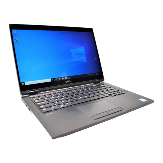
- Page 1 Dell Latitude 7389 2-in-1 Owner's Manual Regulatory Model: P29S Regulatory Type: P29S001...
- Page 2 A WARNING indicates a potential for property damage, personal injury, or death. © 2017 Dell Inc. or its subsidiaries. All rights reserved. Dell, EMC, and other trademarks are trademarks of Dell Inc. or its subsidiaries. Other trademarks may be trademarks of their respective owners.
-
Page 3: Table Of Contents
Contents 1 Working on your computer..........................6 Safety instructions................................6 Turning off your computer — Windows 10........................6 Before working inside your computer..........................6 After working inside your computer..........................7 2 Removing and installing components......................8 Screw size list..................................8 Recommended tools................................9 Micro Secure Digital (SD) Card............................ - Page 4 Installing the smart card cage..........................22 Heat Sink...................................22 Removing heat sink assembly...........................22 Installing heat sink assembly............................. 23 Display Assembly................................23 Removing the display assembly..........................23 Installing the display assembly..........................26 System Board................................... 26 Removing system board............................27 Installing system board.............................. 29 Real time clock (RTC)..............................29 Removing the real time clock (RTC)........................
- Page 5 USB drivers.................................62 System drivers................................63 Storage controller..............................64 Audio drivers................................65 Identifying Camera..............................66 Network adapter................................66 7 Troubleshooting............................68 Enhanced Pre-Boot System Assessment — ePSA diagnostics................68 Running the ePSA diagnostics..........................68 Diagnostic LED.................................68 Real Time Clock (RTC) reset............................69 8 Contacting Dell............................70 Contents...
-
Page 6: Working On Your Computer
Damage due to servicing that is not authorized by Dell is not covered by your warranty. Read and follow the safety instructions that came with the product. -
Page 7: After Working Inside Your Computer
CAUTION: To avoid damage to the computer, use only the battery designed for this particular Dell computer. Do not use batteries designed for other Dell computers. Connect any external devices, such as a port replicator or media base, and replace any cards, such as an ExpressCard. -
Page 8: Removing And Installing Components
Real time clock (RTC) • Keyboard • Palmrest Screw size list Table 1. Latitude 7389 - Screw size list Component M 2.5 x 2.5L M 2.5 x 4.0L M 2.0 x 3.0L M 2 x 2L M 2.0 x 2L M 2 x 1.7L... -
Page 9: Recommended Tools
Finger Print Bracket Touch pad Smart Card K/B to K/B plate K/B plate Bottom Door Assy System board Thermal Battery WLAN WWAN MSATA EDP Bracket USB Type C Recommended tools The procedures in this document require the following tools: • Phillips #0 screwdriver •... -
Page 10: Removing The Micro Sim Card Or The Micro Sim Card Tray
Removing the micro SIM card or the micro SIM card tray CAUTION: Removing the micro SIM card when the computer is on may cause data loss or damage the card. Ensure that your computer is turned off or the network connections are disabled. NOTE: Micro SIM card tray is available only for systems that are shipped with WWAN card. -
Page 11: Installing The Base Cover
Installing the base cover Align the base cover tabs to the slots on the edges of the computer. Press the edges of the cover until it clicks into place. Tighten the M2.5 x 5.0 captive screws to secure the base cover to the computer. Follow the procedure in After working inside your computer. -
Page 12: Installing Battery
Installing battery Insert the battery into the slot on the computer. Connect the battery cable to the connector on the system board. Replace the M 2 x 4L screws to secure the battery to the computer. Install the: base cover SD card Follow the procedure in After working inside your... -
Page 13: Installing The Nvme Ssd
Installing the NVMe SSD Insert the NVMe SSD card into the connector. Install the thermal bracket over the SSD card. Tighten the M2.0 x 3.0 screws to secure the SSD thermal bracket. Install the: battery NOTE: If you have not removed the battery, you must connect the battery cable to the system board. base cover MicroSD card Follow the procedure in... -
Page 14: Installing The Wlan Card
Disconnect the WLAN cables from the connectors on the WLAN card [3]. d Remove the WLAN card [4]. Installing the WLAN card Insert the WLAN card into the connector on the system board. Connect the WLAN cables to the connectors on the WLAN card. Place the metal bracket and replace the M2.0 x 3.0 screw to secure WLAN card to the computer. -
Page 15: Installing The Wwan Card
To remove the WWAN card: Remove the M2.0 x 3.0 screw that secures the metal bracket to the WWAN card . b Lift the metal bracket that secures the WWAN card . Disconnect the WWAN cables from the connectors on the WWAN card d Lift the WWAN card from the computer. -
Page 16: Installing The Power Board
Installing the power board Insert the power board into the slot. Replace the M2.0x3.0 screws to secure the power board to the computer. Connect the power board cable to the connector on the system board. Affix the coin cell battery in the slot on the computer. Install the: battery base cover... - Page 17 To release the speaker module: Disconnect the speaker cable from the connector on the system board [1]. b Un route the speaker cable from the retention clips and remove the tapes that secure the speaker cable [2]. To remove the speaker module: Un route the speaker cable by removing the tapes near the palm rest [1].
-
Page 18: Installing The Speaker Module
NOTE: You can use a plastic scribe to lift the speaker module from the computer. Installing the speaker module Place the speaker module into the slots on the computer. Route the speaker cable through the routing channel and secure it with the tapes. Connect the speaker cable to the connector on the system board. -
Page 19: Installing The Fingerprint Reader Board
b Disconnect the finger print reader cable from the fingerprint reader board and the USH board [2]. NOTE: The cable should be released so that it does not tear. Remove the M2 x 3 screw that secures the fingerprint reader bracket [3]. d Lift the fingerprint reader bracket from the fingerprint reader board [3]. -
Page 20: Removing The Led Board
Removing the LED board Follow the procedure in Before working inside your computer. Remove: Micro SD base cover battery To remove the LED board: Disconnect the LED board cable from the LED board [1]. b Remove the tape that secures the LED board to the touchpad panel [2]. Remove the M2 x 3 screws that secure the LED board [3]. -
Page 21: Smart Card Cage
Smart Card Cage Removing the smart card cage NOTE: Always remove the smart card from the smart card reader. Follow the procedure in Before working inside your computer. Remove: Micro SD base cover battery SSD card To disconnect the cables: Disconnect the smart card cable [1]. -
Page 22: Installing The Smart Card Cage
Installing the smart card cage Slide the smart card cage into the slot to align with the screw holders on the computer. Replace the M2.0 x 1.7 screws to secure the smart card cage to the computer. Affix the thermal pad on the SSD module. Affix the LED board cable and connect it to the LED board on the computer. -
Page 23: Installing Heat Sink Assembly
b Remove the M2.0 x 3.0 screws that secure the fan to the system board[2]. Remove the M2.0 x 3.0 screws that secure the heat sink to the system board [3]. d Lift the heat sink assembly from the system board. Installing heat sink assembly Align the heat sink assembly with screw holders on the system board. - Page 24 battery WLAN card WWAN card Peel the tapes that secure the antenna cables and un route the cables from the routing clips. Disconnect the : IR camera and touchscreen cable [1]. b Remove the M 2 x 1.7L screws that secure the eDP bracket and lift it away from the computer [2]. Disconnect the eDP cable from the system board [3].
- Page 25 Lift the base of the computer away from the display assembly. To remove the display assembly: Place the base of the computer with the display assembly at 270 degrees (laptop mode) or 90 degrees (tablet mode). NOTE: If the system is used as a laptop, then display assembly should be at 270 degrees and for a fully closed tablet configuration, the display should be at 90 degrees.
-
Page 26: Installing The Display Assembly
Lift the display assembly away from the computer [2]. Installing the display assembly Place the base of the computer on a flat surface. Install the display assembly by aligning it with the display hinge screw holders. Replace the M2.5 x 4.0 screws to secure the display assembly. Close the display assembly and flip the computer. -
Page 27: Removing System Board
Removing system board Follow the procedure in Before working inside your computer. Remove the: Micro SD SIM card tray base cover battery SSD card WLAN card WWAN card heatsink assembly Disconnect the following cables from the system board . touchpad cable b USH cable LED board cable Disconnect the eDP cable:... - Page 28 Peel the tapes that secure antenna cables and un route the cables from the routing clips. To remove the system board: Remove the M2.0 x 4L screws from the USB Type-C bracket [1]. b Lift the USB Type-C bracket from the Type-C module [2]. Remove the M2.0 x 3.0 screws that secure the system board to the computer [3].
-
Page 29: Installing System Board
Installing system board Align the system board with the screw holders on the computer. Replace the M2.0 x 3.0 screws to secure the system board to the computer. Place the USB Type-C bracket on the Type-C module. Replace the M 2.0 x 4L screws to secure the USB Type-C bracket to the Type-C module. Route the antenna cable through the routing clips and affix the tapes to secure the antenna cables. -
Page 30: Removing The Real Time Clock (Rtc)
Removing the real time clock (RTC) Follow the procedure in Before working inside your computer. Remove the: mircro SD card SIM card tray NOTE: SIM Card tray is available only if your computer is shipped with a WWAN card. base cover battery SSD card WLAN card... -
Page 31: Keyboard
Follow the procedure in After working inside your computer. RTC is located on the system board and hence system board must be installed after the installation of the RTC. Keyboard Removing keyboard assembly NOTE: The keyboard and the keyboard tray together are called the keyboard assembly. Follow the procedure in Before working inside your computer. -
Page 32: Removing Keyboard From The Keyboard Tray
b Lift the keyboard from the chassis [2]. Removing keyboard from the keyboard tray Follow the procedure in Before working inside your computer. Remove the keyboard Remove the keyboard from the keyboard support tray: Remove the M2.0 x 2.0 screws that secure the keyboard to the keyboard assembly [1]. b Lift the keyboard away from the keyboard support tray [2]. -
Page 33: Installing Keyboard To The Keyboard Tray
Installing keyboard to the keyboard tray Align the keyboard with the screw holders on the keyboard tray. Tighten the M2.0 x 2.0 screws to secure the keyboard to the keyboard tray. Install the keyboard. Installing keyboard assembly NOTE: The keyboard and the keyboard tray together are called the keyboard assembly. Align the keyboard assembly with the screw holders on the chassis. -
Page 34: Palmrest
Palmrest Replacing palm rest Follow the procedure in Before working inside your computer. Remove the: base cover battery SSD module WLAN card WWAN card power board heat sink assembly LED board speaker smart card cage display assembly system board keyboard The component you are left with is the palmrest. - Page 35 speaker LED board heat sink power board WLAN card WWAN card PCIe SSD battery base cover Follow the procedure in After working inside your computer. Removing and installing components...
-
Page 36: Technology And Components
Technology and components This chapter details the technology and components available in the system. Topics: • USB features • HDMI 1.4 USB features Universal Serial Bus, or USB, was introduced in 1996. It dramatically simplified the connection between host computers and peripheral devices like mice, keyboards, external drivers, and printers. -
Page 37: Applications
commonly known as USB 2.0 and 1.1 respectively, the slower modes still operate at 480Mbps and 12Mbps respectively and are kept to maintain backward compatibility. USB 3.0/USB 3.1 Gen 1 achieves the much higher performance by the technical changes below: •... -
Page 38: Compatibility
Compatibility The good news is that USB 3.0/USB 3.1 Gen 1 has been carefully planned from the start to peacefully co-exist with USB 2.0. First of all, while USB 3.0/USB 3.1 Gen 1 specifies new physical connections and thus new cables to take advantage of the higher speed capability of the new protocol, the connector itself remains the same rectangular shape with the four USB 2.0 contacts in the exact same location as before. - Page 39 • Audio HDMI supports multiple audio formats from standard stereo to multichannel surround sound • HDMI combines video and multichannel audio into a single cable, eliminating the cost, complexity, and confusion of multiple cables currently used in A/V systems • HDMI supports communication between the video source (such as a DVD player) and the DTV, enabling new functionality Technology and components...
-
Page 40: System Specifications
System specifications NOTE: Offerings may vary by region. The following specifications are only those required by law to ship with your computer. For more information about the configuration of your computer, go to Help and Support in your Windows operating system and select the option to view information about your computer. -
Page 41: Display Specifications
Feature Specification • Intel Core i5-7200U Processor (Dual Core, 2.5GHz up to 3.1GHz, 3M cache, 15W) • Intel Core i5-7300U Processor (Dual Core, 2.6GHz up to 3.5GHz, 3M cache, 15W), vPro • Intel Core i7-7600U Processor (Dual Core, 2.8GHz up to 3.9GHz, 4M cache, 15W), vPro Display specifications Feature Specification... -
Page 42: Storage Options
Feature Specification External interface Microphone-in, stereo headphones, and universal audio jack Speakers Internal speaker 2 W (RMS) per channel amplifier Volume controls Volume control buttons and Hot keys Storage options Feature Specification Storage options • 256 GB M.2 2280 PCIeSSD •... -
Page 43: Ports And Connector Specifications
Feature Specification Sensor resolution 385 dpi Sensor size 11.9 mm x 11.9 mm Sensor pixel size 180x180 pixels Ports and connector specifications Feature Specification Audio • Universal audio jack • Volume buttons Video HDMI 1.4 • One USB 3.1 Gen 1 •... -
Page 44: Ir Camera Specifications
IR camera specifications Feature Specification Type VGA IR camera Sensor type CMOS sensor Resolution: Motion Win Hello Recognition Video Imaging Rate up to 15- fps AC adapter specifications Feature Specification Type 45 W, 65 W, 90 W with USB Type-C Input voltage 100 V AC to 240 V AC Input current—... -
Page 45: Battery Specifications
Feature Specification Dimensions—65 W • Height—99 mm (3.90 inches) • Width—66 mm (2.60 inches) • Depth—22 mm (0.87 inch) Dimensions—90W • Height-130 mm (5.12 inches) • Width-66 mm (2.60 inches) • Depth-22 mm (0.87 inch) Temperature range 0°C to 40°C (32°F to 104°F) —Operating Temperature range –40°C to 70°C (–40°F to 158°F) -
Page 46: Docking Option
Discharge: 0°C to 70°C (32°F to 158°F) Non-operating - 20°C to 65°C (- 4°F to 149°F) Coin cell battery 3 V CR2032 lithium coin cell Docking Option Feature Specification Type Dell Dock WD15 Active Pen Feature Specification Type Wacom PCAP technology Physical specifications Feature Specification Front height 0.46 inch (11.79 mm) - Page 47 Relative humidity Specifications —maximum Operating 20 % to 80 % (non-condensing) Storage 5% to 95% (non-condensing) Altitude— Specifications maximum Operating 0 m to 3048 m (0 to 10,000 ft) 0° to 40°C (32° to 104°F) Non-operating 0 m to 10668 m (0 to 35,000 ft) Airborne G2 or lower as defined by ISA S71.04–1985 contaminant level...
-
Page 48: System Setup
Boot menu Press <F12> when the Dell logo appears to initiate a one-time boot menu with a list of the valid boot devices for the system. Diagnostics and BIOS Setup options are also included in this menu. The devices listed on the boot menu depend on the bootable devices in the system. -
Page 49: Navigation Keys
• BIOS Setup • BIOS Flash Update • Diagnostics • Change Boot Mode Settings Navigation keys NOTE: For most of the System Setup options, changes that you make are recorded but do not take effect until you restart the system. Keys Navigation Up arrow... -
Page 50: System Configuration Screen Options
Option Description • Onboard NIC Boot sequence • Windows boot manager options • WindowsIns Boot list options • Legacy • UEFI—selected by default Advanced Boot This option allows you the legacy option ROMs to load. By default, the Enable Legacy Option ROMs is disabled. Options Enable Attempt Legacy Boot is disabled by default. - Page 51 A USB Keyboard and/or mouse connected to the platform's USB ports will continue to function within BIOS Setup if the "Enable External USB Port" option is disabled. Dell Type-C Dock This section allows connection to the Dell WD and TB family of docks (Typr-C docks) independent of USB and Configuration Thunderbolt Adapter configuration settings.
-
Page 52: Video Screen Options
Option Description Keyboard Backlight The Keyboard Backlight Timeout dims out with the Battery option. The main keyboard illumination feature is not Timeout on Battery affected. Keyboard Illumination will continue to support the various illumination levels. This field has an effect when the backlight is enabled. -
Page 53: Intel Software Guard Extensions Screen Options
Option Description • Disabled • Enabled Default setting: Enabled. Expert Key This option enables or disables the Expert Key management feature. management • PK—enabled by default • • • Default setting: Enabled Intel software guard extensions screen options Option Description Intel SGX Enable This field specifies you to provide a secured environment for running code/storing sensitive information in the context of the main OS. -
Page 54: Power Management Screen Options
• Enable USB Wake Support • Wake on Dell USB-C dock Default setting: The option is disabled. Wake on WLAN Allows you to enable or disable the feature that powers on the computer from the Off state when triggered by a LAN signal. -
Page 55: Post Behavior Screen Options
• Adaptive—enabled by default Configuration • Standard—Fully charges your battery at a standard rate. • ExpressCharge—The battery charges over a shorter time using Dell’s fast charging technology This option is enabled by default. • Primarily AC use • Custom If Custom Charge is selected, you can also configure Custom Charge Start and Custom Charge Stop. -
Page 56: Manageability
Option Description • Serial Mouse • PS2 Mouse • Touchpad/PS-2 Mouse: This option is enabled by default. Numlock Enable Allows you to enable the Numlock option when the computer boots. Enable Network. This option is enabled by default. Fn Key Emulation Allows you to set the option where the Scroll Lock key is used to simulate the Fn key feature. -
Page 57: Virtualization Support Screen Options
Virtualization support screen options Option Description Virtualization This field specifies whether a virtual Machine Monitor (VMM) can utilize the conditional hardware capabilities provided by Intel Virtualization Technology. Enable Intel Virtualization Technology—enabled by default. VT for Direct I/O Enables or disables the Virtual Machine Monitor (VMM) from utilizing the additional hardware capabilities provided by Intel®... -
Page 58: System Logs Screen Options
If BitLocker is enabled, it must be suspended prior to updating the system BIOS, and then re-enabled after the BIOS update is completed. Restart the computer. Go to Dell.com/support. • Enter the Service Tag or Express Service Code and click Submit. -
Page 59: System And Setup Password
NOTE: It is recommended not to update the BIOS version for more than three revisions. For example: If you want to update the BIOS from 1.0 to 7.0, then install version 4.0 first and then install version 7.0. System and setup password You can create a system password and a setup password to secure your computer. - Page 60 The computer reboots. System setup...
-
Page 61: Software
After the download is complete, navigate to the folder where you saved the driver file. Double-click the driver file icon and follow the instructions on the screen. Device drivers This section provides information about device drivers for Dell Latitude 7389. Display Adapter Verify if the display adapter driver is already installed in the system. -
Page 62: Usb Drivers
USB drivers Verify if the USB drivers are already installed in the system. Software... -
Page 63: System Drivers
System drivers Verify if the system drivers are already installed in the system. continued Software... -
Page 64: Storage Controller
Storage controller Verify if the storage controller drivers are already installed in the system. Software... -
Page 65: Audio Drivers
Audio drivers Verify if the audio drivers are already installed in the system. Software... -
Page 66: Identifying Camera
Identifying Camera Under Device Manager expand Imaging devices. Network adapter Verify if the network adapter drivers are already installed in the system. Software... - Page 67 Software...
-
Page 68: Troubleshooting
Running the ePSA diagnostics Power-on the computer. As the computer boots, press the F12 key as the Dell logo appears. On the boot menu screen, select the Diagnostics option. Click the arrow key at the bottom left corner. -
Page 69: Real Time Clock (Rtc) Reset
Real Time Clock (RTC) reset The Real Time Clock (RTC) reset function allows you or the service technician to recover the recently launched model Dell Latitude and Precision systems from select No POST/No Boot/No Power situations. You can initiate the RTC reset on the system from a power off state only if it is connected to AC power. -
Page 70: Contacting Dell
Dell product catalog. Dell provides several online and telephone-based support and service options. Availability varies by country and product, and some services may not be available in your area. To contact Dell for sales, technical support, or customer service issues: Go to Dell.com/support.
Need help?
Do you have a question about the Latitude 7389 and is the answer not in the manual?
Questions and answers