HPE MSR2004-48 Installation Manual
Hide thumbs
Also See for MSR2004-48:
- Command reference manual (548 pages) ,
- Command reference manual (35 pages)

Subscribe to Our Youtube Channel
Related Manuals for HPE MSR2004-48


Summary of Contents for HPE MSR2004-48
-
Page 1: Installation Guide
HPE FlexNetwork MSR2000 Routers Installation Guide Part number: 5998-6483R Document version: 6W104-20160519... -
Page 2: Acknowledgments
© Copyright 2016 Hewlett Packard Enterprise Development LP The information contained herein is subject to change without notice. The only warranties for Hewlett Packard Enterprise products and services are set forth in the express warranty statements accompanying such products and services. Nothing herein should be construed as constituting an additional warranty. Hewlett Packard Enterprise shall not be liable for technical or editorial errors or omissions contained herein. -
Page 3: Table Of Contents
Contents Acknowledgments ············································································· i Preparing for installation ···································································· 1 Safety recommendations ············································································································· 1 Safety symbols ··················································································································· 1 General safety recommendations ··························································································· 1 Electricity safety ·················································································································· 1 Examining the installation site ······································································································· 2 Temperature and humidity ····································································································· 2 ... - Page 4 Appendix A Chassis views and technical specifications ·························· 36 Chassis views ························································································································· 36 MSR2003 ························································································································ 36 MSR2004-24 ···················································································································· 37 MSR2004-48 ···················································································································· 37 Power supplies ························································································································ 38 AC power supply ··············································································································· 38 DC power supply ··············································································································· 39 ...
-
Page 5: Preparing For Installation
Preparing for installation The HPE MSR2000 Router Series includes the models in Table Table 1 HPE MSR2000 Router Series models Router model Product code HPE description MSR2003 JG411A HPE MSR2003 Router BJNGA-BB0009 MSR2004-24 JG734A HPE MSR2004-24 Router BJNGA-BB0031 MSR2004-48 JG735A... -
Page 6: Examining The Installation Site
Examining the installation site The routers can only be used indoors. To make sure the router operates correctly and to prolong its service lifetime, the installation site must meet the following requirements. Temperature and humidity You must maintain the temperature and humidity in the equipment room at an acceptable level. •... -
Page 7: Esd Prevention
Figure 1 Airflow through the MSR2000 chassis To ensure good ventilation, the following requirements must be met: • The inlet and outlet air vents are not blocked, and leave at least 10 cm (3.94 in) of clearance. • The installation site has a good cooling system. ESD prevention To prevent electrostatic discharge (ESD), follow these guidelines: •... -
Page 8: Lightning Protection
• Take measures against interference from the power grid. • Do not use the router together with the grounding equipment or lightning-prevention equipment of power equipment, and keep the router far away from them. • Keep the router far away from high-power radio launchers, radars, and equipment with high frequency or high current. -
Page 9: Pre-Installation Checklist
Pre-installation checklist Table 5 Pre-installation checklist Item Requirements Result • There is a minimum clearance of 10 cm (3.94 in) around the inlet and outlet air vents for heat dissipation of the router chassis. Ventilation • A good ventilation system is available at the installation site. - Page 10 Item Requirements Result • The rack is equipped with a good ventilation system. • The rack is sturdy enough to support the weight Rack-mounting of the router and installation accessories. requirements • The size of the rack is appropriate for the router. •...
-
Page 11: Installing The Router
Installing the router WARNING! To avoid injury, do not touch bare wires, terminals, or parts with high-voltage hazard signs. IMPORTANT: • The barcode on the router chassis contains product information that must be provided to local sales agent before you return a faulty router for service. •... - Page 12 Figure 2 Installation flowchart Start W orkbench Rack Determine the mounting location Mount to a rack Mount to a workbench Ground the router Install interface modules Connect the router to the network Connect the router to a console terminal Connect the power cord Verify the installation Power on the router Troubleshoot the router...
-
Page 13: Installing The Router
Installing the router Mounting the router on a workbench IMPORTANT: • Ensure good ventilation and 10 cm (3.94 in) of clearance around the chassis for heat dissipation. • Avoid placing heavy objects on the router. To mount the router on a workbench: Make sure the workbench is clean, stable, and correctly grounded. -
Page 14: Mounting The Router To A Rack
Mounting the router to a rack Rack-mounting clearance requirements Figure 5 MSR2003 rack-mounting clearance requirement 60 mm (2.36 in) Mounting bracket E1 cable Power cord 303.5 mm (11.95 in) 60 mm (2.36 in) - Page 15 Figure 6 MSR2004-24 rack-mounting clearance requirement...
- Page 16 Figure 7 MSR2004-48 rack-mounting clearance requirement Front mounting bracket Power cord E1 cord Ethernet network cable 403.5 mm (15.89 in) 60 mm 45 mm (2.36 in) (1.77 in) Table 6 Rack-mounting clearance requirements Model Router dimensions Requirements for the rack •...
- Page 17 Model Router dimensions Requirements for the rack 45 mm (1.77 in) for connecting an rear door—A minimum of 460 mm Ethernet network cable (18.11 in) 60 mm (2.36 in) for connecting an E1 cable Mounting the router in a rack WARNING! The mounting brackets can only support the weight of the router.
- Page 18 Figure 9 Installing cage nuts Repeat step 3 to install other cage nuts to all the marked positions on the rack posts. Attach the mounting brackets to the two sides of the chassis and fasten the screws.. Figure 10 Attaching the front mounting brackets Place the chassis on the rack and use M6 screws to attach the mounting brackets to the rack posts..
-
Page 19: Grounding The Router
Figure 11 Securing the router to the rack Grounding the router WARNING! Correctly connecting the router grounding cable is crucial to lightning protection and EMI protection. IMPORTANT: The resistance reading should be smaller than 5 ohms between the chassis and the ground. Grounding the router through the rack IMPORTANT: Make sure the rack is correctly grounded before grounding the router. - Page 20 Figure 12 Connecting the grounding cable to the grounding hole of the router Figure 13 Grounding the router through the rack (1)
-
Page 21: Grounding The Router With A Grounding Strip
Figure 14 Grounding the router through the rack (2) Grounding the router with a grounding strip If a grounding strip is available at the installation site, connect the grounding cable to the grounding strip. Follow the same procedures in "Grounding the router through the rack"... -
Page 22: Grounding The Router With A Grounding Conductor Buried In The Earth Ground
Figure 15 Grounding the router with a grounding strip Grounding the router with a grounding conductor buried in the earth ground If the installation site has no grounding strips, but earth ground is available, hammer a 0.5 m (1.64 ft) or longer angle iron or steel tube into the earth ground to serve as a grounding conductor. -
Page 23: Installing A Dsic
Figure 16 Removing the filler panel Figure 17 Installing a SIC Installing a DSIC CAUTION: DSICs are not hot swappable. Make sure the router is powered off before installing a DSIC. The MSR2004 router does not support DSICs. To install a DSIC: Remove the screws on the filler panel on slot 1 and slot 2 of the router to remove the filler panel. -
Page 24: Connecting The Router To The Network
Connecting the router to the network Connect the router to the network before powering on the router. This section describes how to connect the router to the network through Ethernet cables. For other connection methods, see HPE MSR Router Series Interface Module Guide. -
Page 25: Logging In To The Router
Figure 21 Connecting the router to a PC Logging in to the router At the first login, you can access an MSR2003 router through the console port by using a console cable or through the USB console port by using a USB cable. You can only access an MSR2004 router through the console port by using a console cable. -
Page 26: Connecting A Usb Cable
Connecting a USB cable IMPORTANT: Download and install the USB console driver program before configuring the device when you connect the device through a USB console cable. To connect a USB cable: Connect the USB port to the PC. Connect the other end to the USB console port of the router. Figure 23 Connecting a USB cable Click the following link, or copy it to the address bar on the browser to log in to download page of the USB console driver, and download the driver. - Page 27 Figure 24 Device driver installation wizard Click Continue Anyway if the following dialog box appears. Figure 25 Software installation Click Finish.
-
Page 28: Setting Terminal Parameters
Installing power supplies CAUTION: Do not install AC and DC power supplies on the same router. The MSR2004-48 router supports both AC and DC power supplies. The power supplies are hot swappable on the MSR2004-48 router. To install a power supply: Loosen the captive screws on the filler panel in the target slot with a Phillips screwdriver to remove the filler panel from the slot. -
Page 29: Connecting A Power Cord
Use a Phillips screwdriver to fasten the captive screws on the two sides of the power supply. Figure 27 Installing an AC power supply for the MSR2004-48 router Figure 28 Installing a DC power supply for the MSR2004-48 router Connecting a power cord The power cords in the figures are for illustration only. -
Page 30: Connecting A Dc Power Cord
When you connect a power cord, always identify the polarity symbol on its wires. You can connect a DC power cord to only the MSR2004-48 router. To connect a DC power cord: Make sure the router is correctly grounded, and the power switch on the router is in the OFF position. -
Page 31: Verifying The Installation
(– or L–) to the negative terminal (–) and the positive wire (+ or M/N) to the positive terminal (+). Figure 31 Connecting a DC power cord to the MSR2004-48 router Verifying the installation After you complete the installation, verify that: •... -
Page 32: Displaying Boot Information
System is starting... Press Ctrl+D to access BASIC-BOOTWARE MENU... Booting Normal Extended BootWare The Extended BootWare is self-decompressing..Done. **************************************************************************** HPE MSR2003 BootWare, Version 1.60 **************************************************************************** Copyright (c) 2010-2015 Hewlett Packard Enterprise Development LP Compiled Date : Dec 18 2015 CPU ID... -
Page 33: Examining The Router After Power-On
Configuring basic settings for the router After the router is powered on for the first time, configure the basic settings for the router. For more information, see HPE MSR Routers Fundamentals Configuration Guide (V7) and HPE MSR Routers Fundamentals Command Reference (V7). -
Page 34: Replacement Procedure
Replacement procedure Replacing a power supply The power supplies are hot swappable. To replace a power supply: Use a Phillips screwdriver to remove the captive screws on the power supply. Holding the power supply handle with one hand and supporting the bottom of the power supply with the other, gently pull the power supply out from the slot. -
Page 35: Replacing A Dsic
Figure 34 Installing a filler panel Replacing a DSIC Completely loosen the captive screws of the DSIC. Gently pull the DSIC out along the slide rails. If you need to install a DSIC or SICs, see "Installing the router" for the installation procedure. To install filler panels, proceed to steps 3 and 4. - Page 36 Figure 37 Installing filler panels...
-
Page 37: Troubleshooting
If the problem persists, contact Hewlett Packard Enterprise Support. Troubleshooting fan failures Symptom After the router starts up, the following error message appears on the configuration terminal: %Jun 22 16:11:37:485 2015 HPE DEV/4/FAN FAILED: Fan 1 failed. Solution Verify that the fans are in position. -
Page 38: No Display On The Configuration Terminal
No display on the configuration terminal Symptom After the router is powered on, the console terminal does not display anything. Solution Follow these steps to troubleshoot the configuration system failures first: Verify that the power supply system is operating correctly. Verify that the console cable is properly connected. -
Page 39: Restoring The Factory Settings
Verify that the cable is correctly connected. Restoring the factory settings Scenario 1 Symptom When you replace the router, the router password is lost. As a result, you cannot log in to the router and do not know the router configuration. Solution Because the router is replaced, you do not need to save the configuration of the router. -
Page 40: Appendix A Chassis Views And Technical Specifications
Appendix A Chassis views and technical specifications Chassis views The following figures are for illustration only. MSR2003 Figure 38 Front view (1) AC-input power receptacle (2) Power switch (3) Gigabit Ethernet port (GE0) (4) Gigabit Ethernet port (GE1) (5) Console/AUX port (CON/AUX) (6) USB console port (CON) (7) USB port Figure 39 Rear view... -
Page 41: Msr2004-24
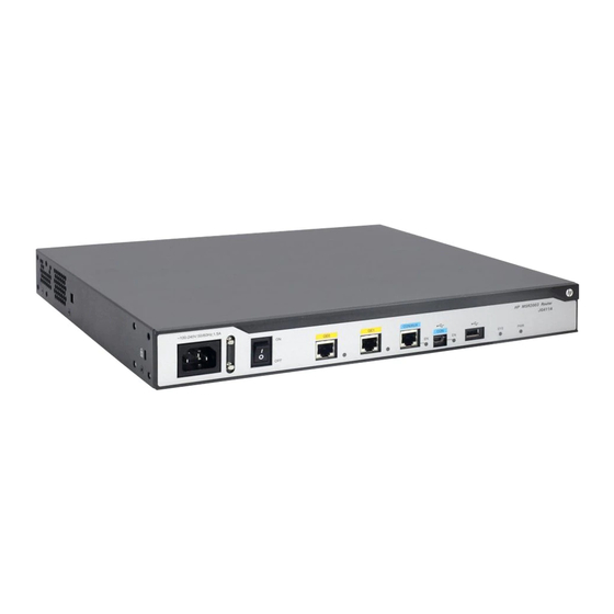
(2) SIC slot (Slot 3) (3) SIC slot (Slot 2) (4) SIC slot (Slot 1) (5) Grounding terminal MSR2004-48 Figure 42 Front view (1) Gigabit Ethernet port (GE3 to (2) Gigabit Ethernet port (GE19 to (3) Gigabit Ethernet port (GE35... -
Page 42: Power Supplies
Power supplies One power supply can meet the power requirement of the router. You can install two power supplies for redundancy. AC power supply Figure 44 AC power supply for the MSR2004-48 router (1) Captive screw (2) Fan (3) Power receptacle... -
Page 43: Dc Power Supply
DC power supply Figure 45 DC power supply for the MSR2004-48 router (1) Fan (2) Captive screw (3) Captive screw (4) Power receptacle Technical specifications Table 7 Technical specifications Item MSR2003 MSR2004-24 MSR2004-48 Console/AUX port USB console port USB port... - Page 44 Item MSR2003 MSR2004-24 MSR2004-48 • Rated voltage range—–48 VDC to DC power –60 VDC supply • Rated power—150 W Operating 0°C to 45°C (32°F to 113°F) temperature Relative humidity 5% to 90% (noncondensing...
-
Page 45: Appendix B Leds
Appendix B LEDs Panel LEDs Figure 46 MSR2003 LEDs (1) Gigabit Ethernet port LED (2) Gigabit Ethernet port LED (3) Console port LED (GE0) (GE1) (4) USB console port LED (5) System status LED (SYS) (6) Power supply LED (PWR) Figure 47 MSR2004-24 LEDs (1) Gigabit Ethernet port LED (GE3 to (2) Power supply LED (PWR) -
Page 46: Led Description
Figure 48 MSR2004-48 LEDs (1) Gigabit Ethernet port LED (2) Power supply LED (PWR2) (3) Power supply LED (PWR1) (GE3 to GE50) (4) System status LED (SYS) (5) Gigabit Ethernet port LED (6) Gigabit Ethernet port LED (GE1) (GE2) (7) Gigabit Ethernet port LED (GE0) - Page 47 State Description Flashing yellow Data is being received or transmitted at 10/100 Mbps. No link is present. Steady green A 1000 Mbps link is present. Flashing green Data is being received or transmitted at 1000 Mbps. Gigabit Ethernet port Steady yellow A 10/100 Mbps link is present.
-
Page 48: Appendix C Slot Arrangement
Appendix C Slot arrangement The routers provide slots for SICs. A DSIC can be installed if you remove the slot divider between two SIC slots.. The slot number of fixed ports on the router is 0. Table 8 Slot arrangement on the router Slot arrangement Interface name •... -
Page 49: Document Conventions And Icons
Document conventions and icons Conventions This section describes the conventions used in the documentation. Port numbering in examples The port numbers in this document are for illustration only and might be unavailable on your device. Command conventions Convention Description Bold text represents commands and keywords that you enter literally as shown. Boldface Italic text represents arguments that you replace with actual values. -
Page 50: Network Topology Icons
Network topology icons Convention Description Represents a generic network device, such as a router, switch, or firewall. Represents a routing-capable device, such as a router or Layer 3 switch. Represents a generic switch, such as a Layer 2 or Layer 3 switch, or a router that supports Layer 2 forwarding and other Layer 2 features. -
Page 51: Support And Other Resources
Support and other resources Accessing Hewlett Packard Enterprise Support • For live assistance, go to the Contact Hewlett Packard Enterprise Worldwide website: www.hpe.com/assistance • To access documentation and support services, go to the Hewlett Packard Enterprise Support Center website: www.hpe.com/support/hpesc Information to collect •... -
Page 52: Websites
For more information and device support details, go to the following website: www.hpe.com/info/insightremotesupport/docs Documentation feedback Hewlett Packard Enterprise is committed to providing documentation that meets your needs. To help us improve the documentation, send any errors, suggestions, or comments to Documentation Feedback (docsfeedback@hpe.com). When submitting your feedback, include the document title,... - Page 53 part number, edition, and publication date located on the front cover of the document. For online help content, include the product name, product version, help edition, and publication date located on the legal notices page.
-
Page 54: Index
Index logging in, console terminal power-on examination, connecting power cord, accessories (installation), Appendix DSIC A, chassis views and technical replacing, specifications, B, LEDs, electrical C, slot arrangement, EMI prevention, fan failure, boot information, grounding router through rack, grounding router with buried grounding conductor, cable grounding router with grounding strip,... - Page 55 interface module DSIC installation, hardware installing DSIC, grounding router through rack, installing SIC, grounding router with buried grounding module installation, conductor, replacing DSIC, grounding router with grounding strip, replacing SIC, grounding the router, SIC installation, rack-mounting clearance requirements, replacement procedures, replacing DSIC, replacing SIC, power-on examination,...
- Page 56 preparing for installation, troubleshooting connection failure, cleanness, troubleshooting fan failure, cooling system, troubleshooting garbled terminal display, electricity safety, troubleshooting interface module failure, EMI, troubleshooting no response from serial port, ESD prevention, troubleshooting no terminal display, examing the installation site, troubleshooting power supply failure, general satefy recommendations, lightning protection, rack...
- Page 57 AC power supply specifications, verfication CF card memory, power-on, CF card slot, verifying installation, chassis dimensions, chassis views, workbench (router installation), CON/AUX port, Gigabit Ethernet port, LED description, LEDs, memory, operating temperature, panel LEDs, relative humidity, SIC/DSIC slot, slot arrangement, USB console port, USB port, terminal...
Need help?
Do you have a question about the MSR2004-48 and is the answer not in the manual?
Questions and answers