Table of Contents
Advertisement
Quick Links
Advertisement
Table of Contents

Related Manuals for Axio MET AX-572


Summary of Contents for Axio MET AX-572
- Page 1 Digital Multimeter AX-572 Instruction manual...
- Page 2 1. SUMMARIZE The meter is a stable multimeter with 40mm LCD display, driven by battery. It's widely used on measuring DCV, ACV, DCA, ACA, resistance, capacitance, diode, transistor, continuity test ,temperature auto power off /on and LCD back – light . It’s an ideal tool for lab, factory and family. 2.
- Page 3 1-4.Sampling rate: approx. 3 times/second. 1-5.Over range indication: the MSD displays“1” or“-1”. 1-6.Low battery indication:“ ” appears. 1-7.Operation environment: (0~40) ,R.H.<80% . 1-8.Power:9V×1(NEDA1604/6F22 or equivalent model). 1-9.Size: 175×93×55mm 1-10.Weight: approx. 400g(including battery). 3.2. . . . TECHNICAL CHARACTERISTIC 2-1.Accuracy:±(a%×rdg+d) at (23±5) ,R.H.<75%,one year guaranteed from the production date. 2-2.
- Page 4 2-2-1. DCV RESOLUTI RANGE ACCURACY 200mV 100uV ±(0.5%+3) 10mV 200V 100mV 1000V ±(0.8%+10) Input resistance:10M for all ranges. Overload protection: 250V DV or AC peak value at 200mV range. 1000V DC or AC peak value at other ranges. 2-2-2. ACV RANGE ACCURACY RESOLUTION...
- Page 5 2-2-3.DCA RANGE ACCURACY RESOLUTION 20uA 0.01uA ±(0.8%+10) 200mA ±(1.2%+8) 100uA ±(2.0%+5) 10mA Max. input volt drop: 200Mv Max. input current: 20A(the test time should be within 10 seconds) Overload protection: 0.2A/250V;20A/250V fast-blown fuse 2-2-4.ACA RANGE ACCURACY RESOLUTION ±(1.0%+15) 200mA ±(2.0%+5) 100uA ±(3.0%+10) 10mA...
- Page 6 2-2-5. RESISTANCE ( ) RANGE ACCURACY RESOLUTION ±(0.8%+5) ±(0.8%+3) 200k ±(1.0%+25) Open voltage: less than 0.7V Overload protection: 250V DC and AC peak value NOTE: at 200 range, the test leads should be short-circuit, and measure the down-lead resistance, then, subtract from the real measuring. WARNING: DO NOT input any voltage at resistance range for safety! 2-2-6.
- Page 7 2-2-7.DIODE AND CONTINUITY TEST Range Displaying value Test condition The positive DC current is approx. Positive voltage drop of 1mA,negative diode voltage is approx. Buzzer sounds , the open voltage is resistance is less than approx. 3V (70±20) Overload protection: 250V DC or AC peak value Warning: DO NOT input any voltage at this range for safety! 2-2-8.
-
Page 8: Operation
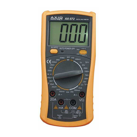
4. OPERATION 4.1 Front panel description 1. Model 2. LCD display 3. Shine diode 4 .range knob 5 .20A current test jack 6.“-” pole jack for capacitance, temp. and test accessory and less than 200mA current test jack. 7.“+”pole jack for capacitance, temp. test accessory and GND. 8. -
Page 9: Dcv Measurement
4.2 DCV MEASUREMENT 1.Insert the black test lead to “COM” jack, the red one to V/ jack. 2.Set the range knob to a proper DCV range, connect the test leads across to the circuit under tested, the polarity and voltage of the point which red lead connect will display on LCD. NOTE: 1.If the measured voltage is unsure beforehand, should set the range knob to the highest range, then, switch to a proper range according to the displayed value. -
Page 10: Resistance Measurement
4.5 ACV MEASUREMENT 1.Insert the black test lead to “COM” jack and the red one to“mA” jack(max. 200mA),or insert the red one to “20A” jack(max. 20A). 2.Set the range knob to a proper ACA range; connect the test leads across to the circuit under tested. NOTE: 1.If the measured current range is unsure beforehand, should set the range knob to the highest range, then set to a proper range according to the displayed value. -
Page 11: Diode And Continuity Test
NOTE: 1.If the capacitance range under measured is unsure beforehand, should set the range knob to the highest range, then, set to a proper range according to the displayed value. 2.If LCD displays“1” , it means over range, should set the range knob to a higher range. 3.Before measuring, LCD display might not be zero, the residual reading will be decreased gradually and could be disregarded. -
Page 12: Maintenance
disappear and exit the status of auto power-off . If need auto power off ,Press LCD backlight key for 2 seconds, LCD screen showed “APO” , in circulation . 5.MAINTENANCE DO NOT try to verify the circuit for it’s a precision meter. 1.Beware of waterproof, dustproof and shockproof.
Need help?
Do you have a question about the AX-572 and is the answer not in the manual?
Questions and answers