
Subscribe to Our Youtube Channel
Related Manuals for Extron electronics DTP T SW4 HD 4K


Summary of Contents for Extron electronics DTP T SW4 HD 4K
- Page 1 User Guide DTP Systems DTP T SW4 HD 4K Four Input Switcher with Integrated DTP Transmitter 68‑2916‑01 Rev. B 09 17...
-
Page 2: Safety Instructions
Safety Instructions Safety Instructions • English Istruzioni di sicurezza • Italiano WARNING: This symbol, , when used on the product, is intended to Il simbolo, , se usato sul prodotto, serve ad avvertire l’utente AVVISO: alert the user of the presence of uninsulated dangerous voltage within the della presenza di tensione non isolata pericolosa all’interno del contenitore product’s enclosure that may present a risk of electric shock. - Page 3 ついては、 エクス トロンのウェブサイ ト より 『Extron Safety www.extron.com and Regulatory Compliance Guide』 (P/N 68-290-01) をご覧ください。 Copyright © 2017 Extron Electronics. All rights reserved. Trademarks All trademarks mentioned in this guide are the properties of their respective owners. The following registered trademarks( ®...
- Page 4 FCC Class A Notice This equipment has been tested and found to comply with the limits for a Class A digital device, pursuant to part 15 of the FCC rules. The Class A limits provide reasonable protection against harmful interference when the equipment is operated in a commercial environment.
-
Page 5: Conventions Used In This Guide
Conventions Used in this Guide Notifications The following notifications are used in this guide: CAUTION: Risk of minor personal injury. ATTENTION : Risque de blessure mineure. ATTENTION: • Risk of property damage. • Risque de dommages matériels. NOTE: A note draws attention to important information. A tip provides a suggestion to make working with the application easier. -
Page 7: Table Of Contents
Contents Introduction ..........1 Product Configuration Software ....29 About this Guide ..........1 Downloading PCS Software ......29 About the DTP T SW4 HD 4K Switcher ....1 Configuring the DTP T SW4 HD 4K with PCS ..30 Features .............. 2 Input/Output Configuration Menu....31 EDID Minder Menu ........32 General Settings Menu ........ -
Page 9: Introduction
Laptop HDMI HDMI HDMI HDMI Extron Cable Cubby 700 Extron Cable Cubby Series/2 Cable Access Enclosure CONTACT/TALLY DTP T SW4 HD 4K POWER REMOTE LINK OVER TP HDBT - - A MAX RS-232 Extron RS-232 AUTO INPUTS HDMI DTP T SW4... -
Page 10: Features
Features • Transmits HDMI plus control up to 330 feet (100 meters) over a shielded CATx cable — The DTP T SW4 HD 4K provides high reliability and maximum performance on an economical and easily installed cable infrastructure. • Switches HDMI video and embedded multi‑channel digital audio Inputs: 4 female HDMI type‑A connectors —... - Page 11 Contact closure remote control with tally output — Allows for remote selection of • an input channel, while a tally output indicates the currently selected input. The contact and tally ports may be configured for independent use when the DTP T SW4 HD 4K is connected to an external control processor. •...
-
Page 12: Installation
Installation This section describes the installation and setup of the DTP T SW4 HD 4K switcher. Topics include: • Installation Overview • Rear Panel Features Wiring Connections • • Securing the HDMI Connector Installation Overview To install and setup the DTP T SW4 HD 4K switcher: Turn off all equipment and disconnect from the power source. Mount the switcher (optional) on a rack shelf or furniture (see Mounting the DTP T SW4 HD 4K Switcher... -
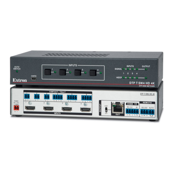
Page 13: Rear Panel Features
Powering on the Switcher on page 14). Configure the EDID Minder (optional, see EDID Minder on page 27). Power on the source devices. Rear Panel Features CONTACT/TALLY DTP T SW4 HD 4K REMOTE POWER OVER TP LINK HDBT RS-232 RS-232 AUTO 1.3 A MAX... - Page 14 RS-232 and IR control up to 330 feet (100 meters). The switcher and receiver can be powered by one 12 VDC power supply connected to the DTP T SW4 HD 4K switcher. The switcher cannot receive remote power in either mode.
-
Page 15: Wiring Connections
Over TP RS‑232 and IR control port (see figure 2 on page 5) — Connect a serial RS-232 signal, a modulated IR signal, or both into this 3.5 mm, 5-pole captive screw port for bidirectional RS-232 and IR communication (see Over TP RS‑232 and IR Connector on page 11). - Page 16 ATTENTION: • Always use a power supply supplied and or specified by Extron. Use of an unauthorized power supply voids all regulatory compliance certification and may cause damage to the supply and the end product. • Utilisez toujours une source d’alimentation fournie ou recommandée par Extron. L’utilisation d’une source d’alimentation non autorisée annule toute conformité...
-
Page 17: Contact Closure Connectors
Contact Closure Connectors Connect a push-button contact closure device to a Contact port (see figure 2, page 5) to enable input switching via contact closure. Wire and plug one of the provided 2-pole connectors into a Contact/Tally port representing the desired input number on the DTP T SW4 HD 4K CONTACT / TALLY (1, 2, or 3). -
Page 18: Tp Connector And Cable Recommendations
TP Connector and Cable Recommendations The TIA/EIA T 568B wiring standard is detailed in figure 4. Use this standard to terminate the TP cable with RJ-45 connectors. Side Pins: RJ-45 1 2 3 4 5 6 7 8 Connector TIA/EIA T 568B Wire color White-orange... -
Page 19: Over Tp Rs-232 And Ir Connector
Use a female 9-pin D connector to bare wire RS-232 cable or a universal control cable (UC50' or UC100') to connect your computer or control system to the 3-pole captive screw port (see figure 6 to wire the connector). RS-232 Device DTP T SW4 HD 4K Do not tin Transmit (Tx) the wires! Receive (Rx) Ground ( G ) Figure 6. -
Page 20: Auto-Input Switching
Auto-Input Switching The DTP T SW4 HD 4K switcher can automatically select the active, connected input based on detection of an active video signal (TMDS clock activity). If two or more inputs are active, the highest-numbered input port with an active signal is selected. When auto-input switching is in effect, the green Auto Switch LED on the front panel (see figure page 13) lights and the front panel input buttons are disabled. -
Page 21: Operation
Front Panel Features INPUTS INPUTS OUTPUT AUTO SIGNAL SWITCH CONFIG HDCP DTP T SW4 HD 4K DTP HDMI SWITCHER Auto Switch LED Inputs and Output Signal LEDs Config port HDCP status LEDs Input selection buttons and LEDs Figure 7. DTP T SW4 HD 4K Front Panel Auto Switch LED —... -
Page 22: Operations
Signal LEDs (see figure 7 on the previous page) — Inputs — Light when a source is connected to the corresponding input and TMDS • clock activity is detected. NOTE: If the source device connected to the selected input is HDCP encrypted (requires HDCP authentication), the corresponding signal LED may not light unless HDCP has been authenticated. -
Page 23: Contact/Tally Modes
Contact closure — Insert one of the provided 2-pole or 4-pole captive screw • connectors into the rear panel Contact port to enable input switching via contact closure on inputs 1 through 4. To make input selections via contact closure from the rear panel, Contact Closure pins (C) need to be momentarily shorted to the Ground pin (G) (see Contact Closure Connectors... -
Page 24: Contact/Tally Mode 0
• Contact ports are controlled externally, using Show Me cables or other button switches. • When a specific contact port is shorted (closed), the DTP T SW4 HD 4K switches to the associated video input. • Firmware controls the actions of the tally port. -
Page 25: Contact/Tally Mode 1
The Extron OCS 100C occupancy sensor is connected to contact port 6, which provides closure when it senses occupancy in the room. The DTP T SW4 HD 4K provides an unsolicited response to the Extron IPL Pro S1 • via RS-232 drivers. - Page 26 In the Contact/Tally Mode 1 diagram, the IPL Pro S3 controls all six ports, as it monitors the status of the ports through the RS-232 driver. The IPL also controls the display, sending the command to power it On and Off. Operation of Contact/Tally Mode 1: •...
-
Page 27: Contact/Tally Mode 2
Contact/Tally Mode 2 Ports Operations 1 through 4 • Contact ports are controlled externally, using Show Me cables or other button switches. When a specific contact port is shorted (closed), the DTP T SW4 HD 4K switches to the • associated video input. • Firmware controls the actions of the tally port. - Page 28 HDMI Show Me Cables Figure 10. The DTP T SW4 HD 4K PLUS in Contact/Tally Mode 2 In the Contact/Tally Mode 2 diagram, ports 1 through 4 are associated with inputs 1 through 4, so the video input can be selected using the Extron Show Me cables or the input buttons on the front panel.
- Page 29 • Contact ports are controlled externally, using Show Me cables or other button switches. • When a specific contact port is shorted (closed), the DTP T SW4 HD 4K switches to the associated video input. • Firmware controls the actions of the tally port.
- Page 30 In the Contact/Tally Mode 3 diagram, ports 1 through 4 are associated with inputs 1 through 4, so the video input can be selected using the Extron Show Me cables or the input buttons on the front panel. The IPL Pro S3 monitors the status of the CCR 2BLB through ports 5 and 6 to bring the volume up or down on the display.
-
Page 31: Control Processor Configuration For Contact/Tally Modes
Control Processor Configuration for Contact/Tally Modes When the DTP T SW4 HD 4K PLUS is connected to a Pro Series control processor to control and monitor peripheral devices, the control processor must be configured using Global Configurator Professional and Global Configurator Plus (GCP). -
Page 32: Resetting
Type A Ports USB Cable INPUTS INPUTS OUTPUT AUTO SIGNAL SWITCH CONFIG HDCP DTP T SW4 HD 4K DTP HDMI SWITCHER DTP T SW4 HD 4K Front Panel T SW4 HD 4K F Figure 14. USB Port Connection DTP T SW4 HD 4K • Operation... - Page 33 If this is the first time you have connected a DTP T SW4 HD 4K to this USB port on your computer, the opens. Found New Hardware Wizard On the first screen, indicate if it is necessary to connect to Windows Update to search the Web for the driver needed to communicate with the switcher via the USB port.
- Page 34 On the next screen, select the Install the software automatically radio button (see figure 11, below). (Recommended) Click ). You do not need to insert a disc. Next Figure 16. Select the Radio Button to Install the USB Driver Automatically Your computer locates the driver needed for it to communicate with the DTP T SW4 HD 4K via the USB port and loads it to the computer hard drive.
-
Page 35: Edid Minder
EDID Minder The DTP T SW4 HD 4K switcher uses EDID Minder, which ensures that a source device connected to the HDMI input continuously sees the EDID of a sink device, even after the sink is disconnected. By default, the EDID is set to 1080p @ 60 Hz with 2-channel audio (slot 11). Additional available values are shown in the table below. -
Page 36: Hdcp
HDCP The DTP T SW4 HD 4K switcher acts as an HDCP and HDMI repeater by actively handling HDCP key negotiation and authentication on the inputs and the output. However, it does not report itself as a repeater or forward a KSV list. The switcher supports HDCP output mode. Input The HDMI input negotiates and authenticates HDCP with the source device if the source requires HDCP encryption. -
Page 37: Product Configuration Software
Product Configuration Software The Extron Product Configuration Software is a Windows-based application that allows the user to configure and control the DTP SW4 HD 4K switcher. Topics include: • Downloading PCS Software Configuring the DTP T SW4 HD 4K with PCS • • Updating Firmware Using PCS Downloading PCS Software To begin, visit www.extron.com... -
Page 38: Configuring The Dtp T Sw4 Hd 4K With Pcs
Open the PCS software on the control PC from the PCS icon loaded on the desktop (optional, see image on the right) or from the menu. Start Click Start > Programs > Extron Electronics > Extron Product Configuration Software > Extron Product Configuration Software opens to the screen. Product Configuration Software Device Discovery Figure 19. -
Page 39: Input/Output Configuration Menu
Input/Output Configuration Menu This menu allows the user to configure the active inputs and output (see figure 20, the previous page). Input Configuration Panel panel allows the user to select an input and Input Configuration HDCP Authorized for the input. It also indicates which input is selected and the of an input. -
Page 40: Edid Minder Menu
figure (see on the previous page) indicates whether the DTP/HDBT Status receiver connected to the DTP/HDBT output is an Extron DTP receiver or an HDBase T enabled receiver. Select a radio button from the ) to set the switcher to either follow the HDCP Mode current input, or always encrypt the output. - Page 41 figure From the drop-down menu (see on the previous page) Resolution select a specific resolution or From the drop-down menu ( ) select a specific refresh rate or Refresh Rate From the drop-down menu ( ) select Video Format HDMI Assigning EDID To assign EDID to selected inputs: From the...
-
Page 42: General Settings Menu
General Settings Menu This menu is used to view the (see figure 24, ), configure the Hardware Settings ), and enable or disable Contact Closure and Tally Settings Front Panel Lockout (Exec Mode) Figure 24. General Settings Menu Hardware Settings Click the button ( Hardware Settings... -
Page 43: Av Controls Panel
• Click to allow the 1‑4 are input switching, 5 & 6 represent single switches firmware to control the actions of the input Contact/Tally on all inputs. Inputs 1 through 4 — When the Contact pin (C) is momentarily shorted, Contact and Tally follow that input. -
Page 44: Device Menu
Device Menu menu (see image on the right) allows the user to: Device the device from PCS. Disconnect View the hardware Settings to factory default. Reset Device (see Loading the Update Firmware Firmware to the Switcher on page 37). View information About this Module. -
Page 45: Updating Firmware Using Pcs
Updating Firmware Using PCS Updates to the DTP T SW4 HD 4K firmware are made available periodically via the Extron website. You can find out what version of firmware is currently loaded on your switcher by entering the SIS command via the RS-232 or USB interface (see Query firmware version on page 45) or listed in... - Page 46 Unless you Start specified otherwise in the installation of PCS, make the following selection from the menu: Start Start > All Programs > Extron Electronics > Extron Product Configuration Software > Extron Product Configuration Software The P opens to the screen...
- Page 47 Click Update Firmware to this Device... Figure 29. Update Firmware to this Device window opens. Update Firmware Figure 30. Update Firmware Window Click (see figure 30, Continue Click to navigate to the device-specific firmware file that has Open Firmware File... been downloaded on your PC.
-
Page 48: Remote Communication And Control
No response is required from the host. The switcher sends the following message when it is first powered on: (C) Copyright 2017, Extron Electronics DTP 4K, Vn.nn, 60‑1625‑01 is the firmware version number. • Vn.nn DTP T SW4 HD 4K • Remote Communication and Control... -
Page 49: Error Responses
Error Responses If the switcher is unable to execute a command it receives because the command is invalid or contains invalid parameters, the switcher returns an error response to the host. The following error response codes can be sent: – Invalid input channel (out of range) –... - Page 50 = Switch mode 0 = Manual 1 = Auto = Firmware version (to the second decimal place) = Output HDCP mode 0 = (default) Encrypt as required by input. Continuous trials for HDMI sinks Attempt for 10 seconds on DVI sinks, then fail 1 = Always encrypt Continuous trials for HDMI sinks Attempt for 10 seconds on DVI sinks, then fail...
-
Page 51: Command And Response Table For Sis Commands
Command and Response Table for SIS Commands ASCII Command Response Command Additional Description (Host to Switcher) (Switcher to Host) Input Selection Select input (audio and video) • All Select input = input number: 0 - 4 0 = deselect all inputs (disable output) Video Mute Video mute X1#]... - Page 52 ASCII Command Response Command Additional Description (Host to Switcher) (Switcher to Host) HDCP Input Authorization Enable or disable HDCP HDCP HdcpE Set HDCP authentication for input authentication per input . For 0 = Disable HDCP authentication 1 = Enable HDCP authentication (default) Enable or disable HDCP HDCP HdcpE...
- Page 53 ASCII Command Response Command Additional Description (Host to Switcher) (Switcher to Host) Behavior of Contact/Tally Ports Set mode E X1* X1(] : disable/enable, which selects 0 MUTM Mutm channel if current channel is re-selected. Query setting X1(] Show Contact/Tally port setting. MUTM Front Panel Lockout Enable or disable lock mode...
-
Page 54: Mounting
Mounting Mounting the DTP T SW4 HD 4K Switcher The DTP T SW4 HD 4K switcher can be set on a table, mounted on a rack shelf, or mounted under a desk, podium, or table. ATTENTION: • Installation and service must be performed by authorized personnel only. • L’installation et l’entretien doivent être effectués par le personnel autorisé... -
Page 55: Extron Warranty
Extron Electronics makes no further warranties either expressed or implied with respect to the product and its quality, performance, merchantability, or fitness for any particular use. In no event will Extron Electronics be liable for direct, indirect, or consequential damages resulting from any defect in this product even if Extron Electronics has been advised of such damage.
Need help?
Do you have a question about the DTP T SW4 HD 4K and is the answer not in the manual?
Questions and answers