Table of Contents
Advertisement
Quick Links
Advertisement
Table of Contents

Related Manuals for ICP DAS USA iDCS-8000


Summary of Contents for ICP DAS USA iDCS-8000
- Page 1 Remote Rugged I/O System with Redundancy Hardware User's Manual...
- Page 3 Revision History Revision Date Description of Change 1.43 2013/08/14 Adding pulse input module to this user’s hardware manual 1.42 2013/06/28 Adding analog module to this hardware user’s manual 1.41 2013/06/03 Adding some description for the section of mounting. 1.40 2013/05/22 Document release...
- Page 4 Preface Warranty All products manufactured by ICP DAS are under warranty regarding defective materials for a period of one year from the date of delivery to the original purchaser. Warning ICP DAS assumes no liability for damages resulting from the use of this product. ICP DAS reserves the right to change this manual at any time without notice.
-
Page 5: Table Of Contents
SECTION 4 I/O MODULE ..........................33 4.1 I ............................33 NTRODUCTION 4.1.1 LED status ............................33 4.1.2 D-Sub 37 pin connector......................33 4.1.3 Timing Characteristics ....................... 34 4.2 D ............................35 IGITAL NPUT 4.2.1 F-8040 .............................. 35 iDCS-8000 Hardware User Manual (2013/8/14, Rev: 1.43) - Page 6 5.3.1 DN-AIO-M ............................79 5.3.2 DN-RTD-M ............................. 81 5.3.3 DN-TC-M ............................83 5.3.4 DN-AIH-08 ............................. 85 5.4 A ............................87 NALOG UTPUT 5.4.1 DN-AIO-M ............................87 5.5 P .............................. 89 ULSE NPUT 5.5.1 DN-PI-M ............................89 iDCS-8000 Hardware User Manual (2013/8/14, Rev: 1.43)
-
Page 7: Section 1 Introduction
I/O modules and process cabling. It is highly modularized and flexible, so that I/O modules can be combined to suit many applications. The iDCS-8000 can be mounted in many configurations to fit most requirements, both in single or fully redundant applications. -
Page 8: Feature
The iDCS-8000 is an open comprehensive, distributed, process I/O system. It communicates with controller over industry-standard field buses. It brings benefit for users install to iDCS-8000 in the field, to close to sensors and actuators, to reduce the installation cost by reducing the cost of cabling. -
Page 9: Hardware Structure
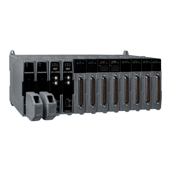
Hardware Structure Section 1 Introduction 1.3 Hardware Structure The iDCS-8000 is made by the combination of components of the backplane, power modules, communication modules, I/O modules and an termination board. Backplane Power Communication Backplane The backplane consists of 2 slots of power, 2 slots of communication and 8 single or 4 pairs of redundant I/O modules. -
Page 10: Hardware List
Section 1 Introduction Hardware List 1.4 Hardware List The equipment that is used as part of the iDCS-8000 station is presented in the following table. Type Module Name Description Communication Module FCM-MTCP Modbus/TCP Communication Module Power Module FPM-D2440 24VDC Input,35W@5VDC Output... -
Page 11: Installation
Installation Section 1 Introduction 1.5 Installation 1.5.1 Environment Specification The following table is the absolute maximum rating of the environmental specification for the iDCS-8000. Parameter Specification Operating Temperature -25℃~75℃ Operating Humidity 5 ~ 95 % RH, non-condensing Storage Temperature -40℃~85℃... - Page 12 Section 1 Introduction Installation 1.5.2.2 iDCS-8000 Body (Module Plugged) Units: mm iDCS-8000 Hardware User Manual (2013/8/14, Rev: 1.43)
- Page 13 Installation Section 1 Introduction 1.5.2.3 FRMK (Wall mount panel) iDCS-8000 Hardware User Manual (2013/8/14, Rev: 1.43)
- Page 14 Section 1 Introduction Installation 1.5.2.4 Termination Board DN-DO-16DR-A / DN-DO-16DR-B / DN-DI-32DW iDCS-8000 Hardware User Manual (2013/8/14, Rev: 1.43)
- Page 15 Installation Section 1 Introduction DN-DIO-M / DN-AIO-M / DN-TC-M / DN-RTD-M iDCS-8000 Hardware User Manual (2013/8/14, Rev: 1.43)
- Page 16 Section 1 Introduction Installation DN-AIH-04 iDCS-8000 Hardware User Manual (2013/8/14, Rev: 1.43)
-
Page 17: Mounting
Section 1 Introduction 1.5.3 Mounting There are 3 types of mounting, the DIN-rail, panel and wall, for iDCS-8000 to install in your cabinet or other places. The iDCS-8000 is originally designed for DIN-rail and wall mounting by the mechanism. The following section will describe how to mount the iDCS-8000 in different type. - Page 18 Section 1 Introduction Installation Successful mounting iDCS-8000 1.5.3.2 Panel mounting Use screw drive to mount the iDCS-8000 to the FRMK with M4 screw iDCS-8000 Hardware User Manual (2013/8/14, Rev: 1.43)
- Page 19 The steps of wall mounting are same as panel mounting. The difference between panel and wall mounting is the FRMK unit. The 4 M4 screws directly screwed iDCS-8000 unit to the plane you want. iDCS-8000 Hardware User Manual (2013/8/14, Rev: 1.43)
-
Page 20: Module Installation
Section 1 Introduction Installation 1.5.4 Module Installation Installing along the guiding rail then pushing into 48-pin socket Guiding rail Lock the module Locker Push following this direction to lock the module iDCS-8000 Hardware User Manual (2013/8/14, Rev: 1.43) -
Page 21: Wiring
Installation Section 1 Introduction 1.5.5 Wiring Single Operation Redundant Operation iDCS-8000 Hardware User Manual (2013/8/14, Rev: 1.43) -
Page 22: Field Grounding
There are many ways to ground iDCS-8000 to earth ground. The most common way to ground to earth is by using the sheet metal behind the iDCS-8000. When mount the iDCS-8000 with DIN-rail in cabinet, the sheet metal will attach to the conductor of the cabinet to lead to ground. - Page 23 In order to prevent the operators to get an electric shock and external noise to affect iDCS-8000 system, the cabinet of the iDCS-8000 must set earthed. And all the metal that the operators might touch must set earthed. The grounded system must follow “Electrical Equipment Technical Standard” Class D specification and the earth resistance must be below 100Ω.
- Page 24 Section 1 Introduction Installation iDCS-8000 Hardware User Manual (2013/8/14, Rev: 1.43)
-
Page 25: Terminals And Wiring
Section 1 Introduction 1.5.7 Terminals and Wiring The termination board of the iDCS-8000 is a bridge between field devices and I/O modules. The termination board provides a pluggable terminal block to connect field devices to termination board. Users can easily replace the termination board by removing the pluggable terminal block . -
Page 26: Cable
80℃ 37P D-Sub Male Cable CA-02 Semi-rigidPVC 80℃ 37P D-Sub Male Cable CA-03 Semi-rigidPVC 80℃ 37P D-Sub Male Cable CA-05 Semi-rigidPVC 80℃ 37P D-Sub Male Cable CA-10 Semi-rigidPVC 80℃ 37P D-Sub Male Cable iDCS-8000 Hardware User Manual (2013/8/14, Rev: 1.43) -
Page 27: Section 2 Power Modules
24VDC input Diagnostic Redundancy The FPM-D2440 is a power module. It offers the isolated power source to the iDCS-8000 system. The FPM-D2440 can be used to single or redundant application. It also has diagnostic to make system more reliable. -
Page 28: Pin Assignment
2.1.3 Pin Assignment Description 24 VDC P.GND Ground Frame Ground 2.1.4 LED Indicator Status Description Normal operation No input or invalid input Output lower than 4.5V Module failure Output overloaded iDCS-8000 Hardware User Manual (2013/8/14, Rev: 1.43) -
Page 29: Internal Hardware Structure
1.3 W + 1.1 W 1. 24V is used for the power in passive loop. The power consumption depends on the number of sensors are connected. 2. The power consumption depends on the load. iDCS-8000 Hardware User Manual (2013/8/14, Rev: 1.43) -
Page 30: Section 3 Communication Module
(Auto negotiating, Auto MDIX) Protocol Modbus/TCP LED indicators 1 Power, 2 Fault, 1 Link/Active/Speed Power consumption Redundant Operating temperature -25°C ~ +75°C 3000V (Between LAN port and F.G) Isolation 1000V (Between LAN port and backplane) iDCS-8000 Hardware User Manual (2013/8/14, Rev: 1.43) -
Page 31: Switches
The other 3 addresses can be configured through MiniOS7 Utility. 3.1.4 LED Indicators Status On:Heavy fault Off:Normal On:Module Power On Off:Module Power Off On:Light fault Off:Normal On:Ethernet Link Establish Off:No Ethernet Link On:Ethernet Activity Off:No Ethernet Activity iDCS-8000 Hardware User Manual (2013/8/14, Rev: 1.43) -
Page 32: Ethernet Port
FCM-MTCP 3.1.5 Ethernet Port The iDCS-8000 is equipped with one Ethernet port which is fully compliant with IEEE 802.3u 10/100BASE-TX. The Ethernet port provides a standard RJ-45 with green color LED indicator on the front side showing activity (Off: No activity, Green and Flash: Activity), and orange color LED indicator showing link status (Off: No Link, Orange: Link established). -
Page 33: Section 4 I/O Module
4.1.2 D-Sub 37 pin connector The D-Sub 37 pin connector is the interface to field devices. Every module has individual pin assignment for wiring. The termination boards are wiring boards used for easily wiring and maintenance purpose. iDCS-8000 Hardware User Manual (2013/8/14, Rev: 1.43) -
Page 34: Timing Characteristics
Response time for analog input high/low alarm <32 ms (16 channels) <1.2 s Response time for TC/RTD high/low alarm <100 ms Time when detect CJC broken <1.2 s Time when detect TC/RTD channel broken iDCS-8000 Hardware User Manual (2013/8/14, Rev: 1.43) -
Page 35: Digital Input
32 (One COM for all channels) Type Wet, current sinking / sourcing Rated voltage 36 V Input voltage range, “1” 18 V ~30 V Input voltage range, “0” 11 V Detection time 100us Input impedance 5.2KΩ, 0.25W iDCS-8000 Hardware User Manual (2013/8/14, Rev: 1.43) - Page 36 Maximum power consumption 1.8 W Operating temperature -25℃ ~ +75℃ Humidity 5 ~ 95 % RH, Non-condensing Weight 300 g Dimensions (W x L x H) 30mm x 85mm x 115mm 4.2.1.3 Hardware Structure iDCS-8000 Hardware User Manual (2013/8/14, Rev: 1.43)
- Page 37 Digital Input Section 4 I/O Module 4.2.1.4 Pin Assignment iDCS-8000 Hardware User Manual (2013/8/14, Rev: 1.43)
-
Page 38: Digital Output
32 as channel 0~31 status Digital Output Number of channels 32 (NPN) Type Current sinking, Open-collector Rated voltage 36 V Output load current, maximum 0.5 A Output switching time 100 us Output impedance 2 Ω Isolation 3000V iDCS-8000 Hardware User Manual (2013/8/14, Rev: 1.43) - Page 39 Maximum power consumption 2.3 W Operating temperature -25℃ ~ +75℃ Humidity 5 ~ 95 % RH, Non-condensing Weight 300 g Dimensions (W x L x H) 30mm x 85mm x 115mm 4.3.1.3 Hardware Structure iDCS-8000 Hardware User Manual (2013/8/14, Rev: 1.43)
- Page 40 Section 4 I/O Module Digital Output 4.3.1.4 Pin assignments iDCS-8000 Hardware User Manual (2013/8/14, Rev: 1.43)
-
Page 41: Analog Input
This module has ±0.05% accuracy for highly accurate application. Besides, the F-8015 provides 3000V optical isolation between channels and backplane bus. If any high voltage or current damages these channels, this module won’t affect other component in iDCS-8000 system. 4.4.1.2 Specification Parameter... - Page 42 DN-RTD-M Maximum power consumption Operating temperature -25℃ ~ +75℃ Humidity 5 ~ 95 % RH, Non-condensing Weight 300 g Dimensions (W x L x H) 30mm x 85mm x 115mm 4.4.1.3 Hardware Structure iDCS-8000 Hardware User Manual (2013/8/14, Rev: 1.43)
- Page 43 Analog Input Section 4 I/O Module 4.4.1.4 Pin assignments iDCS-8000 Hardware User Manual (2013/8/14, Rev: 1.43)
-
Page 44: F-8017C1
Maximum Allowable Input Current 25mA Resolution 16 bit Sampling Rate 500 Samples/sec (Total) Accuracy ±0.05% FSR Zero Drift ±20 μV/℃ Span Drift ±25 ppm/℃ Common Mode Rejection 86 dB Normal Mode Rejection 100 dB iDCS-8000 Hardware User Manual (2013/8/14, Rev: 1.43) - Page 45 Maximum power consumption 1.5 W Operating temperature -25℃ ~ +75℃ Humidity 5 ~ 95 % RH, Non-condensing Weight 300 g Dimensions (W x L x H) 30mm x 85mm x 115mm 4.4.2.3 Hardware Structure iDCS-8000 Hardware User Manual (2013/8/14, Rev: 1.43)
- Page 46 Section 4 I/O Module Analog Input 4.4.2.4 Pin assignments iDCS-8000 Hardware User Manual (2013/8/14, Rev: 1.43)
-
Page 47: F-8017C2
0.05% accuracy for highly accurate application. Moreover, this module is built-in 2 ADC to provide same sampling rate as F-8017C1 for some application. The F-8017C2 provides 3000VDC optical isolation between channels and backplane bus. If any high voltage or current damages these channels, this module won’t affect other component in iDCS-8000 system. 4.4.3.2 Specification Parameter... - Page 48 Maximum power consumption 2.2 W Operating temperature -25℃ ~ +75℃ Humidity 5 ~ 95 % RH, Non-condensing Weight 300 g Dimensions (W x L x H) 30mm x 85mm x 115mm 4.4.3.3 Hardware Structure iDCS-8000 Hardware User Manual (2013/8/14, Rev: 1.43)
- Page 49 Analog Input Section 4 I/O Module 4.4.3.4 Pin assignments iDCS-8000 Hardware User Manual (2013/8/14, Rev: 1.43)
-
Page 50: F-8017Ch
Number of channels Type 4~20 mA (Support ±25% overrange) Maximum Allowable Input Current 25mA Resolution 16 bit Sampling Rate 500 Samples/sec (Total) Accuracy ±0.05% FSR Zero Drift ±20 μV/℃ Span Drift ±25 ppm/℃ iDCS-8000 Hardware User Manual (2013/8/14, Rev: 1.43) - Page 51 1. F-8017CH provides the power for the passive loop, so there will be an extra power for the transmitter in the field. The amount of power consumption depends on the number of transmitters. 4.4.4.3 Hardware Structure iDCS-8000 Hardware User Manual (2013/8/14, Rev: 1.43)
- Page 52 Section 4 I/O Module Analog Input 4.4.4.4 Pin assignments iDCS-8000 Hardware User Manual (2013/8/14, Rev: 1.43)
-
Page 53: F-8019
±500mV, ±1V, ±2.5V, ±5V, ±10V, Type J, K, T, E, R, S, B, N, C -210 ~ +1200 ℃ -270 ~ +1372 ℃ Temperature Range -270 ~ +400 ℃ -270 ~ +1000 ℃ iDCS-8000 Hardware User Manual (2013/8/14, Rev: 1.43) - Page 54 Termination board DN-TC-M Maximum power consumption 1.3 W Operating temperature -25℃ ~ +75℃ Humidity 5 ~ 95 % RH, Non-condensing Weight 300 g Dimensions (W x L x H) 30mm x 85mm x 115mm iDCS-8000 Hardware User Manual (2013/8/14, Rev: 1.43)
- Page 55 Analog Input Section 4 I/O Module 4.4.5.3 Hardware Structure 4.4.5.4 Pin assignments iDCS-8000 Hardware User Manual (2013/8/14, Rev: 1.43)
-
Page 56: Analog Output
Moreover, this module has ±0.05% accuracy for highly accurate application. Besides, the F-8028CV provides 3000V optical isolation between channels and backplane bus. If any high voltage or current damages these channels, this module won’t affect other component in iDCS-8000 system. 4.5.1.2 Specification Parameter... - Page 57 Operating temperature -25℃ ~ +75℃ Humidity 5 ~ 95 % RH, Non-condensing Weight 300 g Dimensions (W x L x H) 30mm x 85mm x 115mm 1. The power consumption depends on the load. iDCS-8000 Hardware User Manual (2013/8/14, Rev: 1.43)
- Page 58 Section 4 I/O Module Analog Output 4.5.1.3 Hardware Structure 4.5.1.4 Pin assignments NOTE: The voltage output will start from channel 8. iDCS-8000 Hardware User Manual (2013/8/14, Rev: 1.43)
-
Page 59: F-8028Ch
1 RUN, 1 ACT, 1 DUX Analog Output Number of channels Type 4 ~ 20 mA, currnet sourcing Maximum Allowable Output Range ±25% (0 ~ 24 mA) Resolution 16 bit Output Response Time <200 μS Accuracy ±0.05% FSR iDCS-8000 Hardware User Manual (2013/8/14, Rev: 1.43) - Page 60 -25℃ ~ +75℃ Humidity 5 ~ 95 % RH, Non-condensing Weight 300 g Dimensions (W x L x H) 30mm x 85mm x 115mm 1. The power consumption depends on the load. 4.5.2.3 Hardware Structure iDCS-8000 Hardware User Manual (2013/8/14, Rev: 1.43)
- Page 61 Analog Output Section 4 I/O Module 4.5.2.4 Pin assignments iDCS-8000 Hardware User Manual (2013/8/14, Rev: 1.43)
-
Page 62: Pulse Input
Min. Pulse Width 2 us Input Frequency Range 1 Hz ~ 500 KHz Rated Voltage 30 V Input voltage range, “1” 4.5 V ~ 30 V Input voltage range, “0” < 1 V iDCS-8000 Hardware User Manual (2013/8/14, Rev: 1.43) - Page 63 Maximum power consumption 1.9 W Operating temperature -25℃ ~ +75℃ Humidity 5 ~ 95 % RH, Non-condensing Weight 300 g Dimensions (W x L x H) 30mm x 85mm x 115mm 4.6.1.3 Hardware Structure iDCS-8000 Hardware User Manual (2013/8/14, Rev: 1.43)
- Page 64 Section 4 I/O Module Pulse Input 4.6.1.4 Pin assignments iDCS-8000 Hardware User Manual (2013/8/14, Rev: 1.43)
-
Page 65: Section 5 Termination Board
Wet contact (Current sinking/sourcing) Channel General Dimension (W x L x H) 112 x 117 x 29 mm Mounting 35 mm DIN Rail, Wall Operating temperature -25 ~ 75℃ Humidity 5 ~ 95 % RH, Non-condensing iDCS-8000 Hardware User Manual (2013/8/14, Rev: 1.43) - Page 66 DI16 DI17 DI18 DI19 DI20 DI21 DI22 DI23 DI24 DI25 DI26 DI27 DI28 DI29 DI30 DI31 N/A COM DI9 DI10 DI11 DI12 DI13 DI14 DI15 N/A COM 5.1.1.4 Wiring Wet contact (Current sinking / sourcing) iDCS-8000 Hardware User Manual (2013/8/14, Rev: 1.43)
-
Page 67: Dn-Di-32Dw
Dimension (W x L x H) 126.6 x 274.6 x 25.5 mm Mounting 35 mm DIN Rail, Wall Operating temperature -25 ~ 75℃ Humidity 5 ~ 95 % RH, Non-condensing Wet/Dry contact is Jumper selectable iDCS-8000 Hardware User Manual (2013/8/14, Rev: 1.43) - Page 68 Section 5 Termination Board Digital Input 5.1.2.3 Hardware structure F-8040 with DN-DI-32DW (Dry contact – Current sourcing) F-8040 with DN-DI-32DW (Dry contact – Current sinking) iDCS-8000 Hardware User Manual (2013/8/14, Rev: 1.43)
- Page 69 Wet Contact Dry Contact Dry Contact Current Sinking / Sourcing Current Sinking Current Sourcing NOTE: Please make sure the external power is attached as well when use dry contact wire connection. iDCS-8000 Hardware User Manual (2013/8/14, Rev: 1.43)
- Page 70 DI16 DI17 DI18 DI19 DI20 DI21 DI22 DI23 DI24 DI25 DI26 DI27 DI28 DI29 DI30 DI31 NC NC COM COM COM COM COM COM COM COM COM COM COM COM COM COM COM COM NC iDCS-8000 Hardware User Manual (2013/8/14, Rev: 1.43)
- Page 71 Digital Input Section 5 Termination Board 5.1.2.6 Wiring Dry contact (Current sourcing) Dry contact (Current sinking) iDCS-8000 Hardware User Manual (2013/8/14, Rev: 1.43)
- Page 72 Section 5 Termination Board Digital Input Wet contact (Current sinking / sourcing) iDCS-8000 Hardware User Manual (2013/8/14, Rev: 1.43)
-
Page 73: Digital Output
Current sinking, Open-collector Channel General Dimension (W x L x H) 112 x 117 x 29 mm Mounting 35 mm DIN Rail, Wall Operating temperature -25 ~ 75℃ Humidity 5 ~ 95 % RH, Non-condensing iDCS-8000 Hardware User Manual (2013/8/14, Rev: 1.43) - Page 74 DO16 DO17 DO18 DO19 DO20 DO21 DO22 DO23 DO24 DO25 DO26 DO27 DO28 DO29 DO30 DO31 GND PWR DO0 DO1 DO2 DO3 DO4 DO5 DO6 DO7 DO8 DO9 DO10 DO11 DO12 DO13 DO14 DO15 GND PWR 5.2.1.4 Wiring iDCS-8000 Hardware User Manual (2013/8/14, Rev: 1.43)
-
Page 75: Dn-Do-16Dr-A & Dn-Do-16Dr-B
Form C relay, it can be positive (N.O.) or negative (N.C.) logic output or both. In addition, each channel is built-in two varistors on N.O. and N.C. channel to protect against high-voltage transients and surges to the control loop. iDCS-8000 Hardware User Manual (2013/8/14, Rev: 1.43) - Page 76 Rated voltage 470Vrms General Dimension (W x L x H) 126.6 x 274.6 x 25.5 mm Mounting 35 mm DIN Rail, Wall Ambient Temperature -25 ~ 75℃ Humidity 5 ~ 95 % RH, Non-condensing iDCS-8000 Hardware User Manual (2013/8/14, Rev: 1.43)
- Page 77 5.2.2.4 Pin Assignment DN-DO-16DR-A COM0 COM1 COM2 COM3 COM4 COM5 COM6 COM7 COM8 COM9 NO10 NC10 COM10 NO11 NC11 COM11 NO12 NC12 COM12 NO13 NC13 COM13 NO14 NC14 COM14 NO15 NC15 COM15 iDCS-8000 Hardware User Manual (2013/8/14, Rev: 1.43)
- Page 78 COM21 NO22 NC22 COM22 NO23 NC23 COM23 CON2 NO24 NC24 COM24 NO25 NC25 COM25 NO26 NC26 COM26 NO27 NC27 COM27 NO28 NC28 COM28 NO29 NC29 COM29 NO30 NC30 COM30 NO31 NC31 COM31 5.2.2.5 Wiring iDCS-8000 Hardware User Manual (2013/8/14, Rev: 1.43)
-
Page 79: Analog Input
Analog Input Channel General Dimension (W x L x H) 112 x 117 x 29 mm Mounting 35 mm DIN Rail, Wall Operating temperature -25 ~ 75℃ Humidity 5 ~ 95 % RH, Non-condensing iDCS-8000 Hardware User Manual (2013/8/14, Rev: 1.43) - Page 80 CH8+ CH8- CH9+ CH9- CH10+ CH10- CH11+ CH11- CH12+ CH12- CH13+ CH13- CH14+ CH14- CH15+ CH15- CH0+ CH0- CH1+ CH1- CH2+ CH2- CH3+ CH3- CH4+ CH4- CH5+ CH5- CH6+ CH6- CH7+ CH7- 5.3.1.4 Wiring iDCS-8000 Hardware User Manual (2013/8/14, Rev: 1.43)
-
Page 81: Dn-Rtd-M
RTD Input Channel General Dimension (W x L x H) 112 x 117 x 29 mm Mounting 35 mm DIN Rail, Wall Operating temperature -25 ~ 75℃ Humidity 5 ~ 95 % RH, Non-condensing iDCS-8000 Hardware User Manual (2013/8/14, Rev: 1.43) - Page 82 Section 5 Termination Board Analog Input 5.3.2.3 Pin assignment 5.3.2.4 Wiring iDCS-8000 Hardware User Manual (2013/8/14, Rev: 1.43)
-
Page 83: Dn-Tc-M
Thermocouple Input Channel General Dimension (W x L x H) 112 x 117 x 29 mm Mounting 35 mm DIN Rail, Wall Operating temperature -25 ~ 75℃ Humidity 5 ~ 95 % RH, Non-condensing iDCS-8000 Hardware User Manual (2013/8/14, Rev: 1.43) - Page 84 Section 5 Termination Board Analog Input 5.3.3.3 Pin assignment CON1 NC CH0+ CH0- CH1+ CH1 CH2+ CH2- CH3+ CH3- CH4+ CH4- CH5+ CH5- CH6+ CH6- CH7+ CH7- 5.3.3.4 Wiring iDCS-8000 Hardware User Manual (2013/8/14, Rev: 1.43)
-
Page 85: Dn-Aih-08
320mA removeable and physical indicator fuse General Dimension (W x L x H) 135 x 214.6 x 25.5 mm Mounting 35 mm DIN Rail, Wall Operating temperature -25 ~ 75℃ Humidity 5 ~ 95 % RH, Non-condensing iDCS-8000 Hardware User Manual (2013/8/14, Rev: 1.43) - Page 86 NC CH0+ CH0- PWR0 GND0 CH1+ CH1- PWR1 GND1 CH2+ CH2- PWR2 GND2 CH3+ CH3- PWR3 GND3 CON1 NC CH4+ CH4- PWR4 GND4 CH5+ CH5- PWR5 GND5 CH6+ CH6- PWR6 GND6 CH7+ CH7- PWR7 GND7 5.3.4.4 Wiring iDCS-8000 Hardware User Manual (2013/8/14, Rev: 1.43)
-
Page 87: Analog Output
Analog Output Channel General Dimension (W x L x H) 112 x 117 x 29 mm Mounting 35 mm DIN Rail, Wall Operating temperature -25 ~ 75℃ Humidity 5 ~ 95 % RH, Non-condensing iDCS-8000 Hardware User Manual (2013/8/14, Rev: 1.43) - Page 88 CH8+ CH8- CH9+ CH9- CH10+ CH10- CH11+ CH11- CH12+ CH12- CH13+ CH13- CH14+ CH14- CH15+ CH15- CH0+ CH0- CH1+ CH1- CH2+ CH2- CH3+ CH3- CH4+ CH4- CH5+ CH5- CH6+ CH6- CH7+ CH7- 5.4.1.4 Wiring iDCS-8000 Hardware User Manual (2013/8/14, Rev: 1.43)
-
Page 89: Pulse Input
NC CH4+ CH4- PWR NC CH5+ CH5- PWR NC CH6+ CH6- PWR NC CH7+ CH7- PWR NC NC CH0+ CH0- PWR NC CH1+ CH1- PWR NC CH2+ CH2- PWR NC CH3+ CH3- PWR NC iDCS-8000 Hardware User Manual (2013/8/14, Rev: 1.43) - Page 90 Section 5 Termination Board Pulse Input 5.5.1.4 Wiring iDCS-8000 Hardware User Manual (2013/8/14, Rev: 1.43)
Need help?
Do you have a question about the iDCS-8000 and is the answer not in the manual?
Questions and answers