
Related Manuals for Tektronix 013-0278-XX


Summary of Contents for Tektronix 013-0278-XX
- Page 1 Instructions 013-0278-XX Video Display Clamp 070-8762-01 www.tektronix.com *P070876201* 070876201...
- Page 2 Copyright © Tektronix. All rights reserved. Licensed software products are owned by Tektronix or its subsidiaries or suppliers, and are protected by national copyright laws and international treaty provisions. Tektronix products are covered by U.S. and foreign patents, issued and pending. Information in this publication supercedes that in all previously published material.
- Page 3 Tektronix, with shipping charges prepaid. Tektronix shall pay for the return of the product to Customer if the shipment is to a location within the country in which the Tektronix service center is located. Customer shall be responsible for paying all shipping charges, duties, taxes, and any other charges for products returned to any other locations.
-
Page 5: Table Of Contents
........013-0278-XX Video Display Clamp... - Page 6 Table 7: Test Equipment ........013-0278-XX Video Display Clamp...
-
Page 7: General Safety Summary
Avoid Exposed Circuitry. Do not touch exposed connections and components when power is present. Do Not Operate in Wet/Damp Conditions. Do Not Operate in an Explosive Atmosphere. Keep Product Surfaces Clean and Dry. 013-0278-XX Video Display Clamp... - Page 8 H WARNING indicates an injury hazard not immediately accessible as you read the marking. H CAUTION indicates a hazard to property including the product. The following symbol(s) may appear on the product: CAUTION Refer to Manual 013-0278-XX Video Display Clamp...
-
Page 9: Environmental Considerations
Support/Service section of the Tektronix Web site (www.tektronix.com). Restriction of Hazardous This product has been classified as Monitoring and Control equipment, and is Substances outside the scope of the 2002/95/EC RoHS Directive. 013-0278-XX Video Display Clamp... - Page 10 Environmental Considerations 013-0278-XX Video Display Clamp...
-
Page 11: The Video Display Clamp
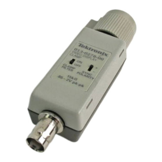
The Video Display Clamp Product Description The Tektronix 013-0278-00 Video Display Clamp is an active signal processor designed to increase your ability to monitor video signals. Figure 1: The video display clamp Video signals containing a 60 Hz ripple or a DC offset make it difficult to view the video signal with an oscilloscope. -
Page 12: Features
The Video Display Clamp receives its power from the host instrument. The host instrument must have a TEKPROBE Level 2 interface (such as the Tektronix TDS400, TDS500, and TDS600 Series Oscilloscopes). The video display clamp works with most popular signal formats including the... -
Page 13: Figure 3: Viewing A Video Signal Directly With The Video Display Clamp
The Video Display Clamp the signal, it makes it nearly impossible to obtain a viewable display of the video information. Use the Video Display Clamp to reduce or eliminate this type of interference to view the video signal. Viewing the video signals can be accomplished with several methods. H Connect a video signal directly to the video display clamp (see Figure 3). -
Page 14: Figure 5: Probing Circuits With The Video Display Clamp
The Video Display Clamp Video display clamp Figure 5: Probing circuits with the video display clamp Procedure Use the following short procedure to install and use the Video Display Clamp. Attaching the video display clamp to an oscilloscope with a TEKPROBE Level 2 interface automatically turns on the video display clamp. -
Page 15: Specifications
The Video Display Clamp Specifications The electrical characteristics found in these tables of warranted characteristics apply when operating at an ambient temperature between 0 _C and +50 _C. Table 1: Warranted Characteristics — Signal Pass Through (Insertion Characteristics) Name Description Bandwidth - - 3 dB at 70 MHz (100 MHz typical), ±1 dB out to 30 MHz (60 MHz The bandwidth of the video clamp signal path with the... -
Page 16: Table 4: Warranted Characteristics - Environmental
The Video Display Clamp Table 3: Warranted Characteristics — Video Display Clamp (Cont.) Name Description Crosstalk The maximum crosstalk interference created on the back 10 mV porch. Line Rates/Standards The video display clamp works with any bi-level sync 525/59.94/2:1 1050/59.94/2:1 pulse standard that has a back porch at least 3 s long. -
Page 17: Performance Verification
Level 2 interface, Tektronix TDS460 Signal display 100 MHz bandwidth 50 Ω, 36 in, male to male BNC connec- Cable, Precision Coaxial Tektronix part number Signal interconnection tors 012-0482-00 Termination, 50 Ω Impedance 50 Ω; connectors: female Tektronix part number... -
Page 18: Procedures
Item Number and Description Minimum Requirements Example Purpose Generator, Leveled Sine 60 Hz; Variable amplitude from 5 mV to TEKTRONIX SG502 Lev- 60 Hz rejection check into 50 Ω Wave eled Sine Wave Genera- Generator, Pulse 0 to 3 V, 15 kHz pulses with independent... -
Page 19: Figure 6: Back Porch Test Setup
Performance Verification Pulse Generator Video display clamp Dual-input coupler 50 Ω terminator 2.5X attenuator Coaxial cable Figure 6: Back porch test setup 3. Set the pulse generator as follows (viewed with channel 2): H Set the compliment to - - H Adjust the period to 15 kHz H Adjust the pulse duration to 5 s H Set the high level to 1.0 volts... -
Page 20: Figure 7: Back Porch Correction Check (Negative)
Performance Verification Test signal (channel 2) Corrected signal (channel 1) Figure 7: Back porch correction check (negative) 7. Set the test oscilloscope to display channel 2 (channel 1 off). 8. Set the pulse generator as follows: H Set the high level to - -0.8 volts H Set the low level to - -1.0 volts H Set the compliment to + 9. -
Page 21: Gain Error Check
Performance Verification Test signal (channel 2) Corrected signal (channel 1) Figure 8: Back porch correction test (positive) Gain Error Check These procedures check those characteristics that relate to the gain error of the Video Display Clamp listed as checked under Warranted Characteristics in the Specifications section. -
Page 22: Figure 9: Gain Error Test Setup
Performance Verification Pulse Generator Video display clamp Dual-input coupler 50 Ω terminator 2.5X attenuator Coaxial cable Figure 9: Gain error test setup 3. Set the pulse generator as follows: H Set the compliment to - - H Adjust the period to 15 kHz H Adjust the pulse duration to 5 s H Set the high level to 500 mV H Set the low level to - -500 mV... -
Page 23: Crosstalk And Timing Checks
Performance Verification Test signal (channel 2) Corrected signal (channel 1) Figure 10: Gain check Crosstalk and Timing These procedures check those characteristics that relate to crosstalk interference Checks and timing of the Video Display Clamp listed as checked under Warranted Characteristics in the Specifications section. -
Page 24: Figure 11: Crosstalk Test Setup
Performance Verification Pulse Generator Video display clamp Dual-input coupler 50 Ω terminator 2.5X attenuator Coaxial Cable Figure 11: Crosstalk test setup 3. Set the pulse generator as follows: H Set the compliment to - - H Adjust the period to 15 kHz H Adjust the pulse duration to 5 s H Set the high level to 0 V H Set the low level to - -300 mV... -
Page 25: Figure 12: Measuring Interference
Performance Verification Test signal (channel 2) Corrected signal (channel 1) Figure 12: Measuring interference 7. Switch the Video Display Clamp Polarity to + (positive) then back to - - (negative). 8. Verify that the pulse display returns to its original position within ±1 mV. 9. -
Page 26: Bandwidth Check
Performance Verification Bandwidth Check These procedures check those characteristics that relate to the bandwidth of the Video Display Clamp listed as checked under Warranted Characteristics in the Specifications section. Equipment Required: One sinewave generator (Item 6), one precision coaxial cable (Item 2), one 50 Ω terminator (Item 3), and one dual-input coupler (Item 5). -
Page 27: 60 Hz Rejection Check
Performance Verification 4. Set the Video Display Clamp as follows: H Polarity to - - (negative) H Filter to Off 5. Set the test oscilloscope to display channel 1 (channel 2 off). 6. Verify that the signal display amplitude is greater than 892 mV 60 Hz Rejection Check These procedures check those characteristics that relate to the 60 Hz rejection capability of the Video Display Clamp listed as checked under Warranted... -
Page 28: Figure 15: 60 Hz Rejection Test Setup
Performance Verification Sinewave Pulse Generator Generator Video display clamp 2.5X attenuator Dual-input Coaxial cable coupler Dual-input coupler Figure 15: 60 Hz rejection test setup 3. Set the Video Display Clamp as follows: H Polarity to - - (negative) H Filter to Off 4. -
Page 29: Figure 16: 60 Hz Rejection Check (Negative)
Performance Verification Test signal (channel 2) Corrected signal (channel 1) Figure 16: 60 Hz rejection check (negative) 10. Set the compliment of the pulse generator to +. 11. Set the Video Display Clamp Polarity to + (positive). 12. Verify that the amplitude of the 60 Hz sinewave component of the waveform is ≤70 mV (see Figure 17). - Page 30 Performance Verification 013-0278-00 Video Display Clamp...
-
Page 31: Maintenance
If the contact pins become damaged, obtain replacement pins through your Pins nearest Tektronix Field Office or representative. Use the following procedure to replace a damaged contact pin. 1. Using a pair of needle-nosed pliers, grasp the damaged pin and pull the pin straight out of the assembly (see Figure 18). - Page 32 Maintenance 013-0278-00 Video Display Clamp...
Need help?
Do you have a question about the 013-0278-XX and is the answer not in the manual?
Questions and answers