Table of Contents
Advertisement
Quick Links
A l l t e s t I n s t r u me n t s , I n c .
5 0 0 C e n t r a l A v e .
F a r mi n g d a l e , N J 0 7 7 2 7
P : ( 7 3 2 ) 9 1 9 - 3 3 3 9
F : ( 7 3 2 ) 9 1 9 - 3 3 3 2
a l l t e s t . n e t
s s a l e s @ a l l t e s t . n e t
T h e t e s t & me a s u r e me n t
e q u i p me n t y o u n e e d a t
t h e p r i c e y o u w a n t .
A l l t e s t c a r r i e s t h e w o r l d ' s l a r g e s t s e l e c t i o n o f
u s e d / r e f u r b i s h e d b e n c h t o p t e s t & me a s u r e me n t
e q u i p me n t a t 5 0 % t h e p r i c e o f n e w .
O O u r e q u i p me n t i s g u a r a n t e e d w o r k i n g , w a r r a n t i e d , a n d
a v a i l a b l e w i t h c e r t i f i e d c a l i b r a t i o n f r o m o u r i n - h o u s e s t a f f
o f t e c h n i c i a n s a n d e n g i n e e r s .
• 1 0 + f u l l t i me t e c h n i c i a n s w i t h o v e r 1 5 0 y e a r s o f
s p e c i a l i z a t i o n
• 9 0 d a y w a r r a n t y & 5 d a y r i g h t o f r e t u r n o n a l l
e q u i p me n t
• • 1 - 3 y e a r w a r r a n t i e s f o r n e w a n d
p r e mi u m- r e f u r b i s h e d e q u i p me n t
• E v e r y u n i t t e s t e d t o O E M s p e c i f i c a t i o n s
• S a t i s f a c t i o n g u a r a n t e e d
Y o u h a v e p l a n s , w e w i l l h e l p y o u a c h i e v e t h e m.
A n y p r o j e c t . A n y b u d g e t .
t
G e t a q u o t e t o d a y !
C C a l l ( 7 3 2 ) 9 1 9 - 3 3 3 9 o r e ma i l s a l e s @a l l t e s t . n e t .
Advertisement
Table of Contents
Troubleshooting

Related Manuals for Tektronix 1735 HD


Summary of Contents for Tektronix 1735 HD
- Page 1 T h e t e s t & me a s u r e me n t e q u i p me n t y o u n e e d a t t h e p r i c e y o u w a n t . A l l t e s t I n s t r u me n t s , I n c .
- Page 2 Instruction Manual 1735 HD High Definition Waveform Monitor (SN B030000 and Above) 070-8462-03 Warning The servicing instructions are for use by qualified personnel only. To avoid personal injury, do not perform any servicing unless you are qualified to do so. Refer to all safety summaries prior to...
- Page 3 Copyright © Tektronix, Inc. All rights reserved. Tektronix products are covered by U.S. and foreign patents, issued and pending. Information in this publication supercedes that in all previously published material. Specifications and price change privileges reserved. Printed in the U.S.A.
- Page 4 Tektronix, with shipping charges prepaid. Tektronix shall pay for the return of the product to Customer if the shipment is to a location within the country in which the Tektronix service center is located.
-
Page 6: Table Of Contents
........... . . 2–6 1735 HD High Definition Waveform Monitor... - Page 7 ........4–4 1735 HD High Definition Waveform Monitor...
- Page 8 ........7–11 1735 HD High Definition Waveform Monitor...
- Page 9 ........A–1 1735 HD High Definition Waveform Monitor...
- Page 10 ....... . 2–11 Figure 2–5: 1735 HD Test menu, for selection of diagnostic routines 2–12 Figure 2–6: 1735 HD DAC Test pattern...
- Page 11 ....6–10 Figure 6–7: A sample 1735 HD readout correctly positioned on the CRT ..........
- Page 12 ..... . . 5–1 Table 5–2: 1735 HD initial control settings .....
- Page 13 Table of Contents viii 1735 HD High Definition Waveform Monitor...
-
Page 14: General Safety Summary
Do Not Operate With Suspected Failures. If you suspect there is damage to this product, have it inspected by qualified service personnel. Do Not Operate in Wet/Damp Conditions. Do Not Operate in an Explosive Atmosphere. Keep Product Surfaces Clean and Dry. 1735 HD High Definition Waveform Monitor... - Page 15 Symbols on the Product. The following symbols may appear on the product: Double CAUTION WARNING Protective Ground Not suitable for Insulated (Earth) Terminal Refer to Manual High Voltage connection to the public telecom- munications network 1735 HD High Definition Waveform Monitor...
-
Page 16: Preface
Preface This manual documents the TEKTRONIX 1735 HD High Definition Waveform Monitor. The information in this manual is intended for instrument operators and service technicians. Operators should be familiar with basic television terms and measurements. Qualified service technicians also should be familiar with television terms and measurements, and have moderate experience with analog and logic circuits. - Page 17 Also included are lists of accessories and optional accessories. Options documents instrument options. The information in this section summa- rizes the options. Additional details are included in appropriate places throughout the manual. 1735 HD High Definition Waveform Monitor...
-
Page 18: Contacting Tektronix
For product support outside of North America, contact your local Tektronix distributor or sales office. Service Contact your local Tektronix distributor or sales office. Or visit Support our web site for a listing of worldwide service locations. www.tektronix.com For other... - Page 19 Preface 1735 HD High Definition Waveform Monitor...
-
Page 20: Getting Started
Getting Started... -
Page 22: Figure 1-1: On-Screen Menu
Getting Started The 1735 HD is a multi-standard waveform monitor accommodating six composite or two component input signals. The 1735 HD provides a true input ground for each of the component input sets, selected via the front panel. The monitor is 8-1/2 inches wide by 5-1/4 inches high, weighing approximately 10.3 pounds. -
Page 23: Sweep Rates
DC channel balance and stability has also been improved. The 1735 HD is well suited for use in a VCR bridge. With the factory preset measurement routines, accessed through the rear-panel REMOTE connector, it is possible to have one-button measurements of key parameters, including various vectorscope measurements. -
Page 24: Options
Any of the power cord options described in Appendix A can be ordered for the 1735 HD. If no power cord option is ordered, instruments are shipped with a North American 125 V power cord. CSA certification applies only to products using CSA certified power cords. -
Page 25: Field Installable Upgrades
Getting Started Field Installable Upgrades You can order thse upgrades to install on your 1735 HD: 1700F00 Plain Cabinet, painted silver-gray 1700F02 Portable Cabinet painted silver-gray, with front-panel cover, handle, feet and flip stand 1700F05 Side-by-Side Rack Adapter 1700F06 Blank Half-Rack Width Panel... -
Page 26: Installation
(such as phase-to-phase in multiphase systems) are not recommended as power sources. Mains Frequency and The 1735 HD operates over a frequency range of 48 to 66 Hz, over the range of Voltage Ranges 90 to 250 V, without operator adjustment. -
Page 27: Remote Connector
External Horizontal is turned on (via the MENU), the ramp generators will not run at all. This is the only difference between RGB and External Horizontal. A slanted line before a control line name indicates an active low. 1–6 1735 HD High Definition Waveform Monitor... - Page 28 Use with CH1, CH2, and /or CH3 Low = Both CHA and CHB On High-to-Low transition forces the reference to external and turns both CHA and CHB on. Low-to-High transition has no effect. 1–7 1735 HD High Definition Waveform Monitor...
-
Page 29: Remote Operation
2 V to 5 V signal, to achieve the desired function. Remote Sync input (pin 10) works with TTL level squarewaves, and requires an input signal of approximately 1.3 kHz to synchronize the 1735 HD. Polarity is internal jumper selected, as shown in Table 1–1. -
Page 30: Mechanical Installation
NOTE. Cabinet drawings are provided for installation information only, and are not to scale. All dimensions are in inches. All qualification testing for the 1735 HD was performed with a 1700F00 cabinet installed. To guarantee compliance with specifications, the instrument should be operated in a cabinet. -
Page 31: Installing In The Cabinet
There is nothing to hold the instrument in the cabinet if it is tipped forward. The instrument is secured to the cabinet by two 6–32 PozidriveR screws, located in the upper corners of the rear panel. See Figure 1–5. Figure 1–5: Cabinet securing screws 1–10 1735 HD High Definition Waveform Monitor... -
Page 32: Rackmounting
Installation Rackmounting The optional 1700F05 Side-By-Side Rack Adapter shown in Figure 1–6 includes two attached cabinets, and can be used to mount the 1735 HD in a standard 19-inch rack with another half-rack-sized instrument. Figure 1–6: 1700F05 Rack Adapter The rack adapter is adjustable, so the 1735 HD can be more closely aligned with other equipment in the rack. -
Page 33: Custom Installation
3 inches of rear clearance for BNC and power cord connections. To mount the 1735 HD safely, attach it to a shelf strong enough to hold its weight, using the four 0.156-inch diameter holes in the bottom of the 1700F00 cabinet. -
Page 34: Figure 1-9: Typical Custom Installation
Installation Figure 1–9: Typical custom installation 1–13 1735 HD High Definition Waveform Monitor... - Page 35 Installation 1–14 1735 HD High Definition Waveform Monitor...
-
Page 36: Operating Basics
Operating Basics... -
Page 38: Front-Panel Controls And Indicators
CH A & B side-by-side. TWO FIELD 2A & 2B 3A & 3B THREE LINE / 1A, 2A, 3A, 1B, 2B, & 3B CH 1, 2, & 3 side-by-side. THREE FIELD CH A & B overlaid. 2–1 1735 HD High Definition Waveform Monitor... -
Page 39: Clamp
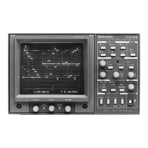
Operating Basics Figure 2–1: 1735 HD High Definition Waveform Monitor Clamp 2. CLAMP / GND This switch toggles between On and Off. When DC CPLG is selected, it controls the input ground relays (to ground the inputs for checking DC levels). -
Page 40: Vertical
CRT. To exit the dual filter mode, select either FLAT or FILTER with a momentary push of the button. The dual filter cannot be accessed when the 1735 HD is in THREE LINE or THREE FIELD sweep mode, LINE SELECT mode, or when more than one input is selected. -
Page 41: Horizontal
A momentary push of this switch toggles between MAG On and Off. It operates in conjunction with the LINE/FIELD and ONE/ TWO/THREE sweep modes to provide usable sweep rates as shown in Table 2–3. 2–4 1735 HD High Definition Waveform Monitor... -
Page 42: Power
All other rates listed in LINES / FRAME Menu Power 15. ON – OFF This switch turns the external power to the 1735 HD ON and OFF (standby). A mechanical indicator appears when the switch is in the ON position. Line Select 16. ON This On/Off push button enables the LINE SELECT mode. -
Page 43: Display
(push and hold the MAG / READOUT button), the CRT readout identifies the selected line. Push and hold both the UP and DOWN buttons to display a predefined line. Display 20. INTENSITY Use this control to adjust waveform display brightness. 2–6 1735 HD High Definition Waveform Monitor... -
Page 44: Configuring Menus
Use this control to adjust the CRT beam for optimum definition. Configuring Menus The 1735 HD allows a number of operational settings to be selected through the menu. With the exception of “TEST,” all items on the menu are used to configure the 1735 HD for specific measurement applications. -
Page 45: Lines / Frame
MENU. Use the UP / DOWN buttons to toggle between YES and NO. Selecting YES enables the 1735 HD to subtract the CH1B input from the front-panel selected inputs. Once selection is made, press MENU once to return to the main menu or twice to return to normal front-panel controlled operation. -
Page 46: Calibration
Turn input channels On / Off. b. Select sweep rates. c. Remote Sync input and enable. d. 10V RGB staircase input and enable. e. External Horizontal input and enable. Store and Recall. 2–9 1735 HD High Definition Waveform Monitor... -
Page 47: Figure 2-3: 1735 Hd Rear Panel
Operating Basics Remote functions are activated by polled ground closure. The 1735 HD only responds only to changes in the REMOTE status. This allows the front panel to remain fully operational during remote operation. For more details, refer to the heading “Remote Operation” in Installation. -
Page 48: Power Input
Replaceable Mechanical Parts list under Standard Accessories. Graticule The 1735 HD graticule is internally scribed on the same plane as the CRT phosphor to prevent parallax errors when viewing or photographing the displays. See Figure 2–4. -
Page 49: Horizontal Scale
Field rate sweeps do not assign an exact period of time to the graticule divisions. Front Panel Diagnostics The 1735 HD has several diagnostic routines that can be run to assist in locating operating system failures. Key to the diagnostics is the microcontroller. It tests... -
Page 50: Memory Test
NOVRAM (such as 2444), and the software copyright information. DAC (Digital-to-Analog Because the 1735 HD combines analog and digital capabilities, conversion from Converter) Test digital to analog signals is an essential operation for the microcontroller. To test this function, a test pattern (shown in Figure 2–6) is programmed into the... -
Page 51: Set Default Nvram
If performing the Operator’s Checkout Procedure reveals improper operation or instrument malfunction, first check the operation of the associated equipment. If the associated equipment is operating normally but the 1735 HD is not, it should be repaired or adjusted by qualified service personnel. -
Page 52: Figure 2-7: Initial Equipment Connections
Figure 2–7: Initial equipment connections 3. Apply Power Connect the 1735 HD to a suitable AC power source and push the POWER button. A dot should appear in the center of the button to indicate that the instrument is on. - Page 53 Check that the display blanking level is parallel to the horizontal axis. If it is not, adjust the TRACE ROTATION screwdriver adjustment until the sweep is parallel to the horizontal axis. 2–16 1735 HD High Definition Waveform Monitor...
-
Page 54: Figure 2-8: 2 Line Color Bar Display
When TEST is selected, the submenu presents a choice of tests, each of which may have a submenu to enable. More information regarding these tests is located in the preceding section called “FRONT PANEL DIAGNOSTICS.” 2–17 1735 HD High Definition Waveform Monitor... -
Page 55: Figure 2-9: 1735 Hd Calibrator Signal
EXT and no external reference signal applied to the instrument, the sweep will be free running rather than synchronized. c. Connect the TSG 1001 Sync Out to the 1735 HD rear-panel EXT connector and terminate the remaining side of the loop-through input with 75 W. -
Page 56: Table 2-5: Input Channels Displayed
). Be sure that all three TSG 1001 output channels are turned on. b. Connect the three outputs to the 1735 HD channels 1A, 1B, and 3A. Terminate the three loop-throughs in 75 W. c. Set the 1735 HD for a two-line display. -
Page 57: Figure 2-10: Side-By-Side Display Of The Three Input Channels
11. CH 2–CH 3 OFFSET a. Enable the offsets through the menu. b. Rotate the 1735 HD CH 2 and CH 3 OFFSET controls counterclockwise out of the detent position. c. Note that the channel 2 and channel 3 displays can be moved vertically with respect to each other and with respect to the channel 1 display. -
Page 58: Figure 2-11: Multiburst Signal; Two-Line Flat Display
Push and hold the FILTER button until both the FLAT and FILTER indicators light. Look for a display similar to that in Figure 2–12, with the flat display on the left and the filtered on the right. 2–21 1735 HD High Definition Waveform Monitor... -
Page 59: Figure 2-12: Multiburst Signal; Alternate Lines Filtered And Flat
Push the HORIZONTAL MAG button, and adjust the position control if necessary to return burst to the center of the graticule. 2–22 1735 HD High Definition Waveform Monitor... - Page 60 15. Channel 1B Subtract Mode a. Use a dual-input connector to feed the same signal to the 1735 HD CH 2B input as to the CH 1B input. Select CH 2B input for display.
-
Page 61: Figure 2-13: 1735 Hd On-Screen Readout For Line-Select Operation, With 14-Line Selected
TAL MAG/READOUT until the readout is displayed. (If the magnifier stays on when readout is displayed, momentarily push the MAG/ READOUT button.) Figure 2–13: 1735 HD on-screen readout for line-select operation, with 14-line selected b. Push the LINE SELECT ON button and observe the line number appearing in the upper left corner of the screen. - Page 62 Push the LINE SELECT DOWN button, hold it in, and watch the line numbers decrease. Hold the button in until lines from the vertical (field) interval are displayed. Push the LINE SELECT ON button to turn off the line select function. 2–25 1735 HD High Definition Waveform Monitor...
- Page 63 Operating Basics 2–26 1735 HD High Definition Waveform Monitor...
-
Page 64: Specifications
Specifications... -
Page 66: Table 3-1: Vertical Deflection System
Variable Gain Range +5 dB, –20 dB. Position Range 1 V signal can be positioned so that CLAMP on, any gain setting. pea k white or sync tip can be placed at blanking level. 3–1 1735 HD High Definition Waveform Monitor... - Page 67 75 W (Nominal). Output Impedance Return Loss (75 W) At least 26 dB, 50 kHz to 30 MHz. With instrument turned on. Input to PIX MON Output Gain Ratio 1:1 5% at 15 kHz. 3–2 1735 HD High Definition Waveform Monitor...
-
Page 68: Table 3-2: Dc Restoration
Equal to frame rate of applied video or external sync. 2 Field Sweep Equal to half frame rate of applied video or external sync. 1 Line Sweep Equal to line rate of applied video or external sync. 3–3 1735 HD High Definition Waveform Monitor... - Page 69 In Line Select, the number of the selected line is displayed in the upper left portion of the screen. If 14-LINE mode is also selected, [14] is shown to the right of the selected line number. 3–4 1735 HD High Definition Waveform Monitor...
-
Page 70: Table 3-5: Rgb/Yrgb Mode
THREELINE. Sweep Length 3-step: 3.4 – 4.1 div. Field or line rate sweeps. A 1FIELD sweep is selected by grounding the 4-step: 2.5 – 3.1 div. 1FIELD/1LINE pin of the rear-panel REMOTE connector. 3–5 1735 HD High Definition Waveform Monitor... -
Page 71: Table 3-6: External Horizontal
Remote sync bypasses sync stripper and field ID circuits. Remote Sync Polarity Internal jumper selects polarity. Normal: Negative-going edge line sync, positive edge of field sync. Inverted: Positive-going edge line sync, negative edge of field sync. 3–6 1735 HD High Definition Waveform Monitor... -
Page 72: Table 3-8: Crt Display
30 g’s, 1/2 sine, 11 ms duration, 3 shocks per surface (18 total). Transportation This product qualified under NSTA (National Safe Transit Association) preshipment test procedures, Project 1A–B–1. Humidity Will operate at 95% relative humidity for up to five days. 3–7 1735 HD High Definition Waveform Monitor... -
Page 73: Table 3-11: Physical Characteristics
IEC 801-4 Electrical Fast Transient/Burst Immunity High-quality shielded cables must be used to ensure compliance to the above listed standards. This product complies when installed into any of the following Tektronix instrument enclosures: 1700F00 Standard Cabinet 1700F02 Portable Cabinet 1700F05 Rack Adapter FCC Compliance Emissions comply with FCC Code of Federal Regulations 47, Part 15, Subpart B, Class A Limits. - Page 74 Class 1 (as defined in IEC 1010-1, Annex H) – grounded product Overvoltage Category Overvoltage Category II (as defined in IEC 1010-1, Annex J) Pollution Degree Pollution Degree 2 (as defined in IEC 1010-1). Note: Rated for indoor use only. 3–9 1735 HD High Definition Waveform Monitor...
- Page 75 Specifications 3–10 1735 HD High Definition Waveform Monitor...
- Page 76 WARNING The following servicing instructions are for use only by qualified personnel. To avoid injury, do not perform any servicing other than that stated in the operating instructions unless you are qualified to do so. Refer to all safety summaries before performing any service.
-
Page 78: Theory Of Operation
Theory of Operation... -
Page 80: Instrument Overview
Full line-select capability, with on-screen identification of selected rate and field/line, is provided for every field/line rate. The 1735 HD can be operated from AC mains over the range of 90–250 V, 48–66 Hz without operator adjustment. Block Diagram Overview... -
Page 81: Figure 4-1: Simplified Basic Block Diagram Of The
Theory of Operation Figure 4–1: Simplified basic block diagram of the 1735 HD High Definition Waveform Monitor A one-of-eight video switch (multiplexer) selects a video input, or a sequence of video inputs, to provide overlaid or parade displays, or a vertical calibration display. -
Page 82: Horizontal Deflection
LINES/FRAME selection in the menu. In addition, accommodation is made for remote sync input and enable through the rear-panel REMOTE connector. 4–3 1735 HD High Definition Waveform Monitor... -
Page 83: Low Voltage Power Supply
Diagrams <1>, <2>, and <3> Inputs. Each of the six video input channels of the 1735 HD has an identical video input amplifier. These channels are arranged in two groups of three each (1A-2A-3A and 1B-2B-3B). CH 1A circuit numbers are used here. - Page 84 (K1 for CH 1A) whenever it detects low power supply voltage. When power is switched off, the relays disconnect the video input amplifiers from the rear-panel video loop-through input, so video routed through the 1735 HD is not affected. These relays are also used to provide a ground level check controlled from the front panel.
-
Page 85: Video Multiplexer / Vertical Gain Diagram <4
Theory of Operation Sync Switch (for internal sync). The 1735 HD can use sync from the video on CH 1A or CH 1B, or from EXT SYNC on the rear panel. Sync from CH 1A is enabled by a current-mode switch. Common-base amplifier Q35 converts the video from CH 1A to a current signal. - Page 86 R128. When vertical variable gain is selected, control signal VARSEL to U30A and U30B switches from the front-panel CAL control to the front-panel VAR control. Summing amplifier U28B determines the nominal voltage and range for the VSIZE control signal for the gain cell. 4–7 1735 HD High Definition Waveform Monitor...
-
Page 87: Vertical Output Diagram <5
Vertical Limiter and Vertical Deflection. The vertical limiter, gain cell, and vertical level shift are in U25 (a Tektronix ASIC). The inverted 2X video from the filter switch is attenuated to 1X video by R64 and R137 at U25 pin 9. Analog control signals VSIZE and VMOVE control the gain cell and vertical level shift. -
Page 88: Horizontal Diagram <6
U23A is applied to inverting and non-inverting inputs to U26B so that the position control does not affect the readout. U23B is a comparator with its output (pin 7) high for sweep and low for readout. 4–9 1735 HD High Definition Waveform Monitor... - Page 89 U29A or B goes low and causes the CRT beam to be blanked. Q23 and Q21 form a fast pull-up to unblank the CRT when the beam comes back into the screen area. 4–10 1735 HD High Definition Waveform Monitor...
-
Page 90: Control / Post Regulators Diagram <7
Q4 is turned on, and current is drawn through DS100, DS200, and DS300 to ground. The duty cycle of Q4 is determined by the front-panel SCALE control. J1 is normally in the 1–2 position (lights enabled). In the 2–3 position, the graticule scale illumination is disabled. 4–11 1735 HD High Definition Waveform Monitor... -
Page 91: Table 4-1: Control Signals Grouped By Function
To meet the on-board needs of the 1735 HD Main (A3) circuit board, 10 V, 8 V, and 5 V are provided. The regulators are U1 and U11 (+10 V and 10 V supplies), U2 and U13 (+8 V and –8 V supplies), and U12 (–5 V supply). -
Page 92: Microcontroller Diagram <8
U31 is a tri-state octal D-Type latch which determines the address lines. The front-panel switch matrix is read directly by U33 through Port 1 which provides a stimulus via ROW 0–3, and evaluates the response through COL 0–3. 4–13 1735 HD High Definition Waveform Monitor... - Page 93 R156 and R145 adjust the position of the readout on the CRT. Readout gain adjustments are in the horizontal and vertical amplifier circuits. The horizontal and vertical readout is enabled by ROEN from Port 6 of U33. 4–14 1735 HD High Definition Waveform Monitor...
-
Page 94: Timing Diagram <9
Horizontal Sync Generator. The horizontal sync generator produces a pulse that starts just before sync and ends at the leading edge of sync. Since the 1735 HD is a multi-standard instrument, the time from the leading edge of sync to the start of the pulse is programmable and controlled by U33 (Diagram 8). - Page 95 The comparator thresholds are controlled by dual DAC U28. Back porch clamps are inhibited during broad pulses. They can also be inhibited directly by the slave processor to turn off the clamp pulses. 4–16 1735 HD High Definition Waveform Monitor...
-
Page 96: Figure 4-2: 1735 Hd Clamp Pulse Generator
Theory of Operation Figure 4–2: 1735 HD Clamp pulse generator 4–17 1735 HD High Definition Waveform Monitor... -
Page 97: Sync (Internal, External, & Remote) Diagram <10
C7 and R25 provide compensation. R6, R1, and R7 form a voltage divider that biases the bases of Q2 (at approxi- mately 4 V) and Q5 (at approximately 2 V). 4–18 1735 HD High Definition Waveform Monitor... - Page 98 J5. U3C generates the clock for U13B by ANDing remote sync with the microprocessor-generated REM SYNC EN. U13B is a JK flip-flop that is preset and cleared by the slave microprocessor (Diagram 11). 4–19 1735 HD High Definition Waveform Monitor...
-
Page 99: Input / Output Diagram <11
REMOTE input connector (J401) through J3. Both A0 and /RD from the master microprocessor must be low to read the TTL levels on J3. If either of these lines goes high, the buffer goes to the high impedance state. 4–20 1735 HD High Definition Waveform Monitor... - Page 100 U10A, pin 3 high. U14, pin 15 then directly controls sweep gating, through U10B. U12 is an 8-input D-Type flip-flop used as a latch for the slave microprocessor video input channel select and offset select control signals. 4–21 1735 HD High Definition Waveform Monitor...
-
Page 101: Display Diagram <12
Diagram <12> Trace Rotate. Trace rotation is necessary to compensate for changes in the magnetic field surrounding the 1735 HD. Q18 and Q19 are emitter followers that provide the trace rotation current to a coil located inside the CRT shield, around the tube. -
Page 102: Front Panel Diagram <13
The controller now knows that the depressed key is REF, and responds by turning on the front-panel REF LED and the associated control I/O. After finding a key condition, the controller debounces and checks again. 4–23 1735 HD High Definition Waveform Monitor... -
Page 103: Low Voltage Power Supply Diagram <14
AC line noise from affecting instrument performance, and to prevent any noise generated within the waveform monitor from getting back to the AC line. R125 and R131 provide surge protection, limiting initial turn-on current through the rectifier and capacitors. 4–24 1735 HD High Definition Waveform Monitor... - Page 104 R87. It holds the output of the controller to 5 V. The timing waveform for the internal 80 kHz oscillator is a sawtooth waveform whose repetition rate and slope are determined by C45 and R98. 4–25 1735 HD High Definition Waveform Monitor...
- Page 105 (+5 V and +40 V). The third winding is center tapped and outputs +15 V and 15 V. Each supply is rectified by a single diode (frequency is 80 kHz) and smoothed by an LC pi filter, consisting of a single inductor and 2 filter capaci- tors. 4–26 1735 HD High Definition Waveform Monitor...
-
Page 106: High Voltage Power Supply Diagram <15
High Voltage Power Supply Diagram <15> The High Voltage Power Supply generates the heater, cathode, control grid, focus anode, and post accelerating potentials required to display the outputs of the Vertical and Horizontal Output Amplifiers. 4–27 1735 HD High Definition Waveform Monitor... - Page 107 CRT Bias adjustment, R52; negative clipping level is set by the front-panel intensity control through the Z-axis amplifier. The clipped sine wave is coupled through C11 to a rectifier made up of CR4 and CR5. 4–28 1735 HD High Definition Waveform Monitor...
- Page 108 Q6 is the output of the Z-axis amplifier. C12 speeds up the constant current source, Q5, for the fast transitions of the blanking pulses. DS5 and DS3 are neon bulbs intended to prevent damage to the Z-axis amplifier if there is a CRT high voltage discharge. 4–29 1735 HD High Definition Waveform Monitor...
- Page 109 Theory of Operation 4–30 1735 HD High Definition Waveform Monitor...
-
Page 110: Performance Verification
Performance Verification... -
Page 112: Recommended Equipment List
Specification. Next is the Adjustment Procedure, used to return the instrument to operation within specifications. In both procedures, controls and connectors on the 1735 HD front panel and rear panel are fully capitalized (such as TWOLINE). Control and connector names on test equipment, as well as internal controls and adjustments for the instrument under test, are initial capitalized (such as Time/Div). - Page 113 Table 5–1: Recommended equipment list (Cont.) Description Requirements Example Voltmeter Range: 0 to greater than 100 VDC. Tektronix DM501A in a TM500 Series Power Accuracy: 0.1%. Module. Video Amplitude Calibrator Signal: adjustable square wave 0.0 mV to Tektronix 067–0916–00 in a TM500 Series 999.9 mV p-p with a resolution of 0.1 mV.
-
Page 114: Figure 5-1: Remote Connector Modified To Check Rgb Operation
BNC Female to Dual Banana Plug Tektronix Part No. 103–0090–00. Adapter RGB Test Connector 15-pin, subminiature, D-type connector modified as shown in Figure 5–1. Figure 5–1: REMOTE connector modified to check RGB operation 5–3 1735 HD High Definition Waveform Monitor... -
Page 115: Performance Check
17. Check PIX MON OUT Frequency Response 18. Check CH 1B Subtract 19. Check X1 Transient Response 20. Check X5 Transient Response 21. Check Square Wave Tilt 22. Check Noise Filter Response 23. Check Return Loss 5–4 1735 HD High Definition Waveform Monitor... -
Page 116: Standard Performance Check Procedure
(For example, push ONE and LINE for a one-line display.) 1. Preliminary Setup a. Connect the 1735 HD AC power cord to the variable autotransformer as shown in Figure 5–2. Turn power on and set the autotransformer for the voltage shown by the rear-panel line voltage indication. - Page 117 Check that a sweep occurs in all the horizontal sweep modes when no signals or external reference are applied to the instrument. b. Connect a 75 W cable from the TSG 1001 G/Y output to the 1735 HD CH 1A INPUT. Terminate the remaining side of the loop-through input in 75 W.
- Page 118 2%, Integral Linearity to within 1%. 0.2 ms/division (ONE LINE Sweep with MAG On), timing accuracy to within 3%. a. On the TSG 1001, select Zone Plates Signal Set, and press the Monitor Setup button. 5–7 1735 HD High Definition Waveform Monitor...
-
Page 119: Figure 5-3: Checking Horizontal Timing
Performance Verification b. Set the sine wave frequency to 100 kHz. c. Select CH 1A INPUT and TWO LINE Sweep on the 1735 HD. d. Use the 1735 HD VERTICAL and HORIZONTAL Position controls as needed to position the first line of the display so that the tips of the sine wave align with major divisions on the graticule blanking level. - Page 120 0.5 minor divisions of a major division graticule mark. m. Select ONE LINE Sweep and MAG Off on the 1735 HD. n. Set the TSG 1001 sine wave frequency to 200 kHz.
- Page 121 Enter the MENU and select EXT HORIZ NO. Exit the MENU. e. Disconnect the REMOTE connector and the TSG 1001 signal from the 1735 HD. (Leave the EXT REF connections in place.) 5–10 1735 HD High Definition Waveform Monitor...
- Page 122 1 V peak-to-peak within a tolerance of 1%. X5 Gain within 5% with 200 mV input. a. Connect a 999.9 mV signal from the VAC to the 1735 HD CH 1A INPUT. Leave the loop-through unterminated.
- Page 123 Set the VAC Amplitude to 999.9 mV and select ONE LINE Sweep on the 1735 HD. b. Connect a 75 W cable with a 75 W in-line termination from the 1735 HD rear-panel PIX MON OUT to the test oscilloscope vertical input.
- Page 124 Check CH 1A, CH 2A, and CH 3A for a DC level of 0 V, 1 mV as viewed on the 1735 HD. d. Select the B INPUT on the 1735 HD. 5–13 1735 HD High Definition Waveform Monitor...
- Page 125 Connect the TSG 1001 G/Y output to the 1735 HD CH 1A INPUT. Select CH 1A INPUT, INT REF, and TWO LINE Sweep. m. Position the blanking level to the 0 V graticule line on the 1735 HD, and turn the CLAMP On.
- Page 126 50 Hz signal; Fast Clamp removes >95% of 50 Hz signal. Blanking level shift with APL change, less than 1% (7 mV). a. Connect the Sync Out signal from the TSG1001 to the 1735 HD EXT REF Input. b. Connect a 50 W precision cable and 50–75 W minimum loss attenuator from the output of the function generator to the 1735 HD CH 1A INPUT.
- Page 127 1735 HD. d. Set the leveled sine-wave generator Frequency Range to 50 kHz and adjust its Output Amplitude for a 700 mV display on the 1735 HD. e. Set the DVM range for three-place accuracy and adjust the peak-to-peak detector + level for a reading as close to zero as possible. Note the reference reading.
- Page 128 Select CH 1A INPUT on the 1735 HD. d. Set the leveled sine-wave generator Frequency Range to 50 kHz and adjust its Output Amplitude for a 700 mV display on the 1735 HD. e. Set the DVM range for three-place accuracy and adjust the peak-to-peak detector level for a reading as close to zero as possible.
- Page 129 CH 1A INPUT on the 1735 HD. b. Connect the Trigger Out from the PG506A to the 1735 HD EXT REF Input. Set the PG506A for a 0.1 ms period.
- Page 130 21. Check Square Wave Tilt Requirement: Field Rate Square Wave or Vertical Window, 1% or less tilt. a. Connect the TSG 1001 G/Y output to the 1735 HD CH 1A INPUT. Terminate the loop-through in 75 W. b. Select a Field-Rate Square Wave signal with a 700 mV bar amplitude.
- Page 131 Performance Verification d. Enter the 1735 HD MENU and select NOISE FILTER. Exit the MENU. e. Switch back and forth between FILTER and FLAT Filter. Check that the amplitude of the display in FILTER, is within 1% of the displayed amplitude in the FLAT Filter mode.
- Page 132 Check for a Reference Level Readout on the spectrum analyzer of >35 dBm. u. On the 1735 HD, switch between GND Off and On and check that the Reference Level Readout on the spectrum analyzer does not change by more than 2 dBm.
- Page 133 Performance Verification aa. Check for a Reference Level Readout on the spectrum analyzer of >26 dBm. This concludes the Performance Checks Procedure. 5–22 1735 HD High Definition Waveform Monitor...
-
Page 134: Adjustment Procedure
Adjustment Procedure... -
Page 136: Short-Form Procedure
A3C262). 11. Adjust Low-Frequency Input Compensation (A3R447–A3C139, A3R432–A3C126, A3R459–A3C119, A3R440–A3C103, A3R466–A3C135, A3R468–A3C137). 12. Adjust DC Coupled Position (A3R330, A3R304, A3R308, A3R277, A3R315, A3R326). 13. Adjust Clamped Position (A3R313, A3R354, A3R372, A3R358, A3R348, A3R349). 6–1 1735 HD High Definition Waveform Monitor... -
Page 137: Figure 6-1: (A) Adjustment Locations On The Power Supply
Adjustment Procedure Figure 6–1: (A) Adjustment locations on the Power Supply circuit board (Assembly A1). (B) Adjustment locations on the Control circuit board 6–2 1735 HD High Definition Waveform Monitor... - Page 138 Adjustment Procedure Figure 6–2: Adjustment locations on the Main circuit board (Assembly A3) 6–3 1735 HD High Definition Waveform Monitor...
- Page 139 26. Adjust Diff Step Filter Response (A3R567, A3L2, A3L4). 27. Adjust Timing (A3R158, A3R163, A3R164). 28. Adjust MAG Registration (A3R78). 29. Adjust RGB/YRGB Display (A3R89, A3R92, A3C57). 30. Adjust CRT Bias (A3R6, A1R52). 31. Adjust CRT Readout (A4R156, A4R145, A3R579, A3R6). 6–4 1735 HD High Definition Waveform Monitor...
-
Page 140: Standard Adjustment Procedure
FLAT – FILTER FLAT HORIZONTAL ONE – TWO – THREE LINE – FIELD LINE MAG – READOUT LINE SELECT MENU MENU SETTINGS OFFSETS DISABLED FOCUS as desired SCALE as desired INTENS as desired 6–5 1735 HD High Definition Waveform Monitor... -
Page 141: Power Supply Board (A1)
Refer to Figure 6–1A. 1. Adjust +5 Volts Supply a. Connect a 75 W cable from the TSG 1001 G/Y Output to the 1735 HD CH 1A INPUT. Terminate the remaining side of the loop-through input with a 75 W terminator. Select the NTSC Format SMPTE Bars signal from the TSG 1001. -
Page 142: Power Supply Board (A1)
Select CH 1A INPUT on the 1735 HD. 6. Adjust Center Focus, Astigmatism, and Geometry a. Select the 1735 HD MENU. The MENU readout will be displayed on screen. 6–7 1735 HD High Definition Waveform Monitor... -
Page 143: Control Board (A4)
A4R156 will be adjusted more precisely in a later step.) c. Select TEST, then DAC TEST from the MENU. d. Set the 1735 HD front-panel FOCUS control to approximately mid range. e. Adjust A1R10 (Center Focus) and A1R43 (Astig) for the most clearly defined display. - Page 144 Connect a X10 probe from the test oscilloscope Ch 1 Input to A3U36, pin1. See Figure 6–2. b. Connect a 75 W cable with a 75 W in-line terminator from the 1735 HD PIX MON OUT to the test oscilloscope Ch2 Input.
-
Page 145: Main Board (A3)
Remove one of the cables from the RF Bridge. Set the spectrum analyzer cursor to 30 MHz and then set the marker to 30 MHz. k. Reconnect the cable to the RF Bridge. Note the Reference Level Readout. 6–10 1735 HD High Definition Waveform Monitor... -
Page 146: Table 6-2: Return Loss Adjustments
Adjust A3C257 for a Reference Level Readout on the spectrum analyzer of >35 dBm. u. On the 1735 HD, switch between GND Off and On and check that the Reference Level Readout on the spectrum analyzer does not change by more than 2 dBm. -
Page 147: Table 6-3: Flat Response Adjustments
Connect a Field-Rate Square Wave signal from the TSG 1001 to the CH 1A INPUT. c. Connect a X10 probe from A3TP3 on the 1735 HD to the test oscillo- scope CH1 input. d. Set the test oscilloscope as follows:... - Page 148 0 V graticule line. Deselect the DC CPLG. 13. Adjust Clamped Position a. Turn On the 1735 HD CLAMP and turn Off all INPUTs. b. Use the VERTICAL Position control to position the trace on the 0 V graticule line.
- Page 149 Remove all cables and terminators from the 1735 HD. 15. Adjust X1 Flat Gain a. Connect the VAC to the CH 1A INPUT on the 1735 HD. Do not terminate the loop-through. Set the VAC for a 999.9 mV signal output.
- Page 150 Remove the signal cable from the 1735 HD. 17. Adjust X5 Mag Registration a. Connect the TSG 1001 G/Y output to the 1735 HD CH 1A INPUT and terminate the loop-through in 75 W. b. Select the NTSC format 5-Step Linearity signal from the TSG 1001.
- Page 151 1735 HD. d. Set the leveled sine wave generator Frequency Range to 50 kHz and adjust its Output Amplitude for a 700 mV display on the 1735 HD. e. Set the DVM range for three-place accuracy and adjust the peak-to-peak detector + level for a reading as close to zero as possible.
- Page 152 Return 1735 HD to X1 Gain. 21. Check PIX MON OUT Frequency Response a. Connect the peak-to-peak detector head to the 1735 HD PIX MON OUT connector. b. Connect the leveled sine wave generator to the 1735 HD CH 1A.
- Page 153 Enter the 1735 HD MENU, select SUBTRACT NO, and exit the MENU. 24. Adjust Filter Gain a. Connect the VAC output to the 1735 HD CH 1A INPUT. Do not terminate. b. Set the VAC to 999.9 mV. c. Select the 1735 HD CH 1A INPUT, FLAT Filter, and ONE LINE Sweep.
- Page 154 Disconnect the PG506A from the 1735 HD. 27. Adjust Timing a. Connect the TSG 1001 G/Y Output to the 1735 HD CH 1A INPUT. Terminate the loop-through in 75 W. b. Set the TSG 1001 to the Zone Plate signal set, 525/59.94/2:1 Formats, and press the Monitor Setup button.
- Page 155 Adjust A3R163 (1 ms Timing) for one cycle/major division over the center 10 divisions of the display. k. Select ONE LINE Sweep on the 1735 HD. Set the TSG 1001 sine wave frequency to 5 MHz. m. Adjust A3R164 (0.1 ms Timing) for one cycle/major division over the center 10 divisions, 3%.
- Page 156 Adjust A3C57 (RGB Comp) for best transient response and no smearing. r. Enter the MENU, deselect EXT HORIZONTAL, and exit the MENU. s. Remove the remote cable from the 1735 HD. 30. Adjust CRT Bias a. Turn READOUT and LINE SELECT READOUT On. Select Line19.
- Page 157 Adjust A3R6 (Line Select Focus) for best definition of the readout characters. e. Turn off LINE SELECT. Figure 6–7: A sample 1735 HD readout correctly positioned on the CRT This completes the Adjustment Procedure. 6–22 1735 HD High Definition Waveform Monitor...
-
Page 158: Maintenance
Maintenance... -
Page 160: Preventive Maintenance
Loosen dust with a soft, dry brush and remove it with low-pressure air (high-ve- locity air can damage some parts). Hardened dirt or grease can be removed with a cotton-tipped applicator dampened with a mild detergent and water solution. Abrasive cleaners should not be used. 7–1 1735 HD High Definition Waveform Monitor... -
Page 161: Visual Inspection
SCHOTTKY SIGNAL DIODES 250 V SCHOTTKY TTL 500 V HF BIPOLAR TRANSISTORS 400 to 600 V JFETS 600 to 800 V LINEAR CIRCUITS 400 to 1000 V est. LOW POWER SCHOTTKY TTL 900 V 7–2 1735 HD High Definition Waveform Monitor... - Page 162 8. Avoid handling components in areas that have a floor or work surface covering capable of generating a static charge. 9. Use a soldering iron that is connected to earth ground. 10. Use only wick-type or special antistatic suction desoldering tools. 7–3 1735 HD High Definition Waveform Monitor...
- Page 163 Preventive Maintenance 7–4 1735 HD High Definition Waveform Monitor...
-
Page 164: Troubleshooting
Symbols used on these diagrams are defined on the first page of the Diagrams section. Circuit boards are indicated by a heavy border. Refer to the Replaceable Electrical Parts for a complete description of each component. 7–5 1735 HD High Definition Waveform Monitor... - Page 165 NOTE. Always check the parts list for part numbers and descriptions when ordering replacement parts. Some parts may have been replaced or have a different value in an individual instrument. 7–6 1735 HD High Definition Waveform Monitor...
-
Page 166: Parts List
Accessories List. Standard accessories are illustrated in the exploded view drawing. Part numbers of standard and optional accessories are given at the end of the Replaceable Mechanical Parts. 7–7 1735 HD High Definition Waveform Monitor... -
Page 167: Major Assembly Interconnection
Pin 1 is marked by a triangular symbol on the circuit board and on the connector. Connectors with Center These polarizers serve as a key for proper mating with the connector on the Polarizers circuit board. Pin 1 is also marked with a triangular symbol on both connectors. 7–8 1735 HD High Definition Waveform Monitor... - Page 168 Troubleshooting Figure 7–3: Multiple pin connectors 7–9 1735 HD High Definition Waveform Monitor...
-
Page 169: General Troubleshooting Techniques
6. Determine the extent of the repair. If the necessary repair is complex, it may be advisable to contact your local Tektronix field office or representative before continuing. If the repair is minor, such as replacing a component, see the parts list for replacement information. -
Page 170: Corrective Maintenance
After any repair, circuit readjustment may be required. Selected Components The 1735 HD has only one test selectable part. Capacitor C255 on the A3 Main board has a nominal value of 22 pF. If necessary to meet the CH 3A Subtract specification, this capacitor may be changed to 15 pF. -
Page 171: Mechanical Disassembly/Assembly
NOTE. All screws, unless otherwise noted, are TORXR screws and can be removed with a T15 screwdriver tip (Tektronix part number 003–0966–00). The exception is #2 PozidriveR screws which can be removed with a #1 PozidriveR tip (003–0443–00). -
Page 172: Graticule Light Tools
PL317 (longer than PL312). CAUTION. Needle-nosed pliers are not recommended. Replacement bulbs are supplied with this instrument as Standard Accessories. Additional bulbs can be purchased from Tektronix (see Replaceable Electrical Parts) or from local electronics distribution sources. Graticule Light 1. Remove the bezel according to the preceding instructions. -
Page 173: Replacement Of The Crt
8. Connect all four deflection leads (red, green, blue, and brown) to the CRT. See Figure 7–5. 9. Clean the face of the CRT to remove fingerprints. 10. Reconnect the anode connector to the HV Multiplier on the Power Supply board. 11. Install the bezel. 7–14 1735 HD High Definition Waveform Monitor... -
Page 174: Removing The Rear-Panel Assembly
4. Disconnect the cable from J243 on the BNC board. 5. Disconnect the cable from J501 on the Power Supply board. 6. Remove the two screws and nuts (with captive lockwashers) from the ac line filter. See Figure 7–6. 7–15 1735 HD High Definition Waveform Monitor... -
Page 175: Separating Bnc Board From Rear Panel
2. Remove the two screws located above and below the Front Panel board as shown in Figure 7–7. Remove the front-panel assembly, including the Front Panel board, by pushing it through the opening in the frame. 7–16 1735 HD High Definition Waveform Monitor... -
Page 176: Removing The Control Board
Main board). 3. Raise the Control board sufficiently to disconnect the ribbon cable connec- tors from J3, J4, J5, J6. 4. Disconnect the cable from J1 on the Control board. Remove the Control board. 7–17 1735 HD High Definition Waveform Monitor... -
Page 177: Removing The Main Board
Corrective Maintenance Removing the Main Board 1. Unsolder the wires (Tektronix part number 196–3146–00) from the following 12 locations on the BNC board: P605, P607, P609, P615, P619, P625, P629, P635, P639, P645, P647, and P649. 2. If the Main board is to be replaced, remove the wires and install them on the replacement board. -
Page 178: Removing The Power Supply Board
6. Remove the seven screws that hold the Power Supply board in place. See Figure 7–9. 7. Remove the board by sliding it toward the front panel and lifting it up. Figure 7–9: Screws that hold the Power Supply board (A1) in place 7–19 1735 HD High Definition Waveform Monitor... - Page 179 Corrective Maintenance 7–20 1735 HD High Definition Waveform Monitor...
-
Page 180: Repackaging
Repackaging Identification Tag If the instrument is to be shipped to a Tektronix Service Center for service or repair, attach a tag to the instrument showing: 1. Owner (with complete address) and the name of the person at your firm that can be contacted. - Page 181 Repackaging Figure 7–10: Repackaging 7–22 1735 HD High Definition Waveform Monitor...
-
Page 182: Replaceable Electrical Parts
Replaceable Electrical Parts... - Page 184 Replaceable Electrical Parts This section contains a list of the electrical components for the 1735 HD. Use this list to identify and order replacement parts. Parts Ordering Information Replacement parts are available through your local Tektronix field office or representative.
- Page 185 Chassis-mounted parts have no assembly number prefix, and they are located at the end of the electrical parts list. Tektronix part number Use this part number when ordering replacement parts from Tektronix. 3 and 4 Serial number Column three indicates the serial number at which the part was first effective. Column four indicates the serial number at which the part was discontinued.
- Page 186 GREEN CASTLE, IN 46135 PO BOX 240 50434 HEWLETT–PACKARD CO 370 W TRIMBLE RD SAN JOSE CA 95131–1008 OPTOELECTRONICS DIV 50444 HEWLETT–PACKARD CO 1501 PAGE MILL RD PALO ALTO CA 94304–1126 H P LABORATORIES 8–1 1735 HD High Definition Waveform Monitor...
- Page 187 TK1462 YAMAICHI ELECTRONICS CO LTD 3–CHROME SHIBAURA TOKYO JAPAN 2ND FLOOR NEW KYOEI MINATO–KU BLDG 17–11 TK1913 WIMA 2269 SAW MILL RIVER ROAD ELMSFORD NY 10523 THE INTER–TECHNICAL GROUP IND PO BOX 127 8–2 1735 HD High Definition Waveform Monitor...
- Page 188 A2A1 671–0573–05 CIRCUIT BD ASSY:LED 80009 671–0573–05 672–1375–04 CIRCUIT BD ASSY:MAIN 80009 672–1375–04 A3A1 671–1796–01 CIRCUIT BD ASSY:GRATICULE LIGHT 80009 671–1796–01 671–2480–04 CIRCUIT BD ASSY:CONTROL 80009 671–2480–04 671–2481–00 CIRCUIT BD ASSY:BNC 80009 671–2481–00 8–3 1735 HD High Definition Waveform Monitor...
- Page 189 671–2271–02 CAP,FXD,AL:10UF,20%,160V,60 X 20;105 DEG,RDL,.2 LEADS 80009 290–1276–00 A1C25 290–1310–00 671–2271–02 CAP,FXD,ALUM:10UF,20%,160V,13 X 20MM;RDL,0.2LS,105 80009 290–1310–00 DEG,5000 HR A1C26 290–0920–00 CAP,FXD,ALUM:33UF,20%,50V,6 X 62643 SME50VB33RM6X11 11MM,0.1SP,RADIAL,BULK A1C27 283–0339–00 CAP,FXD,CER:MLC;0.22UF,10%,50V,X7R,0.30 X 0.30,0.20 LS 04222 SR305C224KAA 8–4 1735 HD High Definition Waveform Monitor...
- Page 190 281–0925–01 CAP,FXD,CER:MLC;0.22UF,20%,50V,Z5U.0.170 X 0.120;AX- 04222 SA115E224MAA IAL,MI A1C57 281–0759–00 CAP,FXD,CER:MLC;22PF,10%,100V,0.100 X 0.170;AXIAL,MI 80009 281–0759–00 A1C58 281–0775–01 CAP,FXD,CER:MCL;0.1UF,20%,50V,Z5U,0.170 X 0.100;AXIAL 04222 SA105E104MAA A1C59 281–0765–00 CAP,FXD,CER DI:100PF,5%,100V 04222 SA102A101JAA A1C60 281–0765–00 CAP,FXD,CER DI:100PF,5%,100V 04222 SA102A101JAA 8–5 1735 HD High Definition Waveform Monitor...
- Page 191 HTSK,XSTR:TO–220 W/SOLDERABLE TABS,AL 80009 214–3841–00 *END MOUNTING PARTS* A1CR18 152–0720–00 DIO,RECT:ULTRA FAST;100V,8A,25NS,100A 80009 152–0720–00 IFSM;BYW29–100,TO–220 *MOUNTING PARTS* 210–0406–00 NUT,PLAIN,HEX:4–40 X 0.188,BRS CD PL 73743 12161–50 211–0008–00 SCR,MACH:4–40 X 0.25,PNH,STL 93907 ORDER BY DESCR 8–6 1735 HD High Definition Waveform Monitor...
- Page 192 131–5337–00 CONN,HDR: 80009 131–5337–00 A1J5 131–3392–00 CONN,HDR:PCB;MALE,STR,1 X 10,0.1 CTR,0.230 MLG X 80009 131–3392–00 0.120 TAIL,30 GLD,BD RETENTION A1J7 131–4794–00 CONN,HDR:PCB;MALE,STR,1 X 2,0.1 CTR,0.235 MLG X 80009 131–4794–00 0.112 TAIL,30 GLD,0.035 DIA PCB 8–7 1735 HD High Definition Waveform Monitor...
- Page 193 80009 151–0188–00 AMPL;2N3906,TO–92 EBC A1Q4 151–0190–00 XSTR,SIG:BIPOLAR,NPN;40V,200MA,300MHZ, 80009 151–0190–00 AMPL;2N3904,TO–92 EBC A1Q5 151–0350–00 XSTR,SIG:BIPOLAR,PNP;150V,600MA,100MHZ, 04713 2N5401 AMPL;2N5401,TO–92 EBC A1Q6 151–0347–00 XSTR,SIG:BIPOLAR,NPN;160V,600MA,100MHZ, 80009 151–0347–00 AMPL;2N5551,TO–92 EBC A1Q7 151–0476–00 XSTR,PWR:BIPOLAR,NPN;100V,3.0A,3.0MHZ, 80009 151–0476–00 AMPL;TIP31C,TO–220 *MOUNTING PARTS* 8–8 1735 HD High Definition Waveform Monitor...
- Page 194 322–3344–00 RES,FXD,FILM:37.4K OHM,1%,0.2W,TC=T0 80009 322–3344–00 A1R6 322–3251–00 RES,FXD,FILM:4.02K OHM,1%,0.2W,TC=T0 57668 CRB20 FXE 4K02 A1R9 322–3097–00 RES,FXD:MET FILM;100 OHM,1%,0.2W,TC=100 PPM;AX- 57668 CRB20 FXE 100E IAL,T&R,SM BODY A1R10 311–1256–00 RES,VAR,TRMR:CERMET;2.5M OHM,10%,0.5W,0.375 80009 311–1256–00 SQ,TOP ADJUST;BULK 8–9 1735 HD High Definition Waveform Monitor...
- Page 195 RES,FXD:MET FILM;6.81K OHM,1%,0.2W,TC=100 PPM;AX- 80009 322–3273–00 IAL,T&R,SM BODY A1R36 315–0102–03 RES,FXD,CMPSN:1K OHM,5%,0.25W 80009 315–0102–03 A1R37 322–3385–00 RES,FXD:MET FILM;100K OHM,1%,0.2W,TC=100 PPM;AX- 57668 CRB20 FXE 100K IAL,T&R,SM BODY A1R38 311–2239–00 RES,VAR,TRMR:CERMET;100K OHM,20%,0.5W,0.197 TK1450 GF06UT 100K SQ,SIDE ADJUST;T&R 8–10 1735 HD High Definition Waveform Monitor...
- Page 196 322–3201–00 RES,FXD:MET FILM;1.21K OHM,1%,0.2W,TC=100 PPM;AX- 80009 322–3201–00 IAL,T&R,SM BODY A1R63 322–3385–00 RES,FXD:MET FILM;100K OHM,1%,0.2W,TC=100 PPM;AX- 57668 CRB20 FXE 100K IAL,T&R,SM BODY A1R64 322–3385–00 RES,FXD:MET FILM;100K OHM,1%,0.2W,TC=100 PPM;AX- 57668 CRB20 FXE 100K IAL,T&R,SM BODY 8–11 1735 HD High Definition Waveform Monitor...
- Page 197 RES,FXD:0.51 OHM,5%,1WTC=150PPM/DEG C,MI 80009 308–0793–00 A1R91 322–3193–00 RES,FXD:MET FILM;1K OHM,1%,0.2W,TC=100 PPM;AX- 57668 CRB20 FXE 1K00 IAL,T&R,SM BODY A1R92 322–3239–00 RES,FXD,FILM:3.01K OHM,1%,0.2W,TC=T0 57668 CRB20 FXE 3K01 A1R93 322–3121–00 RES,FXD:MET FILM;178 OHM,1%,0.2W,TC=100 PPM;AX- 80009 322–3121–00 IAL,T&R,SM BODY 8–12 1735 HD High Definition Waveform Monitor...
- Page 198 322–3350–00 A1R118 322–3277–00 RES,FXD,FILM:7.5K OHM,1%,0.2W,TC=T0 57668 CRB20 FXE 7K50 A1R119 322–3193–00 RES,FXD:MET FILM;1K OHM,1%,0.2W,TC=100 PPM;AX- 57668 CRB20 FXE 1K00 IAL,T&R,SM BODY A1R120 322–3452–00 RES,FXD,FILM:499K OHM,1%,0.2W,TC=TO 91637 CCF50–2–G4993FT A1R121 322–3452–00 RES,FXD,FILM:499K OHM,1%,0.2W,TC=TO 91637 CCF50–2–G4993FT 8–13 1735 HD High Definition Waveform Monitor...
- Page 199 DIO,ZENER:5.1V,5%,0.4W;1N751A FMLY,DO–35 OR 7 80009 152–0195–00 A1W61 131–0566–00 BUS,CNDCT:DUM RES,0.094 OD X 0.225 L 80009 131–0566–00 A1W67 131–0566–00 BUS,CNDCT:DUM RES,0.094 OD X 0.225 L 80009 131–0566–00 A1W68 131–0566–00 BUS,CNDCT:DUM RES,0.094 OD X 0.225 L 80009 131–0566–00 8–14 1735 HD High Definition Waveform Monitor...
- Page 200 SW,SIG:SPST;PUSH,MOM,NO,W/GND TERM,MNL INSER- 34361 B3F1152 TION,100 GRAMS,SIL,SLD;B3F1152 A2S230 260–2300–00 SW,SIG:SPST;PUSH,MOM,NO,W/GND TERM,MNL INSER- 34361 B3F1152 TION,100 GRAMS,SIL,SLD;B3F1152 A2S240 260–2300–00 SW,SIG:SPST;PUSH,MOM,NO,W/GND TERM,MNL INSER- 34361 B3F1152 TION,100 GRAMS,SIL,SLD;B3F1152 A2S410 260–2300–00 SW,SIG:SPST;PUSH,MOM,NO,W/GND TERM,MNL INSER- 34361 B3F1152 TION,100 GRAMS,SIL,SLD;B3F1152 8–15 1735 HD High Definition Waveform Monitor...
- Page 201 DIO,OPTO:LED;GRN,569NM,1MCD AT 10MA,90 DEG VIEW 80009 150–5003–00 ANGL,YOKE LEADBEND;HLMP–6500–T21,T&R A2A1DS514 150–5006–00 DIO,OPTO: 80009 150–5006–00 A2A1DS530 150–5003–00 DIO,OPTO:LED;GRN,569NM,1MCD AT 10MA,90 DEG VIEW 80009 150–5003–00 ANGL,YOKE LEADBEND;HLMP–6500–T21,T&R A2A1DS531 150–5003–00 DIO,OPTO:LED;GRN,569NM,1MCD AT 10MA,90 DEG VIEW 80009 150–5003–00 ANGL,YOKE LEADBEND;HLMP–6500–T21,T&R 8–16 1735 HD High Definition Waveform Monitor...
- Page 202 PPM;1206,T&R A2A1R520 321–5021–00 RES,FXD:THK FILM;1.82K OHM,1%,0.125W,TC=100 80009 321–5021–00 PPM;1206,T&R A2A1R521 321–5021–00 RES,FXD:THK FILM;1.82K OHM,1%,0.125W,TC=100 80009 321–5021–00 PPM;1206,T&R A2A1R522 321–5021–00 RES,FXD:THK FILM;1.82K OHM,1%,0.125W,TC=100 80009 321–5021–00 PPM;1206,T&R A2A1R523 321–5021–00 RES,FXD:THK FILM;1.82K OHM,1%,0.125W,TC=100 80009 321–5021–00 PPM;1206,T&R 8–17 1735 HD High Definition Waveform Monitor...
- Page 203 A2A1R527 321–5021–00 RES,FXD:THK FILM;1.82K OHM,1%,0.125W,TC=100 80009 321–5021–00 PPM;1206,T&R A2A1R530 321–5021–00 RES,FXD:THK FILM;1.82K OHM,1%,0.125W,TC=100 80009 321–5021–00 PPM;1206,T&R A2A1R531 321–5021–00 RES,FXD:THK FILM;1.82K OHM,1%,0.125W,TC=100 80009 321–5021–00 PPM;1206,T&R A2A1W395 174–1195–00 CA ASSY,SP,ELEC:10 CON,8.0 L,FLAT FLEX 80009 174–1195–00 8–18 1735 HD High Definition Waveform Monitor...
- Page 204 80009 281–0184–00 A3C27 283–0594–02 CAP,FXD,MICA DI:1000PF,1%,100V,T&A 09023 CDA15FA102F03 A3C28 281–0775–01 CAP,FXD,CER:MCL;0.1UF,20%,50V,Z5U,0.170 X 0.100;AXIAL 04222 SA105E104MAA A3C29 290–1295–00 CAP,FXD,ALUM:10UF,20%,16V,5 X 9 MM;RDL,105 DEG,BULK 80009 290–1295–00 A3C30 290–1295–00 CAP,FXD,ALUM:10UF,20%,16V,5 X 9 MM;RDL,105 DEG,BULK 80009 290–1295–00 8–19 1735 HD High Definition Waveform Monitor...
- Page 205 A3C64 281–0775–01 CAP,FXD,CER:MCL;0.1UF,20%,50V,Z5U,0.170 X 0.100;AXIAL 04222 SA105E104MAA A3C65 281–0775–01 CAP,FXD,CER:MCL;0.1UF,20%,50V,Z5U,0.170 X 0.100;AXIAL 04222 SA105E104MAA A3C66 281–0775–01 CAP,FXD,CER:MCL;0.1UF,20%,50V,Z5U,0.170 X 0.100;AXIAL 04222 SA105E104MAA A3C67 283–0059–02 CAP,FXD,CER DI:1UF,20%,50V,X7R 04222 SR305C105MAAAP1 A3C68 281–0798–00 CAP,FXD,CER DI:51PF,1%,100V 80009 281–0798–00 8–20 1735 HD High Definition Waveform Monitor...
- Page 206 CAP,FXD,CER:MLC;0.47UF,20%,50V,0.150 X 0.290;AXIAL,MI 80009 281–0563–00 A3C105 281–0775–01 CAP,FXD,CER:MCL;0.1UF,20%,50V,Z5U,0.170 X 0.100;AXIAL 04222 SA105E104MAA A3C106 281–0920–00 CAP,FXD:CER,MLC,1000PF,5%,50V,0.170 X 0.1;NPO,AXIAL 80009 281–0920–00 A3C107 281–0920–00 CAP,FXD:CER,MLC,1000PF,5%,50V,0.170 X 0.1;NPO,AXIAL 80009 281–0920–00 A3C108 281–0775–01 CAP,FXD,CER:MCL;0.1UF,20%,50V,Z5U,0.170 X 0.100;AXIAL 04222 SA105E104MAA 8–21 1735 HD High Definition Waveform Monitor...
- Page 207 281–0775–01 CAP,FXD,CER:MCL;0.1UF,20%,50V,Z5U,0.170 X 0.100;AXIAL 04222 SA105E104MAA A3C143 281–0775–01 CAP,FXD,CER:MCL;0.1UF,20%,50V,Z5U,0.170 X 0.100;AXIAL 04222 SA105E104MAA A3C144 281–0123–00 CAP,VAR,CER DI:5–25PF,100V 59660 518–000A5–25 A3C145 281–0775–01 CAP,FXD,CER:MCL;0.1UF,20%,50V,Z5U,0.170 X 0.100;AXIAL 04222 SA105E104MAA A3C146 281–0920–00 CAP,FXD:CER,MLC,1000PF,5%,50V,0.170 X 0.1;NPO,AXIAL 80009 281–0920–00 8–22 1735 HD High Definition Waveform Monitor...
- Page 208 281–0759–00 CAP,FXD,CER:MLC;22PF,10%,100V,0.100 X 0.170;AXIAL,MI 80009 281–0759–00 A3C181 281–0775–01 CAP,FXD,CER:MCL;0.1UF,20%,50V,Z5U,0.170 X 0.100;AXIAL 04222 SA105E104MAA A3C182 281–0928–00 CAP,FXD,CER DI:150PF,5% 04222 SA101A151JAA A3C183 281–0775–01 CAP,FXD,CER:MCL;0.1UF,20%,50V,Z5U,0.170 X 0.100;AXIAL 04222 SA105E104MAA A3C184 281–0920–00 CAP,FXD:CER,MLC,1000PF,5%,50V,0.170 X 0.1;NPO,AXIAL 80009 281–0920–00 8–23 1735 HD High Definition Waveform Monitor...
- Page 209 A3C215 281–0767–00 CAP,FXD,CER:MLC;330PF,20%,100V,0.100 X 0.170;AXIAL,MI 04222 SA102C331MAA A3C216 281–0910–00 CAP,FXD,CER DI:1800PF,1%,50V 04222 MA205A182FAA A3C217 281–0767–00 CAP,FXD,CER:MLC;330PF,20%,100V,0.100 X 0.170;AXIAL,MI 04222 SA102C331MAA A3C218 281–0910–00 CAP,FXD,CER DI:1800PF,1%,50V 04222 MA205A182FAA A3C219 281–0775–01 CAP,FXD,CER:MCL;0.1UF,20%,50V,Z5U,0.170 X 0.100;AXIAL 04222 SA105E104MAA 8–24 1735 HD High Definition Waveform Monitor...
- Page 210 80009 281–0903–00 A3C253 281–0903–00 CAP,FXD,CER DI:3.9PF,100V 80009 281–0903–00 A3C254 281–0903–00 CAP,FXD,CER DI:3.9PF,100V 80009 281–0903–00 A3C255 281–0759–00 CAP,FXD,CER:MLC;22PF,10%,100V,0.100 X 0.170;AXIAL,MI 80009 281–0759–00 A3C256 281–0775–01 CAP,FXD,CER:MCL;0.1UF,20%,50V,Z5U,0.170 X 0.100;AXIAL 04222 SA105E104MAA A3C257 281–0182–00 CAP,VAR,PLSTC:1.8–10PF,300V 19701 2805D1R810BH03F0 8–25 1735 HD High Definition Waveform Monitor...
- Page 211 CONN,HDR:PCB;MALE,STR,1 X 2,0.1 CTR,0.235 MLG X 80009 131–4794–00 0.112 TAIL,30 GLD,0.035 DIA PCB A3K1 148–0249–00 RELAY,ARM: 80009 148–0249–00 A3K2 148–0249–00 RELAY,ARM: 80009 148–0249–00 A3K3 148–0249–00 RELAY,ARM: 80009 148–0249–00 A3K4 148–0249–00 RELAY,ARM: 80009 148–0249–00 A3K5 148–0249–00 RELAY,ARM: 80009 148–0249–00 8–26 1735 HD High Definition Waveform Monitor...
- Page 212 XSTR,SIG:BIPOLAR,PNP;40V,200MA,250MHZ, 80009 151–0188–00 AMPL;2N3906,TO–92 EBC A3Q13 151–0190–00 XSTR,SIG:BIPOLAR,NPN;40V,200MA,300MHZ, 80009 151–0190–00 AMPL;2N3904,TO–92 EBC A3Q14 151–0216–04 XSTR,SIG:BIPOLAR,PNP;25V,100MA,170MHZ, 80009 151–0216–04 AMPL;MPS6523,TO–92 EBC,T&A A3Q15 151–0216–04 XSTR,SIG:BIPOLAR,PNP;25V,100MA,170MHZ, 80009 151–0216–04 AMPL;MPS6523,TO–92 EBC,T&A A3Q16 151–0190–00 XSTR,SIG:BIPOLAR,NPN;40V,200MA,300MHZ, 80009 151–0190–00 AMPL;2N3904,TO–92 EBC 8–27 1735 HD High Definition Waveform Monitor...
- Page 213 LT 1839 VCBO,400MA,1.0GHZ,AMP,LT1839/MRF544,TO–39 *ATTACHED PARTS* 214–2593–00 HTSK,XSTR:TO–5,AL 80009 214–2593–00 *END ATTACHED PARTS* A3Q35 151–0188–00 XSTR,SIG:BIPOLAR,PNP;40V,200MA,250MHZ, 80009 151–0188–00 AMPL;2N3906,TO–92 EBC A3Q36 151–0188–00 XSTR,SIG:BIPOLAR,PNP;40V,200MA,250MHZ, 80009 151–0188–00 AMPL;2N3906,TO–92 EBC A3Q37 151–0188–00 XSTR,SIG:BIPOLAR,PNP;40V,200MA,250MHZ, 80009 151–0188–00 AMPL;2N3906,TO–92 EBC 8–28 1735 HD High Definition Waveform Monitor...
- Page 214 322–3258–00 RES,FXD:MET FILM;4.75K OHM,1%,0.2W,TC=100 PPM;AX- 80009 322–3258–00 IAL,T&R,SM BODY A3R22 322–3385–00 RES,FXD:MET FILM;100K OHM,1%,0.2W,TC=100 PPM;AX- 57668 CRB20 FXE 100K IAL,T&R,SM BODY A3R23 322–3385–00 RES,FXD:MET FILM;100K OHM,1%,0.2W,TC=100 PPM;AX- 57668 CRB20 FXE 100K IAL,T&R,SM BODY 8–29 1735 HD High Definition Waveform Monitor...
- Page 215 322–3135–00 RES,FXD,FILM:249 OHM,1%,0.2W,TC=T0 80009 322–3135–00 A3R60 322–3068–00 RES,FXD:MET FILM;49.9 OHM,1%,0.2W,TC=100 PPM;AX- 80009 322–3068–00 IAL,T&R,SM BODY A3R61 322–3193–00 RES,FXD:MET FILM;1K OHM,1%,0.2W,TC=100 PPM;AX- 57668 CRB20 FXE 1K00 IAL,T&R,SM BODY A3R62 322–3452–00 RES,FXD,FILM:499K OHM,1%,0.2W,TC=TO 91637 CCF50–2–G4993FT 8–30 1735 HD High Definition Waveform Monitor...
- Page 216 RES,FXD:MET FILM;75 OHM,1%,0.2W,TC=100 PPM;AX- 57668 CRB20 FXE 75E0 IAL,T&R,SM BODY A3R88 322–3126–00 RES,FXD,FILM:200 OHM,1%,0.2W,TC=T0 80009 322–3126–00 A3R89 311–2234–00 RES,VAR,TRMR:CERMET;5K OHM,20%,0.5W,0.197 SQ,TOP TK1450 GF06UT 5K ADJUST;T&R A3R90 322–3277–00 RES,FXD,FILM:7.5K OHM,1%,0.2W,TC=T0 57668 CRB20 FXE 7K50 8–31 1735 HD High Definition Waveform Monitor...
- Page 217 CRB20 FXE 1K33 A3R116 322–3431–00 RES,FXD,FILM:301K OHM,1%,0.2W,TC=T0 57668 CRB20 FXE 301K A3R117 322–3193–00 RES,FXD:MET FILM;1K OHM,1%,0.2W,TC=100 PPM;AX- 57668 CRB20 FXE 1K00 IAL,T&R,SM BODY A3R118 322–3289–00 RES,FXD:MET FILM;10K OHM,1%,0.2W,TC=100 PPM;AX- 80009 322–3289–00 IAL,T&R,SM BODY 8–32 1735 HD High Definition Waveform Monitor...
- Page 218 322–3179–00 RES,FXD,FILM:715 OHM,1%,0.2W,TC=T0 80009 322–3179–00 A3R145 311–2229–00 RES,VAR,NONWW:TRMR,250 OHM,20%,0.5W LIN TK1450 GF06UT 250 A3R146 322–3051–00 RES,FXD:MET FILM;33.2 OHM,1%,0.2W,TC=100 PPM;AX- 57668 CRB20FXE301K IAL,T&R,SM BODY A3R147 322–3068–00 RES,FXD:MET FILM;49.9 OHM,1%,0.2W,TC=100 PPM;AX- 80009 322–3068–00 IAL,T&R,SM BODY 8–33 1735 HD High Definition Waveform Monitor...
- Page 219 CRB20 FXE 3K01 A3R175 322–3030–00 RES,FXD:MET FILM;20 OHM,1%,0.2W,TC=100 PPM;AX- 80009 322–3030–00 IAL,T&R,SM BODY A3R176 322–3097–00 RES,FXD:MET FILM;100 OHM,1%,0.2W,TC=100 PPM;AX- 57668 CRB20 FXE 100E IAL,T&R,SM BODY A3R177 322–3251–00 RES,FXD,FILM:4.02K OHM,1%,0.2W,TC=T0 57668 CRB20 FXE 4K02 8–34 1735 HD High Definition Waveform Monitor...
- Page 220 322–3179–00 RES,FXD,FILM:715 OHM,1%,0.2W,TC=T0 80009 322–3179–00 A3R206 322–3356–00 RES,FXD,FILM:49.9K OHM,1%,0.2W,TC=T0 80009 322–3356–00 A3R207 322–3265–00 RES,FXD:MET FILM;5.62K OHM,1%,0.2W,TC=100 PPM;AX- 80009 322–3265–00 IAL,T&R,SM BODY A3R208 322–3356–00 RES,FXD,FILM:49.9K OHM,1%,0.2W,TC=T0 80009 322–3356–00 A3R209 322–3267–00 RES,FXD,FILM:5.9K OHM,1%,0.2W,TC=T0 80009 322–3267–00 8–35 1735 HD High Definition Waveform Monitor...
- Page 221 322–3068–00 RES,FXD:MET FILM;49.9 OHM,1%,0.2W,TC=100 PPM;AX- 80009 322–3068–00 IAL,T&R,SM BODY A3R238 322–3119–00 RES,FXD,FILM:169 OHM,1%,0.2W,TC=T0 80009 322–3119–00 A3R239 322–3119–00 RES,FXD,FILM:169 OHM,1%,0.2W,TC=T0 80009 322–3119–00 A3R240 322–3119–00 RES,FXD,FILM:169 OHM,1%,0.2W,TC=T0 80009 322–3119–00 A3R241 322–3231–00 RES,FXD,FILM:2.49K OHM,1%,0.2W,TC=T0 80009 322–3231–00 8–36 1735 HD High Definition Waveform Monitor...
- Page 222 80009 322–3301–00 A3R267 322–3501–07 RES,FXD,FILM:4.53K OHM,0.1%,0.2W,TC=T9 91637 4.53K OHM A3R268 322–3326–00 RES,FXD,FILM:24.3K OHM,1%,0.2W,TC–T0 91637 CCF50–2F24301F A3R269 322–3119–00 RES,FXD,FILM:169 OHM,1%,0.2W,TC=T0 80009 322–3119–00 A3R270 322–3119–00 RES,FXD,FILM:169 OHM,1%,0.2W,TC=T0 80009 322–3119–00 A3R271 322–3119–00 RES,FXD,FILM:169 OHM,1%,0.2W,TC=T0 80009 322–3119–00 8–37 1735 HD High Definition Waveform Monitor...
- Page 223 RES,FXD:MET FILM;1K OHM,1%,0.2W,TC=100 PPM;AX- 57668 CRB20 FXE 1K00 IAL,T&R,SM BODY A3R295 322–3193–00 RES,FXD:MET FILM;1K OHM,1%,0.2W,TC=100 PPM;AX- 57668 CRB20 FXE 1K00 IAL,T&R,SM BODY A3R296 322–3193–00 RES,FXD:MET FILM;1K OHM,1%,0.2W,TC=100 PPM;AX- 57668 CRB20 FXE 1K00 IAL,T&R,SM BODY 8–38 1735 HD High Definition Waveform Monitor...
- Page 224 IAL,T&R,SM BODY A3R318 322–3289–00 RES,FXD:MET FILM;10K OHM,1%,0.2W,TC=100 PPM;AX- 80009 322–3289–00 IAL,T&R,SM BODY A3R319 322–3289–00 RES,FXD:MET FILM;10K OHM,1%,0.2W,TC=100 PPM;AX- 80009 322–3289–00 IAL,T&R,SM BODY A3R321 322–3135–00 RES,FXD,FILM:249 OHM,1%,0.2W,TC=T0 80009 322–3135–00 A3R322 322–3421–00 RES,FXD,FILM:237K OHM,1%,0.2W,TC=T0 91637 CCF50–2F23702F 8–39 1735 HD High Definition Waveform Monitor...
- Page 225 322–3286–00 A3R347 322–3193–00 RES,FXD:MET FILM;1K OHM,1%,0.2W,TC=100 PPM;AX- 57668 CRB20 FXE 1K00 IAL,T&R,SM BODY A3R348 311–2238–00 RES,VAR,TRMR:CERMET;50K OHM,20%,0.5W,0.197 TK1450 GF06UT 50 K SQ,SIDE ADJUST;T&R A3R349 311–2238–00 RES,VAR,TRMR:CERMET;50K OHM,20%,0.5W,0.197 TK1450 GF06UT 50 K SQ,SIDE ADJUST;T&R 8–40 1735 HD High Definition Waveform Monitor...
- Page 226 CRB20 FXE 3K01 A3R379 322–3431–00 RES,FXD,FILM:301K OHM,1%,0.2W,TC=T0 57668 CRB20 FXE 301K A3R380 322–3239–00 RES,FXD,FILM:3.01K OHM,1%,0.2W,TC=T0 57668 CRB20 FXE 3K01 A3R381 322–3308–00 RES,FXD,FILM:15.8K OHM,1%,0.2W,TC=T0 80009 322–3308–00 A3R382 322–3001–00 RES,FXD:MET FILM;10 OHM,1%,0.2W,TC=100 PPM;AX- 80009 322–3001–00 IAL,T&R,SM BODY 8–41 1735 HD High Definition Waveform Monitor...
- Page 227 IAL,T&R,SM BODY A3R409 322–3030–00 RES,FXD:MET FILM;20 OHM,1%,0.2W,TC=100 PPM;AX- 80009 322–3030–00 IAL,T&R,SM BODY A3R410 322–3161–00 RES,FXD,FILM:464 OHM,1%,0.2W,TC=T0 91637 CCF50–2G464R0F A3R411 322–3135–00 RES,FXD,FILM:249 OHM,1%,0.2W,TC=T0 80009 322–3135–00 A3R412 322–3030–00 RES,FXD:MET FILM;20 OHM,1%,0.2W,TC=100 PPM;AX- 80009 322–3030–00 IAL,T&R,SM BODY 8–42 1735 HD High Definition Waveform Monitor...
- Page 228 RES,FXD:MET FILM;20 OHM,1%,0.2W,TC=100 PPM;AX- 80009 322–3030–00 IAL,T&R,SM BODY A3R435 322–3193–00 RES,FXD:MET FILM;1K OHM,1%,0.2W,TC=100 PPM;AX- 57668 CRB20 FXE 1K00 IAL,T&R,SM BODY A3R436 322–3073–00 RES,FXD:MET FILM;56.2 OHM,1%,0.2W,TC=100 PPM;AX- 80009 322–3073–00 IAL,T&R,SM BODY A3R437 322–3198–00 RES,FXD,FILM:1.13K OHM,1%,0.2W,TC=T0 80009 322–3198–00 8–43 1735 HD High Definition Waveform Monitor...
- Page 229 322–3215–00 RES,FXD,FILM:1.69K OHM,1%,0.2W,TC=T0 91637 CCF50–2F16900F A3R464 322–3302–00 RES,FXD,FILM:13.7K OHM,1%,0.2W,TC=T0 80009 322–3302–00 A3R465 322–3302–00 RES,FXD,FILM:13.7K OHM,1%,0.2W,TC=T0 80009 322–3302–00 A3R466 311–2238–00 RES,VAR,TRMR:CERMET;50K OHM,20%,0.5W,0.197 TK1450 GF06UT 50 K SQ,SIDE ADJUST;T&R A3R467 322–3072–00 RES,FXD,FILM:54.9 OHM,1%,0.2W,TC=T0 80009 322–3072–00 8–44 1735 HD High Definition Waveform Monitor...
- Page 230 322–3139–00 RES,FXD:MET FILM;274 OHM,1%,0.2W,TC=100 PPM;AX- 80009 322–3139–00 IAL,T&R,SM BODY A3R493 322–3318–00 RES,FXD:MET FILM;20K OHM,1%,0.2W,TC=100 PPM;AX- 57668 CRB20 FXE 20K0 IAL,T&R,SM BODY A3R494 322–3135–00 RES,FXD,FILM:249 OHM,1%,0.2W,TC=T0 80009 322–3135–00 A3R495 322–3072–00 RES,FXD,FILM:54.9 OHM,1%,0.2W,TC=T0 80009 322–3072–00 8–45 1735 HD High Definition Waveform Monitor...
- Page 231 322–3135–00 A3R525 322–3210–00 RES,FXD:MET FILM;1.5K OHM,1%,0.2W,TC=100 PPM;AX- 57668 CRB20 FXE 1K50 IAL,T&R,SM BODY A3R526 322–3213–00 RES,FXD,FILM:1.62K OHM,1%,0.2W,TC=T0 57668 CRB20 FXE 1K62 A3R527 322–3327–00 RES,FXD,FILM:24.9K OHM,1%,0.2W,TC=T0 80009 322–3327–00 A3R528 322–3135–00 RES,FXD,FILM:249 OHM,1%,0.2W,TC=T0 80009 322–3135–00 8–46 1735 HD High Definition Waveform Monitor...
- Page 232 CRB20 FXE 100K IAL,T&R,SM BODY A3R553 322–3406–00 RES,FXD,FILM:165K OHM,1%,0.2W,TC=T0 91637 CCF50–2F16502F A3R554 322–3315–00 RES,FXD,FILM:18.7K OHM,1%,0.2W,TC=T0 80009 322–3315–00 A3R555 322–3068–00 RES,FXD:MET FILM;49.9 OHM,1%,0.2W,TC=100 PPM;AX- 80009 322–3068–00 IAL,T&R,SM BODY A3R556 322–3315–00 RES,FXD,FILM:18.7K OHM,1%,0.2W,TC=T0 80009 322–3315–00 8–47 1735 HD High Definition Waveform Monitor...
- Page 233 0.032 BRS,W/ RED NYL CLR A3TP3 214–4085–00 TERM,TEST PT:0.070 ID,0.220 H,0.063 DIA PCB,0.015 X 26364 104–01–02 0.032 BRS,W/ RED NYL CLR A3TP4 214–4085–00 TERM,TEST PT:0.070 ID,0.220 H,0.063 DIA PCB,0.015 X 26364 104–01–02 0.032 BRS,W/ RED NYL CLR 8–48 1735 HD High Definition Waveform Monitor...
- Page 234 IC,LIN:BIFET,OP–AMP;DUAL;MC34082P,DIP08.3 80009 156–2873–00 A3U21 156–4213–00 IC,LIN: 80009 156–4213–00 A3U22 156–2026–00 IC,DGTL:HCMOS,GATE;QUAD 2–IN NOR;74HC02,DIP14.3 80009 156–2026–00 A3U23 156–2873–00 IC,LIN:BIFET,OP–AMP;DUAL;MC34082P,DIP08.3 80009 156–2873–00 A3U24 156–2873–00 IC,LIN:BIFET,OP–AMP;DUAL;MC34082P,DIP08.3 80009 156–2873–00 A3U25 234–0739–21 IC,ASIC:BIPOLAR,VIDEO 80009 234–0739–21 PREAMPL;QC6–40,M639B–039;PLCC44,BOX *MOUNTING PARTS* 8–49 1735 HD High Definition Waveform Monitor...
- Page 235 80009 156–2873–00 A3U50 234–0728–21 IC,ASIC:BIPOLAR,ANALOG MUX;QC6–40,M639–028;PLCC44 80009 234–0728–21 *MOUNTING PARTS* 136–1047–00 SKT,PLCC:PCB;44 POS,0.05 CTR,0.360 H X 0.125 TAIL,TIN 80009 136–1047–00 *END MOUNTING PARTS* A3U51 156–2873–00 IC,LIN:BIFET,OP–AMP;DUAL;MC34082P,DIP08.3 80009 156–2873–00 A3U52 156–4213–00 IC,LIN: 80009 156–4213–00 8–50 1735 HD High Definition Waveform Monitor...
- Page 236 A3A1DS100 150–0168–00 LAMP,INCAND:14V,0.08A,WEDGE BASE,T1.75 FOR SKT MT 80009 150–0168–00 *MOUNTING PARTS* 136–1119–00 SKT,LPHLDR:PCB,LPHLDR;FEM,STR,SGL,0.404 H X 0.218 80009 136–1119–00 TAIL,TIN,T–1.75 WEDGE BASE *END MOUNTING PARTS* A3A1DS200 150–0168–00 LAMP,INCAND:14V,0.08A,WEDGE BASE,T1.75 FOR SKT MT 80009 150–0168–00 8–51 1735 HD High Definition Waveform Monitor...
- Page 237 CONN,SHUNT:FEM,STR,1 X 2,0.1 CTR,0.2 H,LOW PRO- 80009 131–3199–00 FILE,JUMPER A3A1P200 131–2790–00 CONN,HDR:PCB;RTANG,1 X 2,0.15 CTR,0.230 MLG X 0.120 80009 131–2790–00 TAIL,30 GLD A3A1P800 131–2790–00 CONN,HDR:PCB;RTANG,1 X 2,0.15 CTR,0.230 MLG X 0.120 80009 131–2790–00 TAIL,30 GLD 8–52 1735 HD High Definition Waveform Monitor...
- Page 238 IAL,MI A4C28 281–0773–00 CAP,FXD,CER:MLC;0.01UF,10%,100V,SAF,0.100 X 0.170;AX- 80009 281–0773–00 IAL,MI A4C29 281–0773–00 CAP,FXD,CER:MLC;0.01UF,10%,100V,SAF,0.100 X 0.170;AX- 80009 281–0773–00 IAL,MI A4C30 281–0819–00 CAP,FXD,CER:MLC;33 PF,5%,50V,0.100 X 0.170;AXIAL,MI 04222 SA102A330JAA A4C31 281–0819–00 CAP,FXD,CER:MLC;33 PF,5%,50V,0.100 X 0.170;AXIAL,MI 04222 SA102A330JAA 8–53 1735 HD High Definition Waveform Monitor...
- Page 239 SA105E104MAA A4C62 281–0775–01 CAP,FXD,CER:MCL;0.1UF,20%,50V,Z5U,0.170 X 0.100;AXIAL 04222 SA105E104MAA A4C63 290–1295–00 CAP,FXD,ALUM:10UF,20%,16V,5 X 9 MM;RDL,105 DEG,BULK 80009 290–1295–00 A4C64 281–0819–00 CAP,FXD,CER:MLC;33 PF,5%,50V,0.100 X 0.170;AXIAL,MI 04222 SA102A330JAA A4C65 281–0819–00 CAP,FXD,CER:MLC;33 PF,5%,50V,0.100 X 0.170;AXIAL,MI 04222 SA102A330JAA 8–54 1735 HD High Definition Waveform Monitor...
- Page 240 A4J6 131–4299–00 CONN,HDR: 80009 131–4299–00 A4P1 131–2949–00 CONN,DIN: 80009 131–2949–00 A4P2 131–2949–00 CONN,DIN: 80009 131–2949–00 A4P3 131–3199–00 CONN,SHUNT:FEM,STR,1 X 2,0.1 CTR,0.2 H,LOW PRO- 80009 131–3199–00 FILE,JUMPER A4Q1 151–0188–00 XSTR,SIG:BIPOLAR,PNP;40V,200MA,250MHZ, 80009 151–0188–00 AMPL;2N3906,TO–92 EBC 8–55 1735 HD High Definition Waveform Monitor...
- Page 241 RES,FXD:MET FILM;4.75K OHM,1%,0.2W,TC=100 PPM;AX- 80009 322–3258–00 IAL,T&R,SM BODY A4R8 322–3216–00 RES,FXD,FILM:1.74K OHM,1%,0.2W,TC=T0 57668 CRB20 FXE 1K74 A4R9 322–3188–00 RES,FXD,FILM:887 OHM,1%,0.2W,TC=T0 80009 322–3188–00 A4R10 322–3269–02 RES,FXD,FILM:6.19K OHM,0.2W,5% 80009 322–3269–02 A4R11 322–3267–00 RES,FXD,FILM:5.9K OHM,1%,0.2W,TC=T0 80009 322–3267–00 8–56 1735 HD High Definition Waveform Monitor...
- Page 242 322–3289–00 IAL,T&R,SM BODY A4R37 322–3260–00 RES,FXD,FILM:4.99K OHM,1%,0.2W,TC=T0 57668 CRB20 FXE 4K99 A4R38 322–3289–00 RES,FXD:MET FILM;10K OHM,1%,0.2W,TC=100 PPM;AX- 80009 322–3289–00 IAL,T&R,SM BODY A4R39 311–2269–00 RES,VAR,NONWW:TRMR,20K OHM,20%,0.5W 80009 311–2269–00 A4R40 322–3344–00 RES,FXD,FILM:37.4K OHM,1%,0.2W,TC=T0 80009 322–3344–00 8–57 1735 HD High Definition Waveform Monitor...
- Page 243 CRB20 FXE 100E IAL,T&R,SM BODY A4R63 322–3231–00 RES,FXD,FILM:2.49K OHM,1%,0.2W,TC=T0 80009 322–3231–00 A4R64 322–3097–00 RES,FXD:MET FILM;100 OHM,1%,0.2W,TC=100 PPM;AX- 57668 CRB20 FXE 100E IAL,T&R,SM BODY A4R65 322–3097–00 RES,FXD:MET FILM;100 OHM,1%,0.2W,TC=100 PPM;AX- 57668 CRB20 FXE 100E IAL,T&R,SM BODY 8–58 1735 HD High Definition Waveform Monitor...
- Page 244 IAL,T&R,SM BODY A4R86 322–3243–00 RES,FXD:MET FILM;3.32K OHM,1%,0.2W,TC=100 PPM;AX- 91637 CCF50–1–G33200F IAL,T&R,SM BODY A4R87 322–3193–00 RES,FXD:MET FILM;1K OHM,1%,0.2W,TC=100 PPM;AX- 57668 CRB20 FXE 1K00 IAL,T&R,SM BODY A4R88 322–3289–00 RES,FXD:MET FILM;10K OHM,1%,0.2W,TC=100 PPM;AX- 80009 322–3289–00 IAL,T&R,SM BODY 8–59 1735 HD High Definition Waveform Monitor...
- Page 245 RES NTWK,FXD,FI:10K OHM,20%,(9)RES 80009 307–0446–00 A4R115 322–3336–00 RES,FXD,FILM:30.9K OHM,1%,0.2W,TC=T0 91637 CCF50–2F30901F A4R116 322–3126–00 RES,FXD,FILM:200 OHM,1%,0.2W,TC=T0 80009 322–3126–00 A4R117 322–3097–00 RES,FXD:MET FILM;100 OHM,1%,0.2W,TC=100 PPM;AX- 57668 CRB20 FXE 100E IAL,T&R,SM BODY A4R118 322–3269–02 RES,FXD,FILM:6.19K OHM,0.2W,5% 80009 322–3269–02 8–60 1735 HD High Definition Waveform Monitor...
- Page 246 RES,FXD:MET FILM;100 OHM,1%,0.2W,TC=100 PPM;AX- 57668 CRB20 FXE 100E IAL,T&R,SM BODY A4R142 322–3097–00 RES,FXD:MET FILM;100 OHM,1%,0.2W,TC=100 PPM;AX- 57668 CRB20 FXE 100E IAL,T&R,SM BODY A4R143 322–3097–00 RES,FXD:MET FILM;100 OHM,1%,0.2W,TC=100 PPM;AX- 57668 CRB20 FXE 100E IAL,T&R,SM BODY 8–61 1735 HD High Definition Waveform Monitor...
- Page 247 RES,FXD:MET FILM;10 OHM,1%,0.2W,TC=100 PPM;AX- 80009 322–3001–00 IAL,T&R,SM BODY A4R167 322–3162–00 RES,FXD:MET FILM;475 OHM,1%,0.2W,TC=100 PPM;AX- 80009 322–3162–00 IAL,T&R,SM BODY A4R168 322–3212–00 RES,FXD,FILM:1.58K OHM,1%,0.2W,TC=T0 57668 CRB20 FXE 1K58 A4R169 322–3212–00 RES,FXD,FILM:1.58K OHM,1%,0.2W,TC=T0 57668 CRB20 FXE 1K58 8–62 1735 HD High Definition Waveform Monitor...
- Page 248 IC,DGTL:HCMOS,GATE;QUAD 2–IN NAND;74HC00,DIP14.3 80009 156–2256–00 A4U11 160–9051–00 IC,PROCESSOR:CMOS,MICROCMPTR;8–BIT, 24MHZ,4K X 8 80009 160–9051–00 EPROM,128 X 8 RAM,DIP40.6 *MOUNTING PARTS* 136–0757–00 SKT,DIP: 09922 DILB40P–108 *END MOUNTING PARTS* A4U12 156–2357–00 IC,DGTL:HCTCMOS,FLIP FLOP;OCTAL D–TYPE, NONINV, 80009 156–2357–00 3–STATE;74HCT574,DIP20.3,TUBE 8–63 1735 HD High Definition Waveform Monitor...
- Page 249 IC,MEM:NMOS,NVRAM;16 X 16, SER DATA;X2443,DIP8 60395 X2444P *MOUNTING PARTS* 136–0727–00 SKT,PL–IN ELEK:MICROCKT,8 CONTACT 09922 DILB8P–108 *END MOUNTING PARTS* A4U36 156–1366–00 IC,CONV:CMOS,D/A;8 BIT,150NS,CUR OUT,MULTIPLY- 24355 AD11/296 ING;AD7523JN,DIP16.3 A4U37 156–0259–00 IC,LIN: 80009 156–0259–00 A4U38 156–1126–00 IC,LIN:BIPOLAR,COMPTR;OPEN 80009 156–1126–00 COLL,200NS;LM311N,DIP08.3 8–64 1735 HD High Definition Waveform Monitor...
- Page 250 80009 156–1191–00 A4U47 156–1191–00 IC,LIN:BIFET,OP–AMP;DUAL;TL072CN/LF353N,DIP08.3 80009 156–1191–00 A4W1 131–0566–00 BUS,CNDCT:DUM RES,0.094 OD X 0.225 L 80009 131–0566–00 A4Y1 158–0244–00 XTAL UNIT,QTZ:24MHZ 0.01%,SER RESONANT 80009 158–0244–00 A4Y2 158–0300–00 XTAL UNIT,QTZ:12 MHZ,0.05%,SER RESONANT 80009 158–0300–00 8–65 1735 HD High Definition Waveform Monitor...
- Page 251 CRB20 FXE 3K01 A5W241 131–0566–00 BUS,CNDCT:DUM RES,0.094 OD X 0.225 L 80009 131–0566–00 B100 119–4038–01 FAN,DC: 80009 119–4038–01 154–0930–00 ELECTRON TUBE: 80009 154–0930–00 (STANDARD ONLY) 154–0930–16 ELECTRON TUBE:T4655–4–310 80009 154–0930–16 (OPTION 74 ONLY) 8–66 1735 HD High Definition Waveform Monitor...
- Page 252 Diagrams...
- Page 254 Example: ID CONTROL, (ID CONTROL), or /ID CONTROL. Abbreviations are based on ANSI Y1.1–1972. Other ANSI standards that are used in the preparation of diagrams by Tektronix, Inc. are: Y14.15, 1966 -- Drafting Practices. Y14.2, 1973 -- Line Conventions and Lettering.
- Page 255 0.1UF -15V SEE PARTS LIST FOR CIRCUIT BOARD EARLIER VALUES AND OUTLINE SERIAL NUMBER RANGES. PART OF A1 MAIN BOARD INSTRUMENT NAME VERTICAL INPUT SCHEMATIC NAME & NUMBER ASSEMBLY NUMBER COMPONENT LOCATOR GRID 9–2 1735 HD High Definition Waveform Monitor...
- Page 256 Replaceable Mechanical Parts...
- Page 258 Replaceable Mechanical Parts This section contains a list of the replaceable mechanical components for the 1735 HD. Use this list to identify and order replacement parts. Parts Ordering Information Replacement parts are available through your local Tektronix field office or representative.
- Page 259 Items in this section are referenced by figure and index numbers to the exploded view illustrations that follow. Tektronix part number Use this part number when ordering replacement parts from Tektronix. 3 and 4 Serial number Column three indicates the serial number at which the part was first effective. Column four indicates the serial number at which the part was discontinued.
- Page 260 600 18TH AVE ROCKFORD IL 61108–5181 CAMCAR DIV TK0435 LEWIS SCREW CO 4300 S RACINE AVE CHICAGO IL 60609–3320 TK1373 PATELEC–CEM (ITALY) 10156 TORINO VAICENTALLO 62/45S ITALY TK1543 CAMCAR/TEXTRON 600 18TH AVE ROCKFORD IL 61108–5181 10–3 1735 HD High Definition Waveform Monitor...
- Page 261 –19 174–2648–00 CA ASSY,SP: 80009 174–2648–00 (PWR SWITCH TO A1J3) –20 ––––– ––––– CIRCUIT BD ASSY:MAIN (SEE A3 REPL) *MOUNTING PARTS* –21 211–0721–00 SCREW,MACHINE:6–32 X 0.375,PNH,STL 83486 ORDER BY DESCR *END MOUNTING PARTS* 10–4 1735 HD High Definition Waveform Monitor...
- Page 262 211–0020–00 SCREW,MACHINE:4–40 X 1.125,PNH,STL TK0435 ORDER BY DESCR –41 210–0586–00 NUT,PL,ASSEM WA:4–40 X 0.25,STL CD PL 78189 211–041800–00 *END MOUNTING PARTS* –42 361–1616–00 SPACER,FAN ASSY:ALUMINUM 80009 361–1616–00 –43 ––––– ––––– CIRCUIT BD ASSY:BNC 10–5 1735 HD High Definition Waveform Monitor...
- Page 263 SCREW,MACHINE:6–32 X 0.50,PNH,STL,TORX T–15 WITH 0KB01 211–0720–01 SLOT –63 211–0720–01 B0020538 SCREW,MACHINE:6–32 X 0.50,PNH,STL,TORX T–15 WITH 0KB01 211–0720–01 SLOT –64 129–1308–00 B0020538 SPACER,POST:6–32 X 0.75,HEX,STL,CAD PL 129–1308–00 –65 343–0013–00 B0020538 CLAMP,LOOP:0.375ID,PLASTIC SAFETY CONTROLLED 343–0013–00 10–6 1735 HD High Definition Waveform Monitor...
- Page 264 80009 200–3897–01 670–7981–00 CIRCUIT BD ASSY:EXTENDER 80009 670–7981–00 ––––– ––––– CAMERA,SCOPE:C9 (OPTION 20 ONLY) ––––– ––––– PLAIN,CASE:1700F00 ––––– ––––– PTD CASE ASSY:1700F02 ––––– ––––– RACK ADAPTER,SIDE–BY–SIDE:1700F05 ––––– ––––– FILLER PANEL:1700F06 ––––– ––––– DRAWER,UTILITY:1700F07 10–7 1735 HD High Definition Waveform Monitor...
- Page 265 Replaceable Mechanical Parts 10–8 1735 HD High Definition Waveform Monitor...
- Page 266 Appendices...
- Page 268 Mechanical Parts. Field Upgrade Kits Cabinets All of the Safety and EMI tests used to qualify the 1735 HD were performed in a cabinet. There are two optional cabinets and a dual rack adapter available for the installation of these instruments.
- Page 269 Ordering These items can be ordered with the 1735 HD, or purchased through a Tektronix field office or distributor. When ordering, include both the name and number of the Field Upgrade Kits.
Need help?
Do you have a question about the 1735 HD and is the answer not in the manual?
Questions and answers