Table of Contents
Advertisement
Instruction Manual
1730-Series
Waveform Monitor (SN B070000 and Above)
070-7948-05
Warning
The servicing instructions are for use by qualified
personnel only. To avoid personal injury, do not
perform any servicing unless you are qualified to
do so. Refer to all safety summaries prior to
performing service.
Advertisement
Table of Contents
Troubleshooting

Subscribe to Our Youtube Channel
Related Manuals for Tektronix 1730 Series


Summary of Contents for Tektronix 1730 Series
-
Page 1: Instruction Manual
Instruction Manual 1730-Series Waveform Monitor (SN B070000 and Above) 070-7948-05 Warning The servicing instructions are for use by qualified personnel only. To avoid personal injury, do not perform any servicing unless you are qualified to do so. Refer to all safety summaries prior to performing service. - Page 2 Copyright © Tektronix, Inc. All rights reserved. Tektronix products are covered by U.S. and foreign patents, issued and pending. Information in this publication supercedes that in all previously published material. Specifications and price change privileges reserved. Printed in the U.S.A.
- Page 3 In order to obtain service under this warranty, Customer must notify Tektronix of the defect before the expi- ration of the warranty period and make suitable arrangements for the performance of service. Customer shall be responsible for packaging and shipping the defective product to the service center designated by Tektronix, with shipping charges prepaid.
-
Page 5: Table Of Contents
Table of Contents Table Of Contents ..............Operators Safety Summary . - Page 6 Contents Operating Options ............. . . 3–1 REMOTE Connector .
- Page 7 Contents LED Drive ............4–21 Control Circuit Diagram 6...
- Page 8 10–2 Tektronix Part No. (Column 2) ........
- Page 9 Contents List of Figures Figure 2-1: 1730–Series front–panel control locations..... . 2–2 Figure 2-2: 1730–Series rear panel........2–8 Figure 2-3: Equipment connections for the 1730–Series “Operator’s Checkout Procedure.”...
- Page 10 Contents Figure 3-11: Considerations for custom installation of an instrument..3–13 Figure 4-1: Simplified representation of the 1730-Series Waveform Monitor. 4–1 Figure 4-2: Simplified block diagram of the Sync Stripper....4–7 Figure 4-3: Simplified illustration of the Bridge limiter circuit.
- Page 11 Contents List of Tables Table 1–1: Vertical Deflection System ......... . 1–5 Table 1–2: DC Restoration .
- Page 12 Contents viii...
- Page 13 General Safety Summary Review the following safety precautions to avoid injury and prevent damage to this product or any products connected to it. To avoid potential hazards, use this product only as specified. Only qualified personnel should perform service procedures. To Avoid Fire or Use Proper Power Cord.
- Page 14 General Safety Summary Symbols and Terms Terms in this Manual. These terms may appear in this manual: WARNING. Warning statements identify conditions or practices that could result in injury or loss of life. CAUTION. Caution statements identify conditions or practices that could result in damage to this product or other property.
-
Page 15: Preface
Preface This manual documents the TEKTRONIX 1730-Series Waveform Monitor (B070000 and Up). Information that applies to all instruments in the series refers to the 1730-Series. Information that applies to only specific instruments within the series refers to the model numbers of those instruments (i.e., 1730, 1731, etc.). -
Page 16: Contacting Tektronix
For product support outside of North America, contact your local Tektronix distributor or sales office. Service Contact your local Tektronix distributor or sales office. Or visit Support our web site for a listing of worldwide service locations. www.tektronix.com For other... - Page 17 Introduction and Specifications...
-
Page 19: Section 1 Introduction And Specification
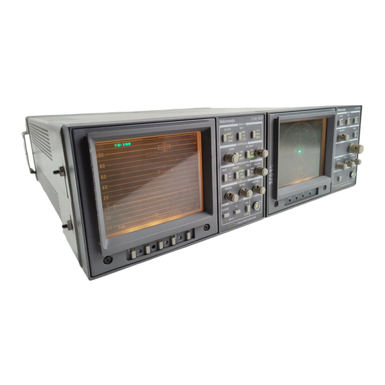
Section 1 Introduction and Specification The TEKTRONIX 1730-Series is an 8-1/2-inch wide by 5-1/4-inch high waveform monitor, weighing approximately 8 pounds. The 1730 (System M, NTSC) and the 1731 (System I, B, etc., PAL, PAL-M), and the 1735 (dual-stan- dard) versions can be powered from an ac source or, with the addition of a field upgrade kit (1700F10), 12 Vdc. -
Page 20: Typical Configurations
1730–Series Introduction An RGB or YRGB Parade display, for camera setup, is accommodated with a shortened sweep. The input of the camera signal and an enable are through the rear-panel REMOTE jack. The choice of 3-step (RGB) or 4-step (YRGB) is made by changing the position of an internal jumper. -
Page 21: Options
Power Cord, with selected power plug option Replacement Cartridge Fuse (correct rating for the power plug option) Replacement Scale Illumination Bulbs (Tektronix Part No. 150-0168-00 or ANSI #73) Optional Accessories There are a number of accessories that can be used with a 1730-Series Waveform Monitor. -
Page 22: Safety Information
1730–Series Introduction Safety Information The 1730-Series is intended to operate from an ac power source that will not apply more than 250 V rms between the supply conductors or between either supply conductor and ground. A protective ground connection by way of the grounding conductor is essential for safe operation (except for those instruments that are operated from a battery supply). -
Page 23: Table 1-1: Vertical Deflection System
1730–Series Introduction Table 1–1: Vertical Deflection System Step Characteristic Requirement Supplemental Information Number Frequency response Flat Flat: 50 kHz to 6 MHz within 2% of Specifications apply for full screen response at 50 kHz. height video input signal, with variable Flat (X5): 50 kHz to 6 MHz within 5% GAIN off. - Page 24 1730–Series Introduction Table 1–1: Vertical Deflection System (Cont.) Step Number Characteristic Requirement Supplemental Information X5 gain accuracy 1 V input signal X5 gain registration 1 major div. of vertical shift from Unmagnified to magnified display baseline. Variable gain range Input signals between 0.8 V and 2 V can be adjusted to 140 IRE (1.0 V) display.
-
Page 25: Table 1-2: Dc Restoration
1730–Series Introduction Table 1–2: DC Restoration Step Characteristic Requirement Supplemental Information Number DC restorer clamp time Back porch Frequency response at 60 Hz Slow: 20% or less Attenuation of 60 Hz on input signal Fast: 90% or greater Blanking level shift with 10% to 90% APL changes from 50% to either 10% APL change or 90% will cause blanking level shift... - Page 26 1730–Series Introduction Table 1–4: Horizontal Deflection System (Cont.) Step Number Characteristic Requirement Supplemental Information 1LINE sweep repetition rate Equal to line rate of applied video or external sync 2LINE sweep repetition rate Equal to half line rate of applied video or external sync Sweep length 2LINE and 2FLD sweep length is...
-
Page 27: Table 1-5: Synchronization
1730–Series Introduction Table 1–4: Horizontal Deflection System (Cont.) Step Number Characteristic Requirement Supplemental Information LINE SELECT Displays the selected line in 1LINE. Displays the selected line first in 2LINE. Intensifies selected line in 2FLD. In 15LINE, displays overlayed lines in 1 or 2LINE, intensifies the selected 15 lines in 2FLD. -
Page 28: Table 1-6: Rgb/Yrgb Mode
1730–Series Introduction Table 1–5: Synchronization (Cont.) Step Number Characteristic Requirement Supplemental Information Remote sync 2.0 to 5.0 V square wave, or 4.0 V Input and enabled through rear-panel Amplitude comp sync REMOTE connector. Input Impedance 1 MW. 30/60 Hz (25/50 Hz) square wave will sync 2FLD Sweep. -
Page 29: Table 1-7: Crt Display
1730–Series Introduction Table 1–7: CRT Display Characteristic Requirement Supplemental Information CRT viewing area 80 X 100 mm Horizontal = 12.5 div Vertical = 170 IRE units (1.19 V) Accelerating potential Nominally 13.75 kV Trace rotation range Greater than 1 from horizontal Total adjustment range is typically 8 Graticule Internal, variable illumination... -
Page 30: Table 1-10: Certifications And Compliances
IEC 801-4 Electrical Fast Transient/Burst Immunity High-quality shielded cables must be used to ensure compliance to the above listed standards. This product complies when installed into any of the following Tektronix instrument enclosures: 1700F00 Standard Cabinet 1700F02 Portable Cabinet 1700F05 Rack Adapter... -
Page 31: Table 1-11: Physical Characteristics
1730–Series Introduction Table 1–10: Certifications and Compliances (Cont.) Category Standards or Description Pollution Degree 4 Pollution that generates persistent conductivity through conductive dust, rain, or snow. Typical outdoor locations. Safety Standards U.S. Nationally Recognized UL1244 Standard for electrical and electronic measuring and test equipment. Testing Laboratory Listing Canadian Certification CAN/CSA C22.2 No. - Page 32 1730–Series Introduction 1–14...
-
Page 33: Section 2 Operating Instructions
Operating Instructions... -
Page 35: Front-Panel Controls And Indicators
Section 2 Operating Instructions These instructions provide information about the front–panel controls, rear– panel connectors, graticules, and an Operator’s Familiarization / Checkout Procedure, along with measurement discussions. Front–Panel Controls and Indicators The front–panel controls and indicators consist of momentary contact push–but- ton switches, variable controls, and backlit switch selections. -
Page 36: Figure 2-1: 1730-Series Front-Panel Control Locations
1730–Series Operating Instructions calibrator. CAL cannot be Stored or Recalled. (Note that MAG and SWEEP are switchable in the Calibrator mode but revert to their previous setting when the mode is exited.) WAVEFORM Tektronix 173X MONITOR INPUT FILTER FLAT CH-A... -
Page 37: Horizontal
1730–Series Operating Instructions CH–A–CH–B Switch that toggles between Channel A and Channel B input. When held, the 1730–Series goes into an AB (BOTH) alternate mode, with the A input on the left and the B input on the right in 2 Line or 2 Field (lines are overlayed in 1 Line sweep). -
Page 38: Display
1730–Series Operating Instructions Toggles between on and off. Operates in conjunction with the SWEEP mode to provide usable sweep rates as follows: 2LINE + MAG = 1 ms/div 2FLD + MAG = 1 full vertical interval 1LINE + MAG = 0.2 ms/div The vertical interval displayed in 2FLD MAG is the one following the selected field trigger;... -
Page 39: Power
1730–Series Operating Instructions 14 INTENSITY Controls display brightness. Power 15 ON Switches between instrument in a powered up state and in standby. Portions of the power supply circuit board still have mains potential on them. A mechanical indicator in the center of the switch shows the status of the POWER switch. WARNING. -
Page 40: Recall Setup
1730–Series Operating Instructions 18 DOWN Decrements the line count (when enabled). Holding the DOWN push button in decrements faster. Holding either button down until the count passes the beginning or end of the field causes the count to shift to the other field. (When LINE SELECT is enabled, holding in both the UP and DOWN push buttons returns the line count to Field 1, Line 19.) Recall Setup... -
Page 41: Miscellaneous
1730–Series Operating Instructions standard (after the slight delay associated with automatic determination of the reference standard). Miscellaneous 21 ROTATE A 270 screwdriver adjustment that aligns the display with the graticule. 22 V CAL A 270 screwdriver adjustment that sets the vertical amplifier gain. Is normally used with the CAL position of the REF switch. -
Page 42: Multi-Pin Connectors
1730–Series Operating Instructions 333-3305-02 WAVEFORM MONITOR FOR LABORATORY DC INPUT USE BY 11 TO 15V QUALIFIED PERSONNEL PIX MON POUR EMPLOI PAR LE PERSONNL DE LABORATOIRE DIE IN DIESEM GERAT ENTSTEHENDE RONTGENSTRAHLUNG IST AUSREICHEND ABGESCHIRMT BESCHLEUNIGUNGSSPANNUNG KLEINER ALS 20kV ACCELERATION VOLTAGE LESS THAN X-RAY EMISSION GENERATED WITHIN THIS INSTRUMENT HAS BEEN SUFFICIENTLY SHIELDED. -
Page 43: Power Input
Performance Check (which should only be performed by qualified service personnel) in Section 5 of this manual. This procedure requires a source of composite video. The TEKTRONIX 1410–Series Television Test Signal Generator (1410 for NTSC, 1411 for PAL, or 1412 for PAL–M) with Sync, Color Bar, and Linearity modules was used in... -
Page 44: Procedure
1730–Series Operating Instructions Procedure This procedure requires only one hook–up to perform. Figure 2-3 shows the required connections. Once the connections are made, continue on to step 1 of the procedure. 1730–SERIES (REAR VIEW) POWER MAINS TERMINATION TERMINATION COLOR BAR SIGNAL LINEARITY SIGNAL 1410–SERIES (REAR VIEW) - Page 45 1730–Series Operating Instructions NOTE. Front–panel screwdriver adjustments: Do not set any of the front–panel screwdriver controls until after the instrument warms up (20 minutes minimum). 3. Initial Front–Panel Setup 1730–Series Waveform Monitor FILTER FLAT INPUT GAIN OFF (no indicators on) POSITION VERTICAL as is DC REST...
-
Page 46: Figure 2-4: Two-Line Color Bar Display In Flat Filter Mode
1730–Series Operating Instructions +0.7 –0.3 2% & 4% K FACTOR Figure 2-4: Two–line color bar display in FLAT filter mode. Adjust the SCALE illumination control for the desired graticule scale brightness. 5. Check the Rotation of the Display Variations in the earth’s magnetic field may make adjustment of the ROTATE control necessary at installation time or whenever the instrument is moved. -
Page 47: Figure 2-5: Checking Vertical Gain Calibration With The 1730-Series Internal Calibrator (Cal) Reference
1730–Series Operating Instructions 12.5% –20 100% –40 NTSC 2% & 4% K FACTOR Figure 2-5: Checking vertical gain calibration with the 1730–Series internal calibrator (CAL) reference. 7. Select Input The AB switch selects the rear–panel Channel A or Channel B inputs. Position the color bar waveform so that the blanking level is at the –40 IRE (0 V) graticule line and the sync pulses are at each end of the graticule. -
Page 48: Figure 2-6: Dual Channel, 2-Line Display Of Color Bar And Linearity Signals
1730–Series Operating Instructions +0.7 –0.3 2% & 4% K FACTOR Figure 2-6: Dual channel, 2–line display of color bar and linearity signals. 8. Select Timing Reference Be sure that SWEEP is still 2LINE. Hold the REF button in until the CAL signal appears. -
Page 49: Figure 2-7: Checking Timing With The Internal Calibrator Signal
1730–Series Operating Instructions 12.5% –20 –40 100% 2% & 4% K FACTOR NTSC 12.5% –20 100% –40 2% & 4% K FACTOR NTSC 12.5% –20 100% –40 NTSC 2% & 4% K FACTOR Figure 2-7: Checking timing with the internal calibrator signal: a) 2–line display. -
Page 50: Figure 2-8: Two-Line Display Of Color Bar Signal With Low Pass Filter On
1730–Series Operating Instructions (PAL) and checking that the maximum excursion of color burst is at approxi- mately the 100 IRE or 1 V graticule line.) Push the button in and hold it until both the VAR and X5 indicators are lit. Rotate the GAIN control and look for a greater than 5X amplitude display at one extreme and a nearly normal amplitude display at the other extreme. -
Page 51: Figure 2-9: Two-Line Display Of Color Bar Signal With Chroma Filter
1730–Series Operating Instructions +0.7 –0.3 2% & 4% K FACTOR Figure 2-9: Two–line display of color bar signal with CHROMA filter. Press the FILTER button once more and look to see that the CHROMA indicator is lit. The signal is now displayed as chrominance only; the luminance component is removed. -
Page 52: Figure 2-11: Two-Line Display With Line Select On
1730–Series Operating Instructions Hold the FILTER button in until both the FLAT and LPASS front–panel indicators are lit. The display now consists of two lines, the first of which has the chrominance removed and the second is unfiltered. See Figure 2-10. Push the FILTER switch and return to FLAT. -
Page 53: Figure 2-12: Two-Field Display With Intensified Line In The First Displayed Field
1730–Series Operating Instructions 12.5% –20 100% –40 NTSC 2% & 4% K FACTOR Figure 2-12: Two–field display with intensified line in the first displayed field. Push the sweep button and observe the 2FLD Sweep with an intensified line at the mid point of one of the fields (see Figure 2-12). This intensified line is located at the line just viewed in the 2–line display. -
Page 54: Figure 2-14: A 1-Line Sweep Rate With 15 Continuous Lines (From Mid Field)
1730–Series Operating Instructions F1:131 12.5% –20 100% –40 NTSC 2% & 4% K FACTOR Figure 2-14: A 1–line sweep rate with 15 continuous lines (from mid field) displayed using LINE SELECT. Push and hold the SWEEP button until the front–panel 1LINE indicator lights. Look for a display of one line, with a readout that shows F1 or F2:131 over 15 (see Figure 2-14). -
Page 55: Graticules
1730–Series Operating Instructions 12. Horizontal Magnifier Select the 2LINE SWEEP and center the horizontal sync on the screen. Press the MAG button and note the magnification of the horizontal sync details. Push SWEEP for 2FLD and MAG for X25 and note that the vertical interval is displayed. -
Page 56: Figure 2-16: Ntsc Graticule
1730–Series Operating Instructions 12.5% –20 100% –40 NTSC 2% & 4% K FACTOR Figure 2-16: NTSC graticule. There are $2 IRE and $4 IRE markings at the center of the –40 IRE line (sync tip) to assist in measuring sync amplitude. This scale is designed to be used with the 2 line and 2 field sweep rates. -
Page 57: Horizontal Scales For Ntsc And Pal Graticules
1730–Series Operating Instructions HAD that exceeds 18 ms, simply measure the bar top in increments by position- ing the bar to the left or right from the leading or trailing edge. Note that when the leading or trailing edge is on the appropriate arrow, the first or last 1 ms is automatically excluded from the measurement.) Pulse–to–bar K–Factor measurements are made using the solid and short dashed lines to the left of the line time distortion structure. -
Page 58: Figure 2-17: Pal Graticule
1730–Series Operating Instructions +0.7 –0.3 2% & 4% K FACTOR Figure 2-17: PAL graticule. The boxed area slightly to the left of center at the 1.0 V level is scaled for 2% and 4% K–Factor ratings for precise tilt measurements. This structure is designed to work with an 8 ms, half–amplitude duration (HAD) bar. -
Page 59: Dual Graticule Vertical Scales
1730–Series Operating Instructions top in increments by positioning the bar to the left or right from the leading or trailing edge. Note that when the leading and trailing edge is on the appropriate arrow, the first or last 1 ms is automatically excluded from the measurement.) Pulse–to–bar K–Factor measurements are made using the solid and short dashed lines to the right of the line time distortion structure. -
Page 60: Preset Front-Panel Measurements
REMOTE connector) selects one of these pre–programmed, front–panel setups. Table 2–1 shows the preset front panels that are stored in memory. When the 1730–Series is used as a direct replacement for the TEKTRONIX 528A Waveform Monitor (which used dc voltage levels as enables), it will be necessary to use a conversion circuit to change these positive voltage levels to apparent ground closures. -
Page 61: Rgb/Yrgb Display
1730–Series Operating Instructions Table 2–1: (Cont.) Preset Front Panels Preset 1 Preset 2 Preset 3 Preset 4 Front–Panel Control (pin 13) (pin 14) (pin 15) (pin 12) HORIZONTAL Magnifier LINE SELECT 15 LINE LINE SELECT (Line) ––– ––– RGB/YRGB Display RGB staircase signals, either 3–... - Page 62 1730–Series Operating Instructions 2–28...
-
Page 63: Service Safety Summary
Service Safety Summary Only qualified personnel should perform service procedures. Read this Service Safety Summary and the General Safety Summary before performing any service procedures. Do Not Service Alone. Do not perform internal service or adjustments of this product unless another person capable of rendering first aid and resuscitation is present. - Page 64 Service Safety Summary S– 2 1730–Series (B070000 & Above)
- Page 65 Warning The following servicing instructions are for use only by qualified personnel. To avoid personnel injury, do not perform any servicing other than that contained in the operating instructions unless you are qualified to do so. Refer to General Safety Summary and Service Safety Summary prior to performing any service.
-
Page 67: Section 3 Installation
Installation... -
Page 69: Packaging
Section 3 Installation This section of the manual provides the information necessary to install the 1730-Series monitor in its operating environment. Information contained here provides electrical and mechanical installation, plus settings for the internal jumpers and descriptions of the available, optional cabinets. Packaging The shipping carton and pads provide protection for the instrument during transit, they should be retained in case subsequent shipment becomes necessary. -
Page 70: Figure 3-1: Plug Jumper Locations And Rgb Compensation Adjustments
1730–Series Installation indicated by a box printed on the etched circuit board. Table NO TAG details these internal jumper selections. Be sure that all operators are aware of changes, to prevent unnecessary trouble reports, if any of these jumpers are placed in the optional position. -
Page 71: Remote Connector
1730–Series Installation Table 3–1: Internal Jumper Selections Jumper Number Name Position Purpose A3J456 RGB/YRGB RGB, 3 step parade (factory pre set) YRGB, 4 step parade A3J504 50/60 Hz 50 Hz line rate (factory set for 1731) 60 Hz line rate (factory set for 1730) (1735 factory set) Jumper in 1 2 position or re... -
Page 72: Figure 3-2: Remote Connector Pin Functions
1730–Series Installation RECALLS REM SYNC ENB 1 LIN/1 FLD RGB ENB STAIRCASE REMOTE PRESETS STORE SYNC IN DISABLE Figure 3-2: REMOTE connector pin functions. Table 3–2: Remote Connector Pin Assignments and Functions Name Function/Description RGB Staircase The RGB Staircase input signal controls the internal sweep ramp to offset the Horizontal in time with the RGB PARADE signal. -
Page 73: 90 Hz (100 Hz) D-2 Trigger
1730–Series Installation Table 3–2: (Cont.) Remote Connector Pin Assignments and Functions Name Function/Description RECALL 2 Recalls the named user defined front-panel settings from non-volatile memory, when pulled low (grounded). If more than one pin ll d l d d) If RECALL 3 (5, 6, 7, or 8) is low, the first pin that went low is the one recalled. -
Page 74: Rgb/Yrgb Parade Display
The displayed signal is the front-panel selected CH A or CH B input. When the 1730-Series Waveform Monitor is substituted for a TEKTRONIX 528 or 528A Waveform Monitor, in some applications the +28 V enable signal used by the 528 must be converted to ground closure (0 Vdc). -
Page 75: Procedure For Setting Rgb Offset
1730–Series Installation Procedure for setting RGB Offset 1. Display any standard television waveform. Do not enable the rear-panel REMOTE connector RGB Enable. 2. Use the 1730-Series HORIZONTAL Position control to align the display with the graticule. 3. Ground the REMOTE connector RGB Enable (pin 2) and apply the camera staircase output to the RGB Staircase input (pin 1). -
Page 76: Mechanical Installation
Table 3–3: Auxiliary Control Pin Assignments Function No Connection. 2-3-4-6 Ground. External Strobe Out for Line Select blanking output. TXD (Transmit Data) 1730 Series to 1720 Series communication line. RXD (Receive Data) 1720 Series to 1730 Series communication line. Mechanical Installation Cabinets All qualification testing for the 1730-Series was performed in a 1700F00 cabinet. -
Page 77: Figure 3-6: 1700F02 Portable Cabinet
The portable cabinet, 1700F02, is shown in Figure 3-6. The 1700F02 has a handle, four feet, a flip-up stand, and is compatible with the TEKTRONIX BP1 battery pack that can be used for a dc power source. The hole sizes and spacing are different from those of the 1700F00. -
Page 78: Cabinetizing
1730–Series Installation Cabinetizing Do not attempt to carry a cabinetized instrument without installing the mounting screws. Without the mounting screws there is nothing to hold the instrument in the cabinet if it is tipped forward. The instrument is secured to the cabinet by two 6-32 Pozidriver screws, located in the upper corners of the rear panel. -
Page 79: Figure 3-8: The 1700F05 Side-By-Side Rack Adapter
1730–Series Installation 18.970 6.875 5.250 17.270 Mounting Holes REAR VIEW Figure 3-8: The 1700F05 side-by-side rack adapter. The rack adapter is adjustable, so the 1730-Series can be more closely aligned with other equipment in the rack. See Figure 3-8. 1700F05 1700F06 Figure 3-9: A 1700-Series instrument mounted in a 1700F05 cabinet with a blank front panel (1700F06) covering the unused side of the cabinet. -
Page 80: Custom Installation
If only one section of the rack adapter is used, a 1700F06 Blank Panel can be inserted in the unused section. See Figure 3-9. The rack adapter and panel are available through your local Tektronix field office or representative. In addition to being able to fill the unused side of the side-by-side rack mount cabinet (1700F05) with a blank front panel, an accessory drawer (1700F07) can be installed in the blank side of the cabinet. -
Page 81: Figure 3-11: Considerations For Custom Installation Of An Instrument
1730–Series Installation For Flush Front Panel: Cut hole the same size as the monitor front molding to allow the monitor front panel to align with the custom panel surface. Requires four 0.156” holes below the 1700F00 cabinet to secure the instrument to the shelf. - Page 82 1730–Series Installation 3–14...
-
Page 83: Section 4 Theory Of Operation
Theory of Operation... -
Page 85: Overview
Section 4 Theory of Operation The material in this section is subdivided into a general description (which is supported by the main block diagram and simplified block diagrams) and detailed circuit descriptions that use the schematic diagrams as illustrations. A thorough understanding of the instrument starts with knowing how the major circuit blocks fit together, which is then followed by an understanding of the individual circuit’s functions. -
Page 86: Block Diagram
1730–Series Theory of Operation Front-panel mode switching is accomplished by a series of push-button switches whose status is being constantly polled by a Microprocessor. In turn, the Microprocessor controls switching functions and circuit gains so that the instrument can perform as a monitor or be used to make specific measurements. The Microprocessor is an 8051 type. - Page 87 1730–Series Theory of Operation X5 Gain is selected at the front panel. The limiter stage that follows prevents overdriving of the Output Amplifier. The conditioned video signal and the Y component of the Readout (from the Microcontroller) are input to the Vertical Output Amplifier to match impedances and normalize gain (approximately 40 V for 8 cm of vertical deflection) in order to voltage drive the CRT vertical deflection plates.
-
Page 88: Crt, Unblanking, And High Voltage
1730–Series Theory of Operation When the RGB Parade display is enabled, the sweep is shortened and offset by the RGB Staircase input signal, which produces three short ramps that are displayed (in sequence) as a normal length sweep. The output of the Mag Amplifier and the X component of the Readout (from the Microcontroller) drive the Horizontal Output Amplifier, which matches impedances and normalizes gain (approximately 100 V for a 10 cm sweep length) in order to voltage drive the CRT horizontal deflection plates. -
Page 89: Input Amplifiers
1730–Series Theory of Operation Input Amplifiers The rear-panel Channel A and B inputs are high-impedance bridging loop- through inputs compensated for use in 75W systems. Each amplifier has its own DC Restorer that is controlled by the front-panel restorer switch. Restorers are either both on or off;... -
Page 90: External Sync Input And Source Switch
1730–Series Theory of Operation External Sync Input and The external sync signal from the rear-panel EXT REF loop-through is buffered Source Switch by an operational amplifier consisting of U795A and B. It has a gain of –1, which is determined by the combination of input resistor (R ) R997 and feedback resistor (R ) R898. -
Page 91: Filter Selection
1730–Series Theory of Operation CLAMP R992 COMP R993 SYNC VIDEO (SOURCE SWITCH) U892B Q992 & U892C Figure 4-2: Simplified block diagram of the Sync Stripper. An inverting amplifier, U892B, is the second amplifier stage. It provides negative-going sync and cleans up any remaining noise or active video on the signal. -
Page 92: Calibrator
1730–Series Theory of Operation and R885 generates a pulse through Q764. Q765 inverts the blanking pulse, which is input to the blanking circuitry on Diagram 4. Calibrator The Calibrator is a common base amplifier, Q587, that is driven by a 100 kHz square wave from the Microprocessor (Diagram 5). -
Page 93: Gain Cell Amplifier
1730–Series Theory of Operation front-panel GAIN control alters the dc level on pin 10 through an analog switch, U585B. The switch is closed only when Variable is selected. The current flowing out of pin 6 drives the Gain Cell Amplifier, while the current flowing out of pin 12 drives into a collector load, R480. -
Page 94: Vertical Output Amplifier
1730–Series Theory of Operation Figure 4-3: Simplified illustration of the Bridge limiter circuit. When the bridge unbalances the current through the diodes changes, with more current flowing into the load through either CR3 (positive excursion) or CR4 (negative excursion), which turns the diode on harder. At the same time current flowing through the complementary input diode CR1 (positive excursion) or CR2 (negative excursion) is reduced and the diode starts to turn it off. -
Page 95: Pix Monitor
1730–Series Theory of Operation linearity and reduce the thermal distortions introduced by Q383. In addition, negative feedback increases the input impedance. A series compensation network consisting of R384 and C384 provides improved bandwidth and stability. The combination of Q385 and Q387 form a shunt-feedback amplifier, identical to Q383 and Q382. -
Page 96: Horizontal Sync Generator
1730–Series Theory of Operation LINE RATE COMPARATOR SYNC H SYNC Figure 4-4: Simplified representation of the AFC phase-lock loop. Horizontal Sync Generator The Comp Sync, from the Sync Separator on Diagram 1, drives the timing input to U735. U735 is a registered 16-input gate array that outputs line rate enables and SYNC. -
Page 97: Vertical Sync Generator
1730–Series Theory of Operation The DC Restorer back porch pulse is generated by a one-shot, U844A. When SYNC occurs, U844A is cleared. The next line rate pulse output from U844B will start the one-shot, whose pulse width is determined by C848 and R849. The output pulse from Q99, an emitter follower, is time coincident with the back porch of the input sync signal. - Page 98 1730–Series Theory of Operation COMP SYNC H SYNC LIN SEL EN LISEL LIN STRB PIXSTRB COMP SYNC H SYNC (HIGH) LIN SEL EN LISEL LIN STRB PIXSTRB (LOW) H LIN SEL EN Figure 4-5: Elements for line select timing: a) Line select off. b) 2-field line select.
-
Page 99: Figure 4-6: Relative Line Select Elements For The 2-Line Display
1730–Series Theory of Operation COMP SYNC H SYNC 2H SWEEP (HIGH) LIN SEL EN LISEL LIN STRB PIXSTRB (LOW) H LIN SEL EN DISPLAYED LINES Figure 4-6: Relative line select elements for the 2-line display. In addition, U535 decodes instructions for selecting either the applied sync (CAL high) or the Calibrator (CAL low) for the source of line rate sync (H TRIG). -
Page 100: Sweep Generators And Horiz Output Diagram
1730–Series Theory of Operation COMP SYNC H SYNC (LOW) LIN SEL EN (HIGH) 2H SWEEP LISEL LIN STRB PIXSTRB H LIN SEL EN DISPLAYED LINE Figure 4-7: Relative line select timing elements for the 1-line display. Sweep Generators and Horiz Output Diagram 4 Sweep Generator U552B (Line Rate Sweep Generator) and U552A (Field Rate Sweep Generator) -
Page 101: Magnifier Amplifier
1730–Series Theory of Operation U541 PIN 3 H TRIGGER U541 PIN 5 (Q) 1-LINE SWEEP WITH SYNC U541 PIN 5 (Q) 2-LINE SWEEP WITH SYNC U552 PIN 6 1-LINE SWEEP U552 PIN 6 2-LINE SWEEP U741 PIN 6 Figure 4-8: Timing signals for 1-line and 2-line sweep. If there is no H or V Trigger, the output of the running Sweep Generator is self retriggered. -
Page 102: Horizontal Output Amplifier
1730–Series Theory of Operation staircase signal, when RGB/YRGB operation is selected). The length of the sweep, in RGB mode, is set by jumper J456 to accommodate either three- or four-step sweeps (for RGB and YRGB modes). U465A and U465B are comparators used to sense when the output of the Magnifier and Position Amplifier have driven the CRT beam to the edge of the CRT screen. -
Page 103: Table 4-1: Control Line Functions
1730–Series Theory of Operation (X5, BLANK DOT, LINSEL, and 2H SWP PH). Pin 24 is the external communications enable that controls the Auxiliary interface. Pins 13, 14, and 15 input horizontal (line) sync and vertical (field) sync, to decipher line select data and real-time switching functions (A/B and Low Pass/ Flat switching). -
Page 104: Novram
1730–Series Theory of Operation Table 4–1: (Cont.)Control Line Functions Signal Line State Result LIN/FLD High 1 or 2 Line display. (U532) LIN/FLD 2 Field display. (U532) TWO/ONE High 2 Field or 2 Line display. (U532) TWO/ONE 1 Line (no single field display possible). (U532) High Enables Horizontal Magnifier. -
Page 105: Switch Control
1730–Series Theory of Operation U726 is the power down detection circuit. It detects the loss of instrument power in time for the NOVRAM (U725) to execute a save operation. When the +5 V supply drops a few hundred millivolts, pin 7 is pulled low, which pulls the STR for U725 down, causing it to Store its current status. -
Page 106: Focus Control
1730–Series Theory of Operation Control Circuit Diagram 6 Blanking signals, for video and readout, are input to an intensity switching matrix along with a dc voltage level set by the front-panel INTENS control. Focus level, for the CRT focus anode, is set by regulating the current through a transistor current source. -
Page 107: Trace Rotation
1730–Series Theory of Operation BLANK 2-FIELD SWEEP BLANK 2 SELECTED LINE (LOW) ROEN INTENSIFIED LINE A3Q346 & A3Q347 Z-AXIS OUT (ANALOG) FRONT PANEL INTENSITY LEVEL 2-LINE SWEEP BLANK BLANK 2 READOUT ELEMENTS READOUT ROEN TIME READOUT INTENS- INTENS SETTING Z-AXIS OUT CONTROL (ANALOG) SETTING... -
Page 108: Front Panel Diagram
1730–Series Theory of Operation Front Panel Diagram 7 The front-panel indicators are driven from Microcontroller light driver register and LED drivers from Diagram 5. The front-panel switches are momentary closure (with some hold for additional function capabilities) that are monitored by the Microprocessor, which is also on the Microcontroller (Diagram 5). -
Page 109: Low Voltage Power Supply Diagram
1730–Series Theory of Operation Low Voltage Power Supply Diagram 8 The Low Voltage Power Supply converts the mains line voltage (90–250 VAC) to supply the power requirements of the instrument. The voltages supplied by the Low Voltage Power Supply are +40 V, "15 V, and +5 V. The Low Voltage Power Supply is called a Flyback Switcher. -
Page 110: Pulse Width Modulator
1730–Series Theory of Operation Pulse Width Modulator U5 is a current-mode Pulse Width Modulator (PWM). A current-mode PWM uses two feedback loops. The inner current-feedback loop directly controls the switcher mosfet peak current. The outer voltage-feedback loop programs the inner loop peak current trip point. U5 pin 2 is the inverting input of an internal op-amp. -
Page 111: Output Filters
1730–Series Theory of Operation Output Filters The three output windings supply four output voltages. Each output is rectified by a single diode and filtered by an LC pi filter. Error Amplifier The Error Amplifier regulates the +5 V output by feeding an error signal to the Pulse Width Modulator. -
Page 112: High Voltage Power Supply Diagram
1730–Series Theory of Operation High Voltage Power Supply Diagram 9 The High Voltage Power Supply generates the heater, cathode, control grid, focus anode, and post accelerating potentials required to display the outputs of the Vertical and Horizontal Output Amplifiers. HV Osc and Error Amp The High Voltage Power Supply is generated by a sine-wave oscillator and step-up transformer. -
Page 113: Focus Amplifier
1730–Series Theory of Operation Focus Amplifier Q1 and Q2 form an operational amplifier that sets the voltage at the bottom of the focus divider. The front-panel FOCUS pot determines the voltage at the bottom of the focus divider. The Center Focus control, R11, is set for optimum beam focus, as viewed on the CRT, with the front-panel FOCUS control set to mid range. -
Page 114: Figure 4-10: Pinout Of The Crt Socket
1730–Series Theory of Operation The pinout for the CRT is shown in Figure 4–3. Description Filament (f) Cathode (k) GRID (g1) FOCUS (g3) ASTIG (g4) GEOM (g5) VERT PLATE (y2) VERT PLATE (y1) HORIZ PLATE (x2) 1st ANODE (g2) HORIZ PLATE (x1) Filament (f) Figure 4-10: Pinout of the CRT Socket 4–30... -
Page 115: Section 5 Checks And Adjustments
Checks and Adjustments... -
Page 117: Recommended Equipment List
Time Base: 10 ns/div to 5 ms/div sweep speeds, triggering to 5 MHz. For example: a TEKTRONIX TAS 465 Oscilloscope. Also 10X probes, P6106 (Tektronix Part No. 010–6106–03), and a 1X probe, P6101 (Tektronix Part No. 010–6101–03). 2. Television Signal Generator... - Page 118 2T bar, and modulated pulse signals, and field square wave signal), multiburst signal, and black burst signal. For example: NTSC TEKTRONIX 1410 with Option AA and Option AB (modified SPG2 and TSG7), TSG3, TSG5, and TSG6. PAL TEKTRONIX 1411 with Option AA and Option AB (modified SPG12 and TSG11), TSG13, TSG15, and TSG16.
-
Page 119: Auxiliary Equipment
1730–Series Checks and Adjustments For example: TEKTRONIX DM504A in a TM500 Series Power Module. 6. Frequency Counter Range, 100 kHz to 5 MHz; accuracy, ±0.001%. For example: TEKTRONIX DC503A in a TM500 Series Power Module. 7. Video Amplitude Calibrator Signal, adjustable square wave 0.0 to 999.9 mV p-p with a resolution of 0.1 mV and an accuracy of 0.05%;... - Page 120 Engineering Part No. A56T75B. 14. 75Ω Terminators Three required, one should be a feed-through type. For example: End-line, 75Ω terminator (Tektronix Part No. 011–0102–00) and a feed-through 75Ω terminator (Tektronix Part No. 011–0103–02). 15. 75Ω Coaxial Cable Three required. For example: 42-inch RG59U (Tektronix Part No. 012–0159–00).
-
Page 121: Figure 5-1: Remote Connector For Rgb
1730–Series Checks and Adjustments 19. Precision 50W Coaxial Cable For example: Tektronix Part No. 012–0482–00 (used with the SG503). 20. 50W-to-75W Minimum Loss Attenuator For example: Tektronix Part No. 011–0057–00. 21. Parade Display Test Connector A 15-pin sub-miniature D-type connector (for example: Tektronix Part No. -
Page 122: Figure 5-2: Remote Connector For 90/100 Triggering
1730–Series Checks and Adjustments Remote 90/100HZ SYNC enable trigger enable ground Factory preset #1 Remote SYNC input Figure 5-2: Remote connector for 90/100 triggering. 5–6... -
Page 123: Performance Check
1730–Series Checks and Adjustments Performance Check The Short-Form Procedure is intended for those who are familiar with the complete Performance Check procedure. Step numbers and sub-step designa- tions correlate directly to the steps in the Performance Check Procedure; this makes it possible to use the Short-Form Procedure as a table of contents. Short-form Procedure 1. - Page 124 1730–Series Checks and Adjustments e. Check 2LINE SWEEP linearity. h. Check 1LINE SWEEP accuracy and linearity. Check 1 ms SWEEP accuracy and linearity. q. Check 0.2 ms SWEEP accuracy and linearity. 7. RGB/YRGB Parade Display d. Check shortened sweep length. e.
- Page 125 1730–Series Checks and Adjustments s. Check DC RESTORER with loss of burst. 13. Flat Response d. Check CH–B flat response. g. Check CH–B X5 flat response. Check CH–A X5 flat response. Check CH–A flat response. 14. PIX MON OUT Frequency Response d.
-
Page 126: Performance Check Procedure
1730–Series Checks and Adjustments Performance Check Procedure 1. Preliminary Setup a. Set up the 1730–Series front-panel controls as shown in Table 5–1. Table 5–1. Preliminary Control Settings POWER INTENSITY Set to preference FOCUS SCALE VERTICAL Position Set later HORIZONTAL Position Set later FILTER FLAT... - Page 127 1730–Series Checks and Adjustments d. Return the autotransformer to 110 or 220 Volts. 3. Check Calibrator Frequency REQUIREMENT – Frequency 100 kHz ±100 Hz, Synchronizes 1LINE and 2LINE SWEEP (free runs in 2FLD). a. Connect a X10 probe from the frequency counter to the blue CRT lead on the 1730–Series Main circuit board.
- Page 128 1730–Series Checks and Adjustments 5. Sweep Operation REQUIREMENT – Check that the correct sweep rate can be selected. Check that some part of the blanking interval is displayed when magnifying the centered 2LINE and 2FLD sweeps. a. Display INPUT A with nothing connected. b.
-
Page 129: Figure 5-3: Ten Full Cycles Of Calibrator Signal Between Timing Marks
1730–Series Checks and Adjustments 12.5% Shaded area represents the distance between 10 ms and 110 ms timing marks. –20 100% –40 NTSC 2% & 4% K FACTOR Figure 5-3: Ten full cycles of calibrator signal between timing marks. d. CHECK – for 10 full cycles of calibrator signal in the 10 center major graticule divisions, ±2% (1 minor division). - Page 130 1730–Series Checks and Adjustments m. Adjust the multiburst Frequency for a 5 MHz sine wave as measured on the digital counter. n. Select the 1730–Series INT REF and 1 LINE SWEEP. Turn on the MAG and VAR GAIN. Adjust the VAR GAIN control for approximately six vertical divisions of display.
- Page 131 1730–Series Checks and Adjustments shows the location of R856. Connect a 0 to +10 V, 2 kHz square wave to the bnc connector of the Parade Display Test Connector, as shown in the equipment list. h. CHECK – that 7.6 to 10.4 divisions of deflection have been added by the square wave.
-
Page 132: Figure 5-4: Equipment Hook–Up For Checking Vertical Gain
1730–Series Checks and Adjustments video amplitude with the VARIABLE gain. Less than 1 major division shift from baseline between unmagnified and magnified signal. a. Connect the Video Amplitude Calibrator (VAC) to the CH–A INPUT. Connect the linearity output of the television test signal generator to the CH–B INPUT. - Page 133 1730–Series Checks and Adjustments h. CHECK – Turn on the 1730–Series VARIABLE gain (X5 is off) and adjust the VARIABLE control for a sync pulse amplitude greater than 100 IRE (720 mV for PAL). CHECK – Adjust the 1730–Series VARIABLE control for a display amplitude of 140 IRE (1.0 V for PAL) or less.
-
Page 134: Figure 5-5: Checking Pix Mon Out Signal Amplitude
1730–Series Checks and Adjustments Composite Sync from the television test signal generator to the 1730–Series EXT REF and terminate remaining side of the loop–through input. See Fig. 5-5. 1730–SERIES (REAR VIEW) TERMINATION Connect at part i TERMINATION of step. TERMINATION 1410–SERIES (REAR VIEW) Figure 5-5: Checking PIX MON OUT signal amplitude. - Page 135 1730–Series Checks and Adjustments CHECK – that the amplitude of the color bar is within 0.95 to 1.05 V from sync tip to the 100% peak white bar, as displayed on the test oscilloscope. Turn OFF the 1730–Series LINE SELECT. k.
-
Page 136: Figure 5-6: Initial Equipment Setup To Check Flat Response
1730–Series Checks and Adjustments o. Switch linearity signal APL between 50% and 10% and between 50% and 90%. p. CHECK – that the signal blanking level moves less than 1 IRE (7 mV). q. Connect the multiburst signal to the CH–A INPUT and terminate the remaining side of the loop–through input. - Page 137 1730–Series Checks and Adjustments a. Connect a 50Ω precision cable and 50 to 75Ω minimum loss pad from the leveled sine wave to the CH–A input. Teminate the loop–through in 75Ω. b. Select EXT REF. c. Set the leveled sine wave generator to 50 kHz (reference frequency) and set the output amplitude for a 100 IRE (0.7 V) display amplitude.
- Page 138 Set the 1730–Series GAIN to NORMAL and REF to EXT. g. Set the sine wave generator to 50 kHz (reference frequency) and adjust the generator amplitude for a 1 Volt display on the 1730 Series. h. Set the following controls on the Vertical Input: Volts/Div.
- Page 139 1730–Series Checks and Adjustments Select the field square wave signal. Display the signal with the 2FLD SWEEP. g. CHECK – for less than 1% tilt across the high APL portion of the display. h. Set the 1730–Series VERTICAL to X5 gain. Select 2LINE SWEEP and SWEEP MAG ON.
- Page 140 1730–Series Checks and Adjustments e. CHECK – that the amplitude of the linearity signal, in LPASS, is within ±1% of the amplitude of the display in the FLAT mode. 18. Check Chroma Filter Response REQUIREMENT – Response at 3.58 MHz (4.43 MHz for PAL) does not vary between FLAT and CHROMA by more than 1%.
- Page 141 1730–Series Checks and Adjustments c. Select Demod/TG on the spectrum analyzer. Turn on the tracking generator and set the tracking generator fixed level to 0.00 dBm. d. Set the spectrum analyzer Span/Div to 1 MHz and the Resolution Bandwidth to 30 kHz. e.
- Page 142 1730–Series Checks and Adjustments v. Check that the 1730–Series inputs are not terminated and that there is no signal applied. Connect the Device Under Test connector on the RF Bridge to the PIX MON OUT connector. w. CHECK – that the return loss of the PIX MON OUT is better than 30 dB (15.8 mV), from 50 kHz to 6 MHz.
-
Page 143: Adjustment Procedure
1730–Series Checks and Adjustments Adjustment Procedure The Adjustment Procedure covers only adjustments. Checks, other than those that must be made to ensure a step is completed, are in the Performance Check Procedure. There are actually two Adjustment Procedures, the short–form version is provided for those familiar with the adjustments, while the longer (more detailed) procedure is provided for those who need it.Allow 20 minutes of warm–up time, at normal room temperature (approximately 25°... -
Page 144: Standard Adjustment Procedure
1730–Series Checks and Adjustments 17. Adjust Channel–B Input Compensation (C696) 18. Adjust X5 Gain HF Response (C372) 19. Adjust Video Out Response (C694) 20. Adjust Low Pass Filter (C777 and C775) 21. Adjust Chroma Filter (1730–R683, C683, and C783; 1731–R680, C778, and C784;... -
Page 145: Figure 5-7: Adjustment Locations For The Main And Power Supply Boards
1730–Series Checks and Adjustments É É É É É É É É É É É É É É É É É É É É É É É É É É É É É É É É É É FOCUS É É É É É É É É É É É É É É É É É CAUTION É... - Page 146 1730–Series Checks and Adjustments A1 POWER SUPPLY BOARD 1. Adjust +5 V Connect the DMM negative lead to TP1 (GND) and the positive lead to W1 (+5V). ADJUST – R99 (+5V ADJ) for +5.0 V "0.5V. 2. Adjust CRT Bias a.
-
Page 147: Figure 5-8: Segment Of The Main Board, Showing The Test Points And Adjustment Locations For The +11.8 V Supplies
1730–Series Checks and Adjustments FRONT R167 R168 U164 U172 A3 MAIN BD –11.8 V +11.8 V TEST POINT TEST POINT Figure 5-8: Segment of the Main board, showing the test points and adjustment locations for the +11.8 V supplies. b. ADJUST – R167 (–11.8 V ADJ) for –11.78 to –11.82 volts. c. -
Page 148: Figure 5-9: Equipment Setup To Adjust 0.2 Ms Timing
1730–Series Checks and Adjustments b. Loop-through connect the multiburst output from the 1410-Series generator to the CH–A INPUT of the 1730-Series and the Digital Counter. See Fig. 5-9. DIGITAL COUNTER 1730-SERIES (REAR VIEW) MULTIBURST SIGNAL 1410-SERIES (REAR VIEW) Figure 5-9: Equipment setup to adjust 0.2 ms timing. c. - Page 149 1730–Series Checks and Adjustments h. ADJUST – R553 for 10 cycles of subcarrier over 10 divisions ±1 minor division. Recheck multiburst generator frequency by switching it back to Continuous. Disconnect the cable that goes to the Digital Counter and terminate the open side of the CH–A input with a 75W end-line terminator.
- Page 150 1730–Series Checks and Adjustments ADJUST – R856 (RGB Offset) to center the display at mid screen. 11. Adjust RGB Compensation a. Remove the color bar signal from the CH–A INPUT. b. Input a 10 V, 2 kHz square-wave signal, from the function generator, to pin 1 (with pin 2 still grounded) of the 1730-Series rear-panel REMOTE connector.
-
Page 151: Figure 5-10: Equipment Setup For Adjusting The Calibrator Amplitude
1730–Series Checks and Adjustments 1730-SERIES (REAR VIEW) DO NOT TERMINATE Figure 5-10: Equipment setup for adjusting the calibrator amplitude. b. Set the VAC for 999.9 mV. c. Adjust the 1730-Series front-panel V CAL so that the VAC signal is displayed as exactly 1 V p-to-p (140 IRE on the NTSC graticule) on the CRT graticule. -
Page 152: Figure 5-11: Equipment Setup For Adjusting Channel A Input Compensation
1730–Series Checks and Adjustments c. Select X5 GAIN. d. ADJUST – R274 (X5 Mag) to reposition blanking level to the baseline. e. Select GAIN off and repeat parts b, c, and d until there is no baseline shift when switching between off and X5 GAIN. 16. -
Page 153: Figure 5-12: Adjusting For Best Flat Response
1730–Series Checks and Adjustments b. Set multiburst generator to Sweep, High Range, Composite, Markers, and Full Amplitude. c. Set the 1730-Series SWEEP to 2FLD and EXT REF. d. Set the test oscilloscope Vertical Volts/Div to 100 mV. e. ADJUST – C195 (CH–A Comp.) for flat response at 6 MHz. See Fig. 5-12. - Page 154 1730–Series Checks and Adjustments Connect the output of the leveled sine wave generator to the CH–A and CH–B INPUTS, using a precision 50W cable, a 50–75W minimum loss attenuator, a 75W feed through attenuator, and the dual input coupler. Set the leveled sine wave generator Frequency to 50 kHz and adjust its Amplitude for a 100 IRE (NTSC or PAL–M) or 700 mV (PAL) output as displayed on the 1730-Series.
-
Page 155: Figure 5-13: Using The High-Range Multiburst Signal To Set Flatness
1730–Series Checks and Adjustments Set the sine wave generator Frequency to 3.58 MHz (NTSC and PAL–M) or 4.43 MHz (PAL). For dual-standard waveform monitors, make the NTSC adjustment only for this step. g. ADJUST – C372 (X5 Comp) for an amplitude of 100 IRE (NTSC and PAL–M) or 700 mV (PAL). - Page 156 1730–Series Checks and Adjustments a. Set the 1730–Series SWEEP rate to 2LINE. b. Turn off DC REST. c. Connect color bar signal to the CH–A INPUT. d. Select INPUT A and LPASS FILTER. e. Turn on HORIZONTAL MAG and X5 VERTICAL GAIN. ADJUST –...
- Page 157 1730–Series Checks and Adjustments employed. For dual-standard waveform monitors, make both the NTSC and PAL adjustments, using the appropriate signal generator. g. ADJUST – C683 (3.58 NTSC and PAL–M) or C778 (4.43 PAL) for the squarest envelope (minimum burst envelope decay time). It may be necessary to readjust C783 (NTSC or PAL–M) or C784 (PAL) for maximum amplitude.
- Page 158 1730–Series Checks and Adjustments e. ADJUST — A3R245 (LS Focus) for the optimum display definition. ADJUST – the front panel READOUT screwdriover adjustment to match the readout intensity to the Display Intensity. g. Turn LINE SELECT Off. End of Adjustment Procedure. 5–42...
-
Page 159: Section 6 Maintenance
Maintenance... -
Page 161: Preventive Maintenance
Section 6 Maintenance This section contains instructions for preventive maintenance, general trouble- shooting, Serial Port and LED Driver diagnostics, and corrective maintenance. If the instrument does not function properly, troubleshooting and corrective measures should be taken immediately to circumvent additional problems. Preventive Maintenance Preventive maintenance consists of cleaning, visual inspection, performance checking, and, if needed, readjustment. -
Page 162: Visual Inspection
1730–Series Maintenance (high–velocity air can damage some parts). Hardened dirt or grease may be removed with a cotton–tipped applicator dampened with a solution of mild detergent and water. Abrasive cleaners should not be used. If the circuit board assemblies must be removed for cleaning, follow the instructions for removal/re- placement under the heading of Corrective Maintenance. -
Page 163: Performance Checks And Readjustments
1730–Series Maintenance Table 6–1: (Cont.)Static Susceptibility Relative Susceptibility Levels Voltage 900 V LOW POWER SCHOTT- KY TTL 1200 V Observe the following precautions to avoid damage: 1. Minimize handling of static–sensitive components. 2. Transport and store static–sensitive components or assemblies in their original containers, on a metal rail, or on conductive foam. -
Page 164: Foldout Pages
1730–Series Maintenance The procedural information that appears as General Troubleshooting Techniques should be familiar to most technicians; however, a quick review may save some time and reduce “wheel spinning.” Foldout Pages The foldout pages at the back of the manual contain information that is useful in troubleshooting the instrument. -
Page 165: Parts Lists
1730–Series Maintenance A1 Power Supply Board A3 Main Board A2 Front Panel Board Figure 6-1: Circuit board assembly locations. Adjustment Locations. Section 5 has illustrations that have the adjustments and test points called out as calibration and troubleshooting aids. Parts Lists There are two separate parts lists in this manual. -
Page 166: Major Assembly Interconnection
1730–Series Maintenance exploded view drawing comprise Section 10 of this manual. Standard Accesso- ries, which are also included in the parts list, are also in the exploded view drawing. Major Assembly Signals and power supply voltages are passed through the instrument with a Interconnection system of interconnecting cables. -
Page 167: General Troubleshooting Techniques
1. Ensure that the malfunction exists in the instrument. This is done by making sure that the instrument is operating as intended by Tektronix (see Operating Instructions in Section 2), and by checking that a malfunction has not occurred up stream from the waveform monitor. -
Page 168: Specific Troubleshooting Techniques
1730–Series Maintenance CAUTION. Removing Components: Always remove the assembly from the instrument prior to attempting to replace a soldered in component. See Corrective Maintenance for the correct procedure. Specific Troubleshooting Techniques The 1730–Series Waveform Monitor has two areas where ordinary troubleshoot- ing techniques do not apply. -
Page 169: Introduction
1730–Series Maintenance H Clip Lead – to short across a component H High Voltage Probe, w1 GW input resistance Introduction The Troubleshooting Procedure for the Power Supply (Assembly A1) is split into two sections, the Low Volts and High Volts Supplies. Start the procedure by determining which section of the power supply the problem is in. - Page 170 1730–Series Maintenance Table 6–3: (Cont.)Low Volts Supply Voltages Test Point Voltage Range W3 – (–15 V) –14.0 to –16.0 V W2 – (+40 V) +39.0 to +41.0 V NOTE. Low Volts Supply Power Connection: The Low Volts power supply troubleshooting is performed without applying ac power.
-
Page 171: Table 6-4: Control Circuit Test Points
1730–Series Maintenance than 20 mA. Excessive current draw can be caused by CR11 or U2 (High Volts power supply). b. Connect the negative output from the 20 V DC Power Supply to TP1. Connect the positive output to W2 (+40 V). The circuit should draw less than 20 mA. -
Page 172: High Volts Supply
1730–Series Maintenance c. Remove the clip lead from across C47. 5. Error Amplifier Check a. Connect the negative output from the variable DC power supply to TP1. Connect the positive output to W1 (+5 V). b. Connect the negative output of another variable DC power supply to TP1. -
Page 173: Table 6-6: High Voltage Oscillator Test Points
1730–Series Maintenance c. Using the digital multimeter, measure the voltage between TP1 and the collector of Q1. It should be approximately –140 V. d. Reconnect the lifted end of R24. 3. Z-Axis Amplifier Check a. Unsolder and lift one end of R8. b. -
Page 174: Serial Port And Led Driver Diagnostics
1730–Series Maintenance Table 6–6: (Cont.)High Voltage Oscillator Test Points Circuit Location Voltage U2, pin 2 Approximately +4.8 V U2, pin 6 +4 to +11 V CR9, cathode Approximately +100 V 6. CRT Voltage Check NOTE. High Voltage Probe: This check requires a high voltage probe having an input resistance of 1 GW or more. -
Page 175: Corrective Maintenance
The rosin residue, if left alone, does not exhibit these corrosive properties. Obtaining Replacement Replacement parts are available through the local Tektronix field office or Parts representative. However, many common electronic parts are available through local sources. Using a local source, where possible, will eliminate shipping delays. -
Page 176: Mechanical Disassembly/Assembly
If a part has been replaced with a new or improved part, the new part will be shipped (if it is a direct replacement). If not directly replaceable the local Tektronix field office or representative will contact the customer concerning any changes. After any repair, circuit readjustment may be required. -
Page 177: Graticule Light Removal And Replacement
CAUTION. Bulb Removal: Needle-nosed pliers are not recommended. Replacement bulbs are supplied with this instrument as Standard Accessories. Additional bulbs can be purchased from Tektronix (see Replaceable Electrical Parts list) or from local electronics distribution sources. Procedure 1. Remove the bezel according to the preceding instructions. - Page 178 1730–Series Maintenance 3. To install a bulb, hold it with the tweezers as described in step 2, position it in front of the socket, and push the bulb with your finger until it snaps into place. 4. Replace the bezel. CRT Removal 1.
-
Page 179: Removing The Rear Panel
1730–Series Maintenance 6. Replace the trace rotation connector (J225, Main board), and snap the anode lead onto the anode connector on the side of the CRT. 7. Wipe the faceplate of the CRT to remove fingerprints, then replace the bezel. If the fit is too tight to allow the bezel to go into position, or if the CRT has a loose fit after the bezel is completely tightened down, then the rear CRT support must be repositioned. - Page 180 1730–Series Maintenance 3. Remove the board by slipping it through the front–panel opening. 6–20...
-
Page 181: Removing The Main Board
1730–Series Maintenance 4. To access the Front Panel board components: a. Remove the knobs from the front. b. Remove the four screws from the rear. c. The board should now separate from the front panel making the components accessible. 5. To re–assemble, reverse the procedure. To Remove Front Panel Assembly... -
Page 182: Removing The Power Supply Board
1730–Series Maintenance 4. Remove the eight screws that are holding the board in place. See Fig. 6-6 for their locations. J154 J107 FRONT J932 Remove these screws to remove this board Figure 6-6: Screws holding the Main circuit board (A3) in place. 5. -
Page 183: Repackaging
Repackaging Identification Tag If the instrument is to be shipped to a Tektronix Service Center for service or repair, attach a tag to the instrument showing: 1. Owner (with complete address) and the name of the person at your firm that can be contacted. -
Page 184: Figure 6-8: Repackaging A 1730–Series Instrument
1730–Series Maintenance Figure 6-8: Repackaging a 1730–Series instrument. 6–24... -
Page 185: Section 7 Options
Options... -
Page 187: Crt Options
There are two optional cabinets and a dual rack adapter available for the installation of these instruments. Only a brief description is provided here, for more information contact a Tektronix field office or distributor. Plain Cabinet (1700F00) This is a plain, silver–grey cabinet that is designed for permanent mounting. -
Page 188: Carrying Case (1700F02)
Any of these items can be ordered with the 1730–Series instrument. In addition, these items are available, along with accessory items listed in this manual, from your nearest Tektronix field office or distributor. Be sure to include both the name and number of any Field Upgrade Kits ordered. -
Page 189: Section 8 Replaceable Electrical Parts
Replaceable Electrical Parts... -
Page 191: Parts Ordering Information
1730-Series. Use this list to identify and order replacement parts. There is a separate Replaceable Electrical Parts list for each instrument. Parts Ordering Information Replacement parts are available from or through your local Tektronix, Inc., Field Office or representative. Changes to Tektronix instruments are sometimes made to accommodate improved components as they become available and to give you the benefit of the latest circuit improvements. -
Page 192: Column Descriptions
Chassis-mounted parts and cable assemblies have no assembly number prefix and are located at the end of the electrical parts list. Tektronix Part No. Indicates part number to be used when ordering replacement part from (Column 2) Tektronix. -
Page 193: Cross Index – Mfr. Code Number To Manufacturer
1730–Series Replaceable Electrical Parts Cross Index – Mfr. Code Number To Manufacturer Mfr. Code. Manufacturer Address City, State, Zip Code 00779 AMP INC 2800 FULLING MILL HARRISBURG PA 17105 PO BOX 3608 00853 SANGAMO WESTON INC SANGAMO RD PICKENS SC 29671–9716 COMPONENTS DIV PO BOX 128 01121... - Page 194 76493 BELL INDUSTRIES INC 19070 REYES AVE COMPTON CA 90224–5825 JW MILLER DIV PO BOX 5825 80009 TEKTRONIX INC 14150 SW KARL BRAUN DR BEAVERTON OR 97077–0001 PO BOX 500 84411 AMERICAN SHIZUKI CORP 301 WEST O ST OGALLALA NE 69153–1844...
- Page 195 1730–Series Replaceable Electrical Parts Mfr. Code. Manufacturer Address City, State, Zip Code BLDG 17–11 TK1573 WILHELM WESTERMAN PO BOX 2345 6800 MANNHEIM 1 WEST GERMANY AUGUSTA–ANLAGE 56 TK1913 WIMA 2269 SAW MILL RIVER ROAD ELMSFORD NY 10523 THE INTER–TECHNICAL GROUP IND PO BOX 127 8–5...
- Page 196 1730–Series Replaceable Electrical Parts Replaceable Electrical Parts Component Tektronix Serial / Assembly Number Mfr. Mfr. Part Number Part Number Effective Discontinued Code Number Name & Description 671–2890–11 B079210 CIRCUIT BD ASSY:POWER SUPPLY (1730 ONLY) 80009 671289010 671–2890–11 B079467 CIRCUIT BD ASSY:POWER SUPPLY (1731 ONLY)
- Page 197 1730–Series Replaceable Electrical Parts Component Tektronix Serial / Assembly Number Mfr. Mfr. Part Number Part Number Effective Discontinued Name & Description Code Number A1C21 281–0707–00 CAP,FXD,CER DI:15000PF,10%,200V 04222 MA302C153KAA A1C22 281–0563–00 CAP,FXD,CERAMIC:MLC;0.47UF,20%,50V,0.150 X0.290 04222 SA305E474MAA A1C23 285–1328–00 CAP,FXD,PLASTIC:MTLZD FILM;0.01UF,5%,2000V,POLY- TK1913 FKP1 .01/2000/5...
- Page 198 1730–Series Replaceable Electrical Parts Component Tektronix Serial / Assembly Number Mfr. Mfr. Part Number Part Number Effective Discontinued Name & Description Code Number A1CR6 152–0061–00 DIODE,SIG:200V,0.1A,700NS,4.0PF 12969 PV122 A1CR7 152–0400–00 DIODE,RECT:FAST RCVRY;400V,1A,200NS 0LUA3 1N4936 A1CR8 152–0400–00 DIODE,RECT:FAST RCVRY;400V,1A,200NS 0LUA3 1N4936 A1CR9 152–0400–00...
- Page 199 1730–Series Replaceable Electrical Parts Component Tektronix Serial / Assembly Number Mfr. Mfr. Part Number Part Number Effective Discontinued Name & Description Code Number A1Q8 151–0190–00 TRANSISTOR,SIG:BIPOLAR,NPN;40V,200MA,300MHZ,AMPL 0JR04 2N3904 A1Q9 151–1286–00 TRANSISTOR,PWR:MOS,N–CH;800V,4.0A,3.0 OHM 0LUA3 BUK456–800A *ATTACHED PARTS* 210–0406–00 NUT,PLAIN,HEX:4–40 X 0.188,BRS CD PL 73743 12161–50...
- Page 200 1730–Series Replaceable Electrical Parts Component Tektronix Serial / Assembly Number Mfr. Mfr. Part Number Part Number Effective Discontinued Name & Description Code Number A1R59 322–3485–07 RES,FXD,FILM:5K OHM,0.1%,0.2W,TC=T9 91637 CCF501C50000B A1R60 322–3268–00 RES,FXD,FILM:6.04K OHM,1%,0.2W,TC=T0MI 91637 CCF501G60400F A1R61 322–3034–00 RES,FXD:METAL FILM;22.1 OHM,1%,0.2W,TC=100 PPM 91637 CCF50–2–G22R10F...
- Page 201 1730–Series Replaceable Electrical Parts Component Tektronix Serial / Assembly Number Mfr. Mfr. Part Number Part Number Effective Discontinued Name & Description Code Number A1VR1 156–1631–01 IC,LINEAR:BIPOLAR,VR;ADJUSTABLE,SHUNT,100MA,2.2% 01295 TL431CLPM A1VR2 152–0195–00 DIODE,ZENER:5.1V,5%,0.4W 04713 MZ5523D A1VR3 152–0195–00 DIODE,ZENER:5.1V,5%,0.4W 04713 MZ5523D A1VR4 152–0149–00 DIODE,ZENER:10V,5%,0.4W...
- Page 202 1730–Series Replaceable Electrical Parts Component Tektronix Serial / Assembly Number Mfr. Mfr. Part Number Part Number Effective Discontinued Name & Description Code Number A2R429 311–2540–00 RES,VAR,NONWW:PNL,20K OHM,10%,0.5W LINEAR 12697 CM45210 *ATTACHED PARTS* 366–1701–01 KNOB:GY,0.127 ID X 0.392 OD X 0.4 H 80009 366–1701–01...
- Page 203 1730–Series Replaceable Electrical Parts Component Tektronix Serial / Assembly Number Mfr. Mfr. Part Number Part Number Effective Discontinued Name & Description Code Number A2S509 260–2300–00 SW,SIG:SPST;PUSH,MOM,NO,W/GND TERM,MNL INSER- 34361 B3F1152 TION,100 GRAMS,SIL,SLD;B3F1152 *ATTACHED PARTS* 366–0616–00 PUSH BTN:0.585 X 0.3 X 0.150 80009 366–0616–00...
- Page 204 1730–Series Replaceable Electrical Parts Component Tektronix Serial / Assembly Number Mfr. Mfr. Part Number Part Number Effective Discontinued Name & Description Code Number A3C264 281–0775–01 CAP,FXD,CER:MCL;0.1UF,20%,50V,Z5U,0.170 X 0.100;AXIAL 04222 SA105E104MAA A3C267 290–1311–00 CAP,FXD,ALUM:10UF,20%,50V,5 X 11MM;5000 HRS,RDL 80009 290–1311–00 A3C269 281–0770–00...
- Page 205 1730–Series Replaceable Electrical Parts Component Tektronix Serial / Assembly Number Mfr. Mfr. Part Number Part Number Effective Discontinued Name & Description Code Number A3C596 281–0756–00 CAP,FXD,CER:MLC;2.2PF,+/–0.5PF,200V,0.100 X 0.170;AXIAL 04222 SA102A2R2DAA A3C597 281–0770–00 CAP,FXD,CER DI:1000PF,20%,100V 04222 SA101C102MAA A3C606 281–0819–00 CAP,FXD,CER:MLC;33 PF,5%,50V,0.100 X 0.170;AXIAL,MI...
- Page 206 1730–Series Replaceable Electrical Parts Component Tektronix Serial / Assembly Number Mfr. Mfr. Part Number Part Number Effective Discontinued Name & Description Code Number A3C907 290–0183–00 CAP,FXD,TANT:DRY;1UF,10%,35V,TANT OXIDE,0.151 X 05397 T3228105K035AS 0.317;AXIAL,MI A3C938 281–0775–01 CAP,FXD,CER:MCL;0.1UF,20%,50V,Z5U,0.170 X 0.100;AXIAL 04222 SA105E104MAA A3C944 283–0660–00...
- Page 207 1730–Series Replaceable Electrical Parts Component Tektronix Serial / Assembly Number Mfr. Mfr. Part Number Part Number Effective Discontinued Name & Description Code Number A3CR665 152–0141–02 DIO,SIG:ULTRA FAST;40V,150MA,4NS,2PF;1N4152,DO–35 80009 152–0141–02 A3CR670 152–0141–02 DIO,SIG:ULTRA FAST;40V,150MA,4NS,2PF;1N4152,DO–35 80009 152–0141–02 A3CR671 152–0141–02 DIO,SIG:ULTRA FAST;40V,150MA,4NS,2PF;1N4152,DO–35 80009 152–0141–02...
- Page 208 1730–Series Replaceable Electrical Parts Component Tektronix Serial / Assembly Number Mfr. Mfr. Part Number Part Number Effective Discontinued Name & Description Code Number A3L157 108–1262–00 COIL,RF:FXD,100UH,10%,Q=30,SRF 8.2MHZ,DCR 0.23 80009 108–1262–00 OHM,I MAX 0.75A RDL LEAD A3L180 114–0500–00 COIL,RF,VAR: 80009 114–0500–00 A3L190 114–0500–00...
- Page 209 1730–Series Replaceable Electrical Parts Component Tektronix Serial / Assembly Number Mfr. Mfr. Part Number Part Number Effective Discontinued Name & Description Code Number A3Q347 151–0190–00 XSTR,SIG:BIPOLAR,NPN;40V,200MA,300MHZ, 80009 151–0190–00 AMPL;2N3904,TO–92 EBC A3Q383 151–0198–00 XSTR,SIG:BIPOLAR,NPN;15V,50MA,600 MHZ, 80009 151–0198–00 AMPL;MPS918,TO–92 EBC A3Q385 151–0198–00 XSTR,SIG:BIPOLAR,NPN;15V,50MA,600 MHZ,...
- Page 210 1730–Series Replaceable Electrical Parts Component Tektronix Serial / Assembly Number Mfr. Mfr. Part Number Part Number Effective Discontinued Name & Description Code Number A3Q764 151–0190–00 XSTR,SIG:BIPOLAR,NPN;40V,200MA,300MHZ, 80009 151–0190–00 AMPL;2N3904,TO–92 EBC A3Q765 151–0190–00 XSTR,SIG:BIPOLAR,NPN;40V,200MA,300MHZ, 80009 151–0190–00 AMPL;2N3904,TO–92 EBC A3Q774 151–0188–00 XSTR,SIG:BIPOLAR,PNP;40V,200MA,250MHZ, 80009 151–0188–00...
- Page 211 1730–Series Replaceable Electrical Parts Component Tektronix Serial / Assembly Number Mfr. Mfr. Part Number Part Number Effective Discontinued Name & Description Code Number A3R90 322–3273–00 RES,FXD:MET FILM;6.81K OHM,1%,0.2W,TC=100 PPM 80009 322–3273–00 A3R91 322–3302–00 RES,FXD,FILM:13.7K OHM,1%,0.2W,TC=T0 80009 322–3302–00 A3R92 322–3218–00 RES,FXD:MET FILM;1.82K OHM,1%,0.2W,TC=100 PPM 80009 322–3218–00...
- Page 212 1730–Series Replaceable Electrical Parts Component Tektronix Serial / Assembly Number Mfr. Mfr. Part Number Part Number Effective Discontinued Name & Description Code Number A3R248 322–3226–00 RES,FXD:MET FILM;2.21K OHM,1%,0.2W,TC=100 PPM 57668 CRB20 FXE 2K21 A3R249 322–3193–00 RES,FXD:MET FILM;1K OHM,1%,0.2W,TC=100 PPM;AXIAL 57668...
- Page 213 1730–Series Replaceable Electrical Parts Component Tektronix Serial / Assembly Number Mfr. Mfr. Part Number Part Number Effective Discontinued Name & Description Code Number A3R409 307–0106–00 RES,FXD,CMPSN:4.7 OHM,5%,0.25W 01121 CB47G5 A3R423 307–0446–00 RES NTWK,FXD,FI:10K OHM,20%,(9)RES 80009 307–0446–00 A3R435 322–3297–00 RES,FXD:MET FILM;12.1K OHM,1%,0.2W,TC=100 PPM...
- Page 214 1730–Series Replaceable Electrical Parts Component Tektronix Serial / Assembly Number Mfr. Mfr. Part Number Part Number Effective Discontinued Name & Description Code Number A3R541 322–3318–00 RES,FXD:MET FILM;20K OHM,1%,0.2W,TC=100 PPM;AXIAL 57668 CRB20 FXE 20K0 A3R542 322–3354–00 RES,FXD:MET FILM;47.5K OHM,1%,0.2W,TC=100 PPM 80009 322–3354–00...
- Page 215 1730–Series Replaceable Electrical Parts Component Tektronix Serial / Assembly Number Mfr. Mfr. Part Number Part Number Effective Discontinued Name & Description Code Number A3R637 322–3235–00 RES,FXD:MET FILM;2.74K OHM,1%,0.2W,TC=100 PPM 57668 CRB20 FXE 2K74 A3R638 322–3354–00 RES,FXD:MET FILM;47.5K OHM,1%,0.2W,TC=100 PPM 80009 322–3354–00...
- Page 216 1730–Series Replaceable Electrical Parts Component Tektronix Serial / Assembly Number Mfr. Mfr. Part Number Part Number Effective Discontinued Name & Description Code Number A3R732 307–0446–00 RES NTWK,FXD,FI:10K OHM,20%,(9)RES 80009 307–0446–00 A3R734 322–3289–00 RES,FXD:MET FILM;10K OHM,1%,0.2W,TC=100 PPM 80009 322–3289–00 A3R736 307–0696–00 RES NTWK,FXD,FI:7,10K OHM,2%,0.15W EACH...
- Page 217 1730–Series Replaceable Electrical Parts Component Tektronix Serial / Assembly Number Mfr. Mfr. Part Number Part Number Effective Discontinued Name & Description Code Number A3R849 321–0317–00 RES,FXD,FILM:19.6K OHM,1%,0.125W,TC=T0 07716 CEAD19601F A3R850 322–3354–00 RES,FXD:MET FILM;47.5K OHM,1%,0.2W,TC=100 PPM 80009 322–3354–00 A3R851 322–3289–00 RES,FXD:MET FILM;10K OHM,1%,0.2W,TC=100 PPM;AXIAL 80009 322–3289–00...
- Page 218 1730–Series Replaceable Electrical Parts Component Tektronix Serial / Assembly Number Mfr. Mfr. Part Number Part Number Effective Discontinued Name & Description Code Number A3R959 322–3385–00 RES,FXD:MET FILM;100K OHM,1%,0.2W,TC=100 PPM;AXIAL 57668 CRB20 FXE 100K A3R960 322–3385–00 RES,FXD:MET FILM;100K OHM,1%,0.2W,TC=100 PPM;AXIAL 57668...
- Page 219 1730–Series Replaceable Electrical Parts Component Tektronix Serial / Assembly Number Mfr. Mfr. Part Number Part Number Effective Discontinued Name & Description Code Number A3U407 156–1430–00 IC,DGTL:CMOS,MISC;4–DIGIT LED DSPLY 27014 MM74C911 N CONT;74C911,DIP28.6,TUBE A3U445 156–1225–00 IC,LIN:BIPOLAR,COMPTR;DUAL,OPEN 01295 LM393P COLL,300NS;LM393N,DIP08.3 A3U465 156–1225–00 IC,LIN:BIPOLAR,COMPTR;DUAL,OPEN...
- Page 220 1730–Series Replaceable Electrical Parts Component Tektronix Serial / Assembly Number Mfr. Mfr. Part Number Part Number Effective Discontinued Name & Description Code Number A3U978 156–0048–00 IC,LIN: 80009 156–0048–00 A3VR273 152–0243–00 DIO,ZENER:15V,5%,0.4W;1N965B,DO–7 OR 35,TR 14433 Z5412 A3VR297 152–0175–00 DIO,ZENER:5.6V,5%,0.4W;1N752A,DO–7 OR 35,TR...
- Page 221 1730–Series Replaceable Electrical Parts Component Tektronix Serial / Assembly Number Mfr. Mfr. Part Number Part Number Effective Discontinued Name & Description Code Number 196–3146–00 CA ASSY,SP:FLT FLEX;FLX,27 AWG,1.0 L,PCB,TERM,STR 15912 FSN–LA BOTH ENDS 131–0106–02 CONN,RF JACK: 80009 131–0106–02 131–0106–02 CONN,RF JACK: 80009 131–0106–02...
- Page 222 1730–Series Replaceable Electrical Parts 8–32...
-
Page 223: Section 9 Diagrams/Circuit Board Illustrations
Diagrams/Circuit Board Illustrations... - Page 225 Example: ID CONTROL, (ID CONTROL), or /ID CONTROL. Abbreviations are based on ANSI Y1.1–1972. Other ANSI standards that are used in the preparation of diagrams by Tektronix, Inc. are: Y14.15, 1966 -- Drafting Practices. Y14.2, 1973 -- Line Conventions and Lettering.
- Page 226 Diagrams/Circuit Board Illustrations Assembly Numbers Each assembly in the instrument is assigned an assembly number (e.g., A20). The assembly number appears on the diagram (in circuit board outline), circuit board illustration title, and lookup table for the schematic diagram. The Replaceable Electrical Parts List is arranged by assembly number in numerical sequence;...
- Page 227 <2> GAIN (VARIABLE) <7> J197 <1> <1> SWITCHABLE GAIN CELL VERTICAL FLAT <2> CH A INPUT <2> GAIN AMPLIFIER OUTPUT <1> <2> DEFLECTION <1> <2> <1> PLATES LPASS GRATICULE <1> SCALE SAMPLE & ILLUMINATION SAMPLE <7> HOLD <6> VCAL & HOLD <1>...
- Page 228 A3 Main Board Static Sensitive Devices See Maintenance Section Schematic Diagram <1> Component Locator Chart The schematic diagram has an alphanumeric grid to assist in locating parts within that diagram. Assembly A3. Comp Diag Comp Diag Comp Diag Comp Diag Comp Diag Comp...
- Page 229 +11.8V +11.8V CHANNEL SWITCH INPUT AMPLIFIERS +11.8V PIX MON +11.8V FILTER REAR +11.8V +11.8V RESP R775 10UF C872 PANEL 4.7UF SELECTION +11.8V R693 C693 C694 +11.8V R694 +11.8V R774 15PF 1.8-10PF 33.2K CH-A 1.00K C487 COMP VR297 C298 C396 R792 .1UF .1UF +11.8V...
- Page 230 A3 Main Board Component Locator (with cross references to schematic diagrams 1, 2, 3, 4, 5, and 6). Comp Diag Diag Comp Diag Diag Comp Diag Diag Comp Diag Diag Comp Diag Diag Comp Diag Diag Comp Diag Diag Comp Diag Diag Comp...
- Page 231 +11.8V C980 4.7UF +11.8V +11.8V VR877 R983 +11.8V 5.6V C979 R881 +11.8V 4.7UF 4.75K Q877 R870 1.00K +11.8V R871 100K C873 C972 R873 4.7UF +11.8V 5.6PF U978A 10.0 Q973 R681 CA3046 REAR <3> /PIX_STRB 39.2K PANEL R584 PIX MONITOR R700 64.9K C976 V CAL...
- Page 232 Schematic Diagram <3> Component Locator Chart The schematic diagram has an alphanumeric grid to assist in locating parts within that diagram. Assembly A3. Partial Assembly A3 also shown on Diagrams 1, 2, 4, 5, and 6. Diag Comp Diag Comp Diag Comp Diag...
- Page 233 C953 COMP 1.2-4.0PF +11.8V 0 OHM Q856 <5> HORIZONTAL SYNC RGB_STRCASE USED R953 Q855 GENERATOR 1.00M CR955 R855 U841C 47.5K R849 R939 74C00 R956 C848 19.6K 6.81K R938 4.75K <4> STAIR 65PF +11.8V -11.8V <5> /RGB_ENABLE R837 R957 Q737 U844A 20.0K 16.5K R854...
- Page 234 Schematic Diagram <4> Component Locator Chart The schematic diagram has an alphanumeric grid to assist in locating parts within that diagram. Assembly A3. Partial Assembly A3 also shown on Diagrams 1, 2, 3, 5, and 6. Comp Diag Diag Comp Diag Comp Diag...
- Page 235 +11.8V R562 R466 4.02K 4.75K +11.8V R753 SWEEP C752 287K .1UF USED +11.8V GENERATOR +100V R663 1.00M R657 +11.8V R752 4.02K 31.6K R566 <3> STAIR 88.7K CR566 U465B C658 USED LM393 R560 47UF <1> R754 <5> U655B INSTALLED +11.8V 150K R659 R658 TL072...
- Page 236 470PF 470PF 470PF 470PF A11 Serial Filter Board Static Sensitive Devices 470PF 470PF See Maintenance Section 470PF 470PF Schematic Diagram <5> & <5A> Component Locator Chart The schematic diagram has an alphanumeric grid to assist in locating parts within that diagram. 470PF 470PF Assembly A3.
- Page 237 U731 U325 REMOTE 74LS244 7528 READOUT J932 VREFA RFBA DRIVE ADDRESS DEMUX -11.8V VREFB RGB_STRCASE <3> U527 /REM_SYNC_IN <3> 74LS377 OUTA /RGB_ENABLE <3> X_AXIS <4> AGND /STORE U231A TL072 DGND /LIN_/1FLD (PAL) +11.8V /REM_SYNC_EN <3> R732 RFBB U231B R226 1.30K TL072 R227 4.75K...
- Page 238 Schematic Diagram <6> Component Locator Chart The schematic diagram has an alphanumeric grid to assist in locating parts within that diagram. Assembly A3. Partial Assembly A3 also shown on Diagrams 1, 2, 3, 4, and 5. Comp Diag Diag Comp Diag Comp C135...
- Page 239 Z AXIS CONTROL R356 2.21K <4> BLANK R149 CR256 R254 26.7K 4.32K TRACE ROTATION CR154 C254 CR255 .1UF +11.8V +15V +11.8V CR254 R137 FOCUS CONTROL ROTATE R701 Q143 Z_AXIS R236 J225 C152 CONNECTS 22.1K .1UF R143 TO P320 ON CRT -11.8V J225 1/2W...
- Page 240 [ Component is located on the back of the board. Static Sensitive Devices See Maintenance Section A2 Front Panel Board Schematic Diagram <7> Component Locator Chart The schematic diagram has an alphanumeric grid to assist in locating parts within that diagram. Assembly A2.
- Page 241 +11.8V FLAT CH-A J303 R245 DS117A DS136A DS144A -11.8V VERTICAL +11.8V R212 VAR GAIN LPASS CH-B INPUT DS117B DS136B DS144B +11.8V R435 HORIZONTAL VPOSN J303 HPOSN CONNECTS TO J107 CHRM VARGAIN INSTALLED INTENS2 <5> R443 INTENS INTENS3 DS117C DS136C DS144C INTENS1 MAIN BOARD...
- Page 242 A1 Power Supply Board Static Sensitive Devices See Maintenance Section Schematic Diagram <8> Diag Diag Comp Diag Comp Diag Comp Comp Comp Diag Component Locator Chart CR26 The schematic diagram has an alpha- CR27 numeric grid to assist in locating parts CR28 CR29 within that diagram.
- Page 243 CAUTION: ALL CIRCUITRY TO THE LEFT OF THE ISOLATION ISOLATION USED WITH BOUNDARY IS AT POWER LINE BOUNDARY 1700F10 POTENTIAL AND REQUIRES UPGRADE ONLY AN ISOLATION TRANSFORMER TO SERVICE (DC OPER.) NOT INSTALLED LINE RECTIFIER CR10 AND FILTER OUTPUT FILTERS MOUNTING CLAMP R102...
- Page 244 A1 Power Supply Board Component Locator (with cross references to schematic diagrams 8 and 9) Comp Diag Diag Comp Diag Diag Comp Diag Diag CR10 CR11 CR12 CR13 CR14 A10 CRT Socket Board (Front of Board) CR15 CR16 CR17 CR18 CR19 CR20 CR21...
- Page 245 22.1 HV OSC & +100V P320 IS PART ERROR AMP OF CRT 10UF 10UF 10UF P320 <6> .1UF 499K 100K TRACE 5.5KV P-P +11KV POST (g7) ROTATION 5.000K +15A .1UF .015UF 6.04K (g5) +100V GRID DRIVE .015UF .47UF 10.0 (x2) 100K 100K +15A...
- Page 247 Replaceable Mechanical Parts...
-
Page 249: Section 10 Replaceable Mechanical Parts
1730–Series. Use this list to identify and order replacement parts. There is a separate Replaceable Mechanical Parts list for each instrument. Parts Ordering Information Replacement parts are available from or through your local Tektronix, Inc., Field Office or representative. Changes to Tektronix instruments are sometimes made to accommodate improved components as they become available and to give you the benefit of the latest circuit improvements. -
Page 250: Column Descriptions
Figure & Index No. Items in this section are referenced by figure and index numbers to the illustra- (Column 1) tions. Tektronix Part No. Indicates part number to be used when ordering replacement part from (Column 2) Tektronix. Serial No. -
Page 251: Cross Index – Mfr. Code Number To Manufacturer
PO BOX 14460 73743 FISCHER SPECIAL MFG CO 111 INDUSTRIAL RD COLD SPRINGS, KY 41076 PO BOX 76500 80009 TEKTRONIX INC 14150 SW KARL BRAUN DR BEAVERTON, OR 97077–0001 PO BOX 500 80126 PACIFIC ELECTRICORD CO 747 WEST REDONDO BEACH GARDENA, CA 90247–4203... -
Page 252: Replaceable Mechanical Parts
1730–Series Replaceable Mechanical Parts Replaceable Mechanical Parts Fig. & Tektronix Serial Number Mfr. Index Part No. Effective Dscont Name & Description Code Mfr. Part No. 1–1 426–2102–00 FRAME,CRT:BEZEL 3L462 ORDER BY DESCR *MOUNTING PARTS* –2 211–0690–02 SCR,MACH:6–32 X 0.875,PNH,SST BLKOXD,TORX & SLOT 93907 B20–70430... - Page 253 1730–Series Replaceable Mechanical Parts Fig. & Tektronix Serial Number Mfr. Index Part No. Effective Dscont Name & Description Code Mfr. Part No. –25 175–9872–01 CA ASSY,SP,ELEC:2,18 AWG,2.5 L,0–N TK2364 175–9872–01 –26 333–3305–03 B069999 PANEL,REAR:1730/1731/1735 80009 333–3305–03 –26 333–3305–04 B070000 B078095...
- Page 254 1730–Series Replaceable Mechanical Parts Fig. & Tektronix Serial Number Mfr. Index Part No. Effective Dscont Name & Description Code Mfr. Part No. –49 161–0066–11 CA ASSY,PWR:3,1.0MM SQ,250V/10A,2.5 METER,STR, 80126 ORDER BY DESCR IEC320,RCPT,AUSTRALIA,SAFTEY CONTROLLED (AUSTRALIAN OPTION A3 ONLY) –50 161–0212–00 CABLE ASSY,PWR:3,1.0MM SQ,220V,2.5 METERS SWISS...
- Page 255 A3A1 1730–Series Waveform Monitor...
- Page 256 1730–Series (B070000 & Up)
Need help?
Do you have a question about the 1730 Series and is the answer not in the manual?
Questions and answers