Table of Contents
Advertisement
Advertisement
Table of Contents

Related Manuals for Lenel LNL-3300-M5


Summary of Contents for Lenel LNL-3300-M5
- Page 1 M Series Installation Guide...
- Page 2 This warranty is limited to the repair or replacement of the defective unit. In no event shall Lenel be liable for loss of use or consequential damages of any kind, however occasioned. There are no expressed warranties other than those set forth herein.
- Page 3 This product is not intended for, nor is rated for operation in life- critical control applications. Lenel is not liable under any circumstances for loss or damage caused by or partially caused by the misapplication or malfunction of the product. Lenel's liability does not extend beyond...
-
Page 5: Table Of Contents
5.4 UL Evaluated Readers and Card Formats ............31 5.5 Additional UL Requirements ................31 LNL-3300-M5 Intelligent System Controller ....... 33 6. Overview of the LNL-3300-M5 ............. 35 6.1 The LNL-3300-M5 Board ..................35 6.2 Default Login Security Enhancements ............... 37 7. - Page 6 9.2 Input Power, Enclosure Tamper, and Power Fault Input Wiring ......46 10. Configuration ..................47 10.1 Web Configuration .................... 47 10.2 Configuring the LNL-3300-M5 in the Host Application ........50 11. Other Functions ................. 51 11.1 Memory and Real Time Clock Backup Battery ..........51 11.2 Bulk Erase Function ..................
- Page 7 M Series Installation Guide LNL-1200-16DOR Output Control Module ......75 24. Overview of the LNL-1200-16DOR ............ 77 25. Setting the Device Address and Baud Rate ........79 26. Relay Output Wiring ................81 27. Status LEDs ..................84 28. Specifications ..................85 LNL-1320-2RP Dual Door Control Module ......
- Page 8 Table of Contents LNL-1340-M2K Four Reader interface Module ....131 39. Overview of the LNL-1340-M2K ............133 40. Configuration ................... 138 40.1 Setting the Device Address and Baud Rate ........... 138 40.2 Input Power, Enclosure Tamper, and 12 Volt Battery Wiring ......139 40.3 Ethernet Grounding ..................
-
Page 9: Hardware Installation Guidelines
HARDWARE INSTALLATION GUIDELINES... -
Page 11: Introduction
The Lenel M Series provides instant response for door control and alarm sensing in the field, while leaving the host system computer with more processing power for quickly executing daily operations such as alarm response, database updates and reporting. -
Page 12: Installation
Installation Installation Outline The following is a basic outline for installing and setting up the Lenel M Series system. Some steps may have been done depending on what was ordered. Some steps are optional, depending on the additional equipment to be used. These steps are noted. -
Page 13: General Installation Rules
M Series Installation Guide General Installation Rules Important: This equipment is to be installed, maintained and serviced by authorized service persons only. The authorized installation contractor should comply with the following rules: • Neatly label cables at both ends. (For example, labels should include: controller address number/device or reader number) •... -
Page 14: Cabling
• Protect the Lenel M Series system from hazardous (high) voltages. • Mount the Lenel M Series enclosure on a vertical surface with at least 6 inches (15.2 cm) clearance on all four sides to support thermal air cooling. •... - Page 15 M Series Installation Guide • Do not subject printed circuit boards to electrostatic discharge. 2.5.2 Mounting Instructions Note: Do not apply power to any component during installation. Damage to components may occur if power is incorrectly applied. Mount the controller enclosure using the following steps. Remove the packing material from the enclosure.
- Page 16 Controller and Components Assembly Drawing in Standard Enclosure Callouts Callout Description Mounting surface Lenel M Series enclosure Tamper switch Card cage for printed circuit boards Slot J7 LNL-3300-M5 in Slot J7 (first controller enclosure) LNL-8000-MCOM in Slot J7 (downstream controller enclosures) Slot J6 (empty) 16 — revision 7...
-
Page 17: Power Setup
Ground for cable shield termination Enclosure height: 12.700 in. (322.58 mm) Enclosure width: 7.875 in. (200.02 mm) The Lenel M Series requires a 12 VDC, 3 A minimum, power supply. Depending on system configuration, a larger power supply may be required. Note: For downstream controller enclosures, connect power to the LNL-8000-MCOM using the same steps and guidelines to connect power to the LNL-3300-M5. - Page 18 PFLT Power Supply Wiring Callouts Callout Description Power supply (110/220 VAC input) TB1 terminal block on LNL-3300-M5 ISC TB1-3: +12 VDC connection TB1-4: Ground (12 VDC return) Install the enclosure ground complying with the following guidelines: • Provide a dedicated AC ground for each controller.
- Page 19 Installing the Battery Backup The battery backup acts as a temporary power supply to the Lenel M Series when AC power is lost. Figure X shows a typical wiring between a battery backup power supply and an LNL-3300-M5 ISC. For specific wiring information, refer to the documentation supplied with the battery backup unit.
-
Page 20: Wiring Controller Tamper And Ac Power Fail Inputs
Connect the tamper switch to the LNL-3300-M5 on TB1-6 (GND) and TB1-7 (TMPR). Only use a Normally Closed contact. Connect AC power fail input from a battery backup unit to the LNL-3300-M5 on TB1-6 (GND) and TB1-8 (PFLT). The battery backup unit must supply either a Normally Closed dry contact or a sense line that is low (GND), meaning no AC power failure. - Page 21 Enclosure Tamper and UPS Fault Input Wiring TMPR PFLT Enclosure Tamper and UPS Fault Input Wiring Callouts Callout Description TB1 on LNL-3300-M5 ISC TB1-6: Ground connection TB1-7: Enclosure tamper connection TB1-8: UPS fault monitoring connection Normally Closed contacts 2.7.2 LNL-8000-MCOM The LNL-8000-MCOM does not have dedicated inputs for enclosure tamper and UPS fault monitoring.
-
Page 22: Pre-Power Up Testing
Result: A measurement of less than 100 ohms indicates a short circuit. Trace out the wiring to locate the short circuit. Reconnect all connectors. On the LNL-3300-M5, disconnect the power input connector from Terminal Block 1 (TB1). Use a voltmeter to measure the input voltage across TB1-3 (VIN) and TB1-4 (GND) on the LNL-3300-M5. -
Page 23: Troubleshooting
Make sure the power input connector is properly seated in TB1 on the LNL-3300-M5. Make sure the LNL-3300-M5 is seated properly into the backplane and that no pins are bent on J6, the 48-pin connector. Disconnect the power input connector from TB1 on the LNL-3300-M5. Remove the LNL-3300-M5 and inspect the fuse. -
Page 24: Reader Problems
Hardware Installation Guidelines Reader Problems Consult your reader installation manual for potential problems that are not related to the LNL-3300-M5 controller. Also refer to the following sections: • Using the LNL-1320-2RP on page • Using the LNL-1320-S2RP on page •... -
Page 25: Door Strike Problems
M Series Installation Guide Caution: Do not set JP5 to 12 V for a 5 V reader. Doing so may permanently damage the reader. Make sure that the proper resistor packs are installed in the LNL-1320-S2RP. Refer to Installing Resistor Packs on page 34. Check the wiring between the LNL-1320-S2RP board and the reader. -
Page 26: Contacting Technical Support
For assistance installing, operating, maintaining, and troubleshooting this product, refer to this document and any other documentation provided. If you still have questions, contact Lenel Technical Support during normal business hours (Monday through Friday, excluding holidays, between 8:30 a.m. and 5:30 p.m., Eastern Time). -
Page 27: Ul Certified Installations
Equipment must be installed in a temperature controlled environment, maintained between 0° and 49°C (32° and 120°F) by the HVAC system. 24 hours of standby must be provided for the HVAC system. HVAC rated modules were not evaluated by UL for Lenel OnGuard UL1076 product Listing. revision 7 —... - Page 28 This requirement outlines the need for host monitoring redundancy. Host monitoring redundancy can be accomplished in many ways, but the standard is clear as to receiving equipment methods, recovery time, surge suppression and system configurations. Contact Lenel if configuration assistance is required. All inputs must be supervised for UL1076 installations.
-
Page 29: Power
M Series Installation Guide Lenel AES Firmware is embedded (installed) in the LNL-3300-M5 (firmware version 1.2xx) for suitability as "Encrypted Line Security Equipment." (Refer to the release notes for the supported firmware versions. The release notes are located on the root directory of the OnGuard installation disc.) Note: If the central supervisory station receives a "Communication Loss"... - Page 30 M3PPMPP Multiple combinations of Lenel access hardware can be used within the UL approved enclosure. The minimum configuration for the M Series consists of a UL approved enclosure and the LNL-3300-M5 ISC. For proprietary burglar alarm applications, the LNL-1100-20DI Input Control Module is required. For access control applications, one of the following is required: 30 —...
-
Page 31: Ul Evaluated Readers And Card Formats
• When using the LNL-3300-M5 ISC with an M-5 UTC F&S PS/C-6 power supply and an LNL-1320- 2RP Dual Door Control Module or LNL-1380-8RP Reader Interface Module, the card reader outputs must be rated at a minimum of 12.7 VDC at 150 mA per output. - Page 32 Hardware Installation Guidelines • The enclosure tamper switch must be connected to the LNL-3300-M5 ISC as shown in Input Power, Enclosure Tamper, and Power Fault Input Wiring on page 46. • The exit request input circuit and initiating device must be contained within the secured area. The exit device circuit must be connected to listed switches or exit devices.
-
Page 33: Lnl-3300-M5 Intelligent System Controller
LNL-3300-M5 INTELLIGENT SYSTEM CONTROLLER... -
Page 35: Overview Of The Lnl-3300-M5
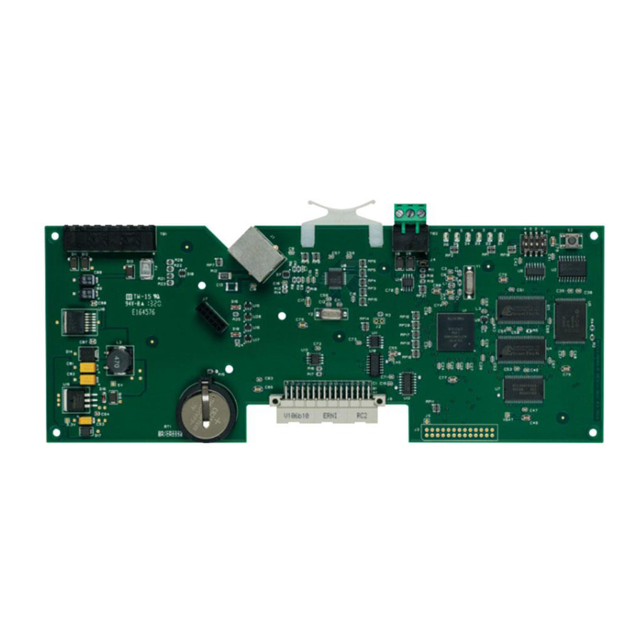
Overview of the LNL-3300-M5 The LNL-3300-M5 Board The LNL-3300-M5 is an Intelligent System Controller (ISC) that provides real-time processing for the I/O interfaces connected to it. The database for the subsystem configuration and card holders are stored in flash memory. The event log buffer is stored in battery-backed memory. - Page 36 LNL-3300-M5 Intelligent System Controller LNL-3300-M5 Board TMPR PFLT LNL-3300-M5 Board Callouts Callout Description J4: RS-485 terminator J6: to backplane in enclosure card cage J7: connection to optional Lantronix Micro125 Serial-to-Ethernet Module Battery: BR/CR2325, BR/CR2330 replace annually Standoff mounting holes for optional Lantronix Micro125 Serial-to-Ethernet Module.
-
Page 37: Default Login Security Enhancements
Overview With firmware version 1.194 or later, security enhancements were made regarding the default login account. These enhancements restrict the conditions in which the default login account is enabled, exposing the Lenel controllers to unauthorized access. Since the credentials (user name and password) for default login account are well-known and are the same on all of the controllers, it is important to reduce the possibility that the default login account is left enabled on controllers at customer sites. - Page 38 LNL-3300-M5 Intelligent System Controller • A user-defined account cannot be assigned “password” as its password (cannot be the same as the password for the default login account) • An error message appears if the credentials for the default login account are used when the credentials are not valid (see Error/Warning Messages on page 3 for details.)
- Page 39 M Series Installation Guide Login Failed: Login Time Window Expired The No User-defined Accounts screen appears when you successfully log into the controller, but no user- defined accounts are detected. No User-defined Accounts revision 7 —...
- Page 40 LNL-3300-M5 Intelligent System Controller When logging out, if either logout check (DIP switch settings or user-defined account) fails, the Configuration Manager screen appears. Configuration Manager If either, or both, condition exists, you must acknowledge the appropriate warning by checking the box next to I understand and wish to proceed before the Yes button under Do you wish to proceed? is enabled.
-
Page 41: Jumpers And Switches
For more information, refer to Communication Wiring on page 45. DIP Switches Use the four S1 DIP switches to configure the operating mode for the LNL-3300-M5. DIP switches are read on power-up (except where noted). Definition Normal operating mode. -
Page 42: Dual Nic Operation
LNL-3300-M5 Intelligent System Controller Dual NIC Operation Unless otherwise stated, use the following information to configure the LNL-3300-M5 for dual network card interface (NIC) operation. LNL-ETHLAN-MICR (Micro Serial Server) The ETHLAN-LITE/ETHLAN-MICR device plugs directly onto the LNL-3300-M5 panel and provides the ability to configure the controller for dual NIC operation. - Page 43 BOOTP and RARP are disabled using commands when configuring the device for use. DHCP is disabled when the device is shipped from Lenel. However, if an NVR reset is performed on the device, DHCP, BOOTP, and RARP will all be re-enabled and if there is a DHCP server on the network the unit will obtain an IP address automatically and you will not be able to use the ARP command for programming.
-
Page 44: Establish Network Communication
Remove all power from the LNL-3300-M5 for at least 15 seconds and then reapply power. Use the access control software to define the LNL-3300-M5 as a LAN panel at the IP address that was assigned. The panel will come online. -
Page 45: Wiring
M Series Installation Guide Wiring Communication Wiring The LNL-3300-M5 communicates to the host via: on-board Ethernet 10-BaseT/100Base-TX port and/or the optional Lantronix Ethernet 10-BaseT/100Base-TX Micro125 interface. TB2 is a 2-wire RS-485 interface that communicates to downstream controllers via the LNL-8000-MCOM (installed in downstream M5 enclosures). -
Page 46: Input Power, Enclosure Tamper, And Power Fault Input Wiring
LNL-3300-M5 Intelligent System Controller Input Power, Enclosure Tamper, and Power Fault Input Wiring The LNL-3300-M5 requires 12 VDC power, 3 A minimum. Depending on system configuration, a larger power supply may be required. There are three pairs of connections for power, all are in parallel. If needed, the other two pairs can supply power to other I/O boards. -
Page 47: Configuration
Web Configuration 10.1.1 Logging in for the First Time There is one pre-defined default user available on the LNL-3300-M5. To enable the default user, place DIP switch SW1 in the ON position after power-up. For more information, refer to DIP Switches on page 41. - Page 48 IP addresses. Configure an alternate host port if needed. Dual path communication is available on the LNL-3300-M5 only. If you opt not to use dual path communication, set this option to Disabled. Click [Accept]. To view information, click [Device Info].
- Page 49 M Series Installation Guide Access View allowed Edit allowed Network page Level 2: Yes Level 2: No Level 3: No Level 3: No Host Port page Level 2: Yes Level 2: No Level 3: No Level 3: No Device Info page Level 2: Yes Level 3: Yes Users page...
-
Page 50: Configuring The Lnl-3300-M5 In The Host Application
10.2 Configuring the LNL-3300-M5 in the Host Application Set up this controller as you would any other controller by using the LNL-3300-M5 Form in the Access Panels folder. The Access Panels folder is located in System Administration. Complete the form and its tabs as applicable for the installation site. -
Page 51: Other Functions
60 seconds. When complete, only LEDs 1 and 4 flash for 8 seconds. The LNL-3300-M5 reboots 8 seconds after LEDs 1 and 4 stop flashing (no LEDs are on during this time). Do not remove power when performing this procedure. -
Page 52: Status Leds
LNL-3300-M5 Intelligent System Controller Status LEDs • Power-up: All LEDs are OFF • Initialization: LED's 1 through 6 are sequenced during initialization. LED's 1, 3, and 5 turn ON for approximately 1.5 seconds after the hardware initialization is completed. The application code then initializes. The length of initialization time depends on the size of database (about 3 seconds without a card database). -
Page 53: Specifications
M Series Installation Guide Specifications The LNL-3300-M5 is intended for use in low voltage, Class 2 circuits only. The following specifications are subject to change without notice. • Primary Power: 12 VDC, ± 10%, 330 mA maximum (does not include other I/O modules connected to the backplane) •... - Page 54 LNL-3300-M5 Intelligent System Controller 54 — revision 7...
-
Page 55: Lnl-1100-20Di Input Control Module
LNL-1100-20DI INPUT CONTROL MODULE... -
Page 57: Overview Of The Lnl-1100-20Di
M Series Installation Guide Overview of the LNL-1100-20DI The LNL-1100-20DI is an Input Control Module that provides sensor monitoring via twenty (20) digital inputs that can be configured to support unsupervised or supervised alarm input circuits. The LNL-1100-20DI includes two (2) processors, each monitoring ten input circuits. The first processor (A) monitors inputs 1IN through 10IN. - Page 58 LNL-1100-20DI Input Control Module LNL-1100-20DI Input Control Module Callouts Callout Description Inputs monitored by Processor B Communication address defined by S1 incremented by one Inputs monitored by Processor A Communication address defined by S1 58 — revision 7...
-
Page 59: Setting The Device Address And Baud Rate
M Series Installation Guide Setting the Device Address and Baud Rate Use the on-board DIP switches to set the device address and communication baud rate on the LNL-1100-20DI. • Switches 1 to 5 are used to select the communication address for the first processor (A). The second processor (B) is assigned the next address value. - Page 60 LNL-1100-20DI Input Control Module LNL-1100-20DI DIP Switch Settings Selection Address 20 Address 21 Address 22 Address 23 Address 24 Address 25 Address 26 Address 27 Address 28 Address 29 Address 30 Address 31 - DO NOT USE 115,200 bps 9,600 bps 19,200 bps 38,400 bps Encrypted communication disabled...
-
Page 61: Alarm Input Wiring
M Series Installation Guide Alarm Input Wiring Typically, these inputs are used to monitor door position, request to exit, or alarm contacts. Input circuits can be configured as unsupervised or supervised. When unsupervised, reporting consists of only the open or closed states. - Page 62 LNL-1100-20DI Input Control Module Input Configuration Examples for TB1 through TB4 1K,1% 1K,1% 1K,1% 1K,1% Input Configuration Examples for TB1 through TB4 Callouts Callout Description Standard supervised circuit; normally closed contact Standard supervised circuit; normally open contact Unsupervised circuit; normally closed contact Unsupervised circuit;...
-
Page 63: Status Leds
M Series Installation Guide Status LEDs • Power-up: All LEDs are OFF Initialization: After power is applied, the board initializes Initialization complete: LEDs 1-4 briefly turn ON then OFF Run time: See the following descriptions for LEDs A1-A4 and B1-B4. •... -
Page 64: Specifications
The LNL-1100-20DI is intended for use in low voltage, Class 2 circuits only. The following specifications are subject to change without notice. • Primary Power: From the LNL-3300-M5; 12 VDC, ± 10 %, 165 mA maximum • Inputs: 20 unsupervised/supervised; Standard EOL: 1K/1K ohm, 1%, 1/4 watt •... -
Page 65: Lnl-1200-16Do Output Control Module
LNL-1200-16DO OUTPUT CONTROL MODULE... -
Page 67: Overview Of The Lnl-1200-16Do
M Series Installation Guide Overview of the LNL-1200-16DO The LNL-1200-16DO is an Output Control Module that provides digital output control via sixteen (16) open collector outputs rated at 40 mA maximum per output. An external DC power source is required for the digital outputs, 24 VDC maximum. - Page 68 LNL-1200-16DO Output Control Module LNL-1200-16DO Digital Output Control Module Callouts Callout Description Status LEDs External power source (24 VDC maximum) DIP switches 68 — revision 7...
-
Page 69: Setting The Device Address And Baud Rate
M Series Installation Guide Setting the Device Address and Baud Rate Use the on-board DIP switches to set the device address and communication baud rate on the LNL-1200-16DO. • Switches 1 to 5 select the device address. • Switches 6 and 7 select the communication baud rate. Note: Currently, OnGuard only supports a baud rate of 38,4000 bps. - Page 70 LNL-1200-16DO Output Control Module DIP Switch Settings for the LNL-1200-16DO Selection Address 20 Address 21 Address 22 Address 23 Address 24 Address 25 Address 26 Address 27 Address 28 Address 29 Address 30 Address 31 115,200 bps 119,600 bps 19,200 bps 38,400 bps Encrypted communication disabled Encrypted communication enabled...
-
Page 71: Digital Output Wiring
M Series Installation Guide Digital Output Wiring For typical use of the digital output, refer to the figure below. The open collector output drives an external relay, which in turn drives an output device. Note: Inductive load (relay or strike) switching causes EMI (electromagnetic interference) that can interfere with normal operation of other equipment. - Page 72 LNL-1200-16DO Output Control Module LNL-1200-DO Output Wiring Callouts Callout Description Coil resistance (125 ohm minimum) Suppression diode (see Suppression Diode Selection Notes below) +5 to +24 VDC; 40 mA maximum TB1 and TB5 terminal blocks on LNL-1200-16DO Digital output power source (+5 to +24 VDC) Suppression Diode Selection Notes: Diode current rating: >...
-
Page 73: Status Leds
M Series Installation Guide Status LEDs • Power-up: All LEDs are OFF Initialization: After power is applied, the board initializes Initialization complete: LEDs 1-4 briefly turn ON then OFF Run time: See the following descriptions for LEDs 1-4 • LED 1: Heartbeat and online status: Offline: 1 second cycle, 200 mS ON/800 mS OFF Online (non-encrypted communication): Flash cycle of 800 mS ON/200 mS OFF Online (encrypted communication): 4 flash cycles of 700 mS ON/300 mS OFF... -
Page 74: Specifications
The LNL-1200-16DO is intended for use in low voltage, Class 2 circuits only. The following specifications are subject to change without notice. • Primary Power (from LNL-3300-M5): 12 VDC, ± 10 %, 30 mA maximum • Power for Digital Outputs: 24 VDC maximum, 640 mA maximum •... -
Page 75: Lnl-1200-16Dor Output Control Module
LNL-1200-16DOR OUTPUT CONTROL MODULE... -
Page 77: Overview Of The Lnl-1200-16Dor
M Series Installation Guide Overview of the LNL-1200-16DOR The LNL-1200-16DO is an Output Control Module that provides digital output control via sixteen (16) open collector outputs rated at 40 mA maximum per output. An external DC power source is required for the digital outputs, 24 VDC maximum. - Page 78 LNL-1200-16DOR Output Control Module LNL-1200-16DOR Relay Output Control Module Callouts Callout Description DIP switches 78 — revision 7...
-
Page 79: Setting The Device Address And Baud Rate
M Series Installation Guide Setting the Device Address and Baud Rate Use the on-board DIP switches to set the device address and communication baud rate on the LNL-1200-16DOR. • Switches 1 to 5 select the device address. • Switches 6 and 7 select the communication baud rate. Note: Currently, OnGuard only supports a baud rate of 38,4000 bps. - Page 80 LNL-1200-16DOR Output Control Module DIP Switch Settings for the LNL-1200-16DOR Selection Address 20 Address 21 Address 22 Address 23 Address 24 Address 25 Address 26 Address 27 Address 28 Address 29 Address 30 Address 31 115,200 bps 119,600 bps 19,200 bps 38,400 bps Encrypted communication disabled Encrypted communication enabled...
-
Page 81: Relay Output Wiring
M Series Installation Guide Relay Output Wiring Eight (8) Form-C and eight Form-A contact relays control door lock mechanisms or alarm signaling devices. The relay contacts are rated at 2 A @ 30 VAC/DC, dry contact configuration. When controlling power to the door strike, the Normally Open and Common poles are used. When momentarily removing power to unlock the door, as with a magnetic lock, the Normally Closed and Common poles are used. - Page 82 LNL-1200-16DOR Output Control Module LNL-1200-16DOR Relay Definitions Relay Terminal Block Description TB3-4 Normally Closed (NC) TB3-5 Common (C) TB3-6 Normally Open (NO) TB3-7 Common (C) TB3-8 Normally Open (NO) TB3-9 Common (C) TB3-10 Normally Open (NO) TB4-1 Normally Closed (NC) TB4-2 Common (C) TB4-3...
- Page 83 M Series Installation Guide DC Door Strike Wiring Callouts Callout Description Fuse TB1 on LNL-1200-16DOR Suppression diode (see Suppression Diode Selection Notes below) Suppression Diode Selection Notes: Diode current rating: > 1x strike current. Diode break down voltage: 4x strike voltage. For 12 VDC or 24 VDC strike, use diode 1N4002 (100 V/1 A) typical.
-
Page 84: Status Leds
LNL-1200-16DOR Output Control Module Status LEDs • Power-up: All LEDs are OFF Initialization: After power is applied, the board initializes Initialization complete: LEDs 1-4 briefly turn ON then OFF Run time: See the following descriptions for LEDs 1-4 • LED 1: Heartbeat and online status: Offline: 1 second cycle, 200 mS ON/800 mS OFF Online (non-encrypted communication): Flash cycle of 800 mS ON/200 mS OFF Online (encrypted communication): 4 flash cycles of 700 mS ON/300 mS OFF... -
Page 85: Specifications
The LNL-1200-16DOR is intended for use in low voltage, Class 2 circuits only. The following specifications are subject to change without notice. • Primary Power (from LNL-3300-M5): 12 VDC, ± 10 %, 300 mA maximum • Power for Digital Outputs: 24 VDC maximum, 640 mA maximum •... - Page 86 LNL-1200-16DOR Output Control Module 86 — revision 7...
-
Page 87: Lnl-1320-2Rp Dual Door Control Module
LNL-1320-2RP DUAL DOOR CONTROL MODULE... -
Page 89: Overview Of The Lnl-1320-2Rp
M Series Installation Guide Overview of the LNL-1320-2RP The LNL-1320-2RP is a Dual Door Control Module that provides two (2) reader interface ports. The LNL-1320-2RP accepts data from readers with Clock/Data, Wiegand, F/2F, supervised F/2F signaling and door hardware. The LNL-1320-2RP provides LED status, strike control and reader power of 5 VDC or 12 VDC. - Page 90 LNL-1320-2RP Dual Door Control Module LNL-1320-2RP Dual Door Control Module Callouts Callout Description J6: to backplane in enclosure card cage Status LEDs DIP switches Reader Port 2 Reader Port 1 90 — revision 7...
-
Page 91: Configuration
M Series Installation Guide Configuration Configuring the LNL-1320-2RP consists of setting the device address and the power selection jumper. 30.1 Setting the Device Address and Baud Rate Use the on-board DIP switches to set the device address and communication baud rate on the LNL-1320-2RP. -
Page 92: Setting The Reader Power Selection Jumper (J5)
LNL-1320-2RP Dual Door Control Module DIP Switch Settings for the LNL-1320-2RP Selection Address 17 Address 18 Address 19 Address 20 Address 21 Address 22 Address 23 Address 24 Address 25 Address 26 Address 27 Address 28 Address 29 Address 30 Address 31 115,200 bps 119,600 bps... - Page 93 M Series Installation Guide J5 Reader Power Selection J5 Reader Power Selection Callouts Callout Description 5 VDC is available on both reader interface ports 12 VDC is available on both reader interface ports revision 7 —...
-
Page 94: Reader Wiring
LNL-1320-2RP Dual Door Control Module Reader Wiring The reader ports on the LNL-1320-2RP support the following reader types: • Clock/Data • Wiegand • F/2F • Supervised F/2F The following are basic reader cable requirements. For more information, refer to Specifications page 107. - Page 95 M Series Installation Guide Wiegand Reader Callouts Callout Description Terminal 4: Door DO (Reader LED) connection Terminal 6: Data 0 connection Terminal 7: Data 1 connection Magnetic Reader DISP REX+ Not Used CLK DO Magnetic Reader Callouts Callout Description Magnetic reader TB1 or TB3 on LNL-1320-2RP Terminal 1: +5 VDC/+12 VDC connection Terminal 2: Ground connection...
- Page 96 LNL-1320-2RP Dual Door Control Module F/2F Reader DISP REX+ Not Used CLK DO F/2F Reader Callouts Callout Description F/2F reader TB1 or TB3 on LNL-1320-2RP Terminal 1: +5 VDC/+12 VDC connection Terminal 2: Ground connection Terminal 4: Door DO (Reader LED) connection Terminal 7: Data 1 connection 96 —...
-
Page 97: Door Position Monitor And Rex Input Wiring
M Series Installation Guide Supervised F/2F Reader DISP REX+ Not Used CLK DO Supervised F/2F Reader Callouts Callout Description Supervised F/2F reader TB1 or TB3 on LNL-1320-2RP Terminal 1: +5 VDC/+12 VDC connection Terminal 2: Ground connection Terminal 3: Display DO connection Terminal 4: Door DO (Reader LED) connection Terminal 7: Data 1 connection Wire jumper to Terminal 3 (Display DO) - Page 98 LNL-1320-2RP Dual Door Control Module 31.2.1 Unsupervised Inputs wired to the LNL-1320-2RP Unsupervised inputs for the door position monitor and REX switches are wired to TB1 for the first reader, and TB3 for the second reader. End-of-Line (EOL) resistors are not required. Unsupervised Input Wiring on LNL-1320-2RP DISP REX+...
- Page 99 M Series Installation Guide Unsupervised Input Wiring on F/2F Reader Unsupervised Input Wiring on F/2F Reader Callouts Callout Description F/2F reader To LNL-1320-2RP +5 VDC/+12 VDC connection Ground connection Door DO (reader LED) connection Data 1 connection Normally Closed contact for door monitor switch Normally Open contact for Request-to-Exit (REX) switch 31.2.3 Supervised Inputs wired to the F/2F Reader...
-
Page 100: Door Strike Wiring
LNL-1320-2RP Dual Door Control Module Supervised Input Wiring on F/2F Reader 1K,1% 1K,1% 1K,1% 1K,1% Supervised Input Wiring on F/2F Reader Callouts Callout Description Supervised F/2F reader To LNL-1320-2RP +5 VDC/+12 VDC connection Ground connection Door DO (reader LED) connection Data 1 connection Normally Closed contact for door monitor switch Normally Open contact for REX switch... - Page 101 M Series Installation Guide Note: Excessive load switching causes contact wear and premature failure. Inductive load (strike) switching causes EMI (electromagnetic interference) that can interfere with normal operation of other equipment. To minimize premature contact failure and to increase system reliability, use a contact protection circuit.
- Page 102 LNL-1320-2RP Dual Door Control Module AC Door Strike Wiring using Internal Relay AC Door Strike Wiring using Internal Relay Callouts Callout Description AC strike To AC power source Fuse TB2 or TB4 on LNL-1320-2RP Suppression MOV DC Door Strike Wiring Suppression diode selection: Diode current rating: >1x strike current Diode breakdown voltage: 4x strike voltage...
- Page 103 M Series Installation Guide DC Door Strike Wiring using Internal Relay DC Door Strike Wiring using Internal Relay Callouts Callout Description DC strike To DC power source Fuse TB2 or TB4 on LNL-1320-2RP Suppression diode 31.3.2 External Relay Door Strike Wiring Instead of using the on-board relay to control the door strike, an external relay may be used.
- Page 104 LNL-1320-2RP Dual Door Control Module (12 inches [30cm] recommended). The circuit's effectiveness decreases if it is located further away. AC Door Strike Wiring AC Door Strike Wiring using External Relay DISP REX+ Not Used CLK DO AC Door Strike Wiring using External Relay Callouts Callout Description AC strike...
- Page 105 M Series Installation Guide DC Door Strike Wiring DC Door Strike Wiring using External Relay DISP REX+ Not Used CLK DO DC Door Strike Wiring using External Relay Callouts Callout Description DC strike To DC power source Fuse External relay TB1 or TB3 on LNL-1320-2RP Terminal 1: +5 VDC/+12 VDC connection for LNL-1320-S2RP Terminal 4: Reader LED connection...
-
Page 106: Status Leds
LNL-1320-2RP Dual Door Control Module Status LEDs • Power-up: All LEDs are OFF Initialization: After power is applied, the board initializes Initialization complete: LEDs 1-4 briefly turn ON then OFF Run time: See the following descriptions for LEDs 1-4 • LED 1: Heartbeat and online status: Offline: 1 second cycle, 200 mS ON/800 mS OFF Online (non-encrypted communication): Flash cycle of 800 mS ON/200 mS OFF... -
Page 107: Specifications
M Series Installation Guide Specifications • Primary Power (from LNL-3300-M5): 12 VDC, ± 10 %, 155 mA maximum (plus reader current) • Relay Outputs: 6 outputs, Form-C, 2 A @ 30 VAC/DC, resistive • Inputs: 4 unsupervised, two per reader port •... - Page 108 LNL-1320-2RP Dual Door Control Module 108 — revision 7...
-
Page 109: Lnl-1320-S2Rp Dual Door Control Module
LNL-1320-S2RP DUAL DOOR CONTROL MODULE... -
Page 111: Overview Of The Lnl-1320-S2Rp
M Series Installation Guide Overview of the LNL-1320-S2RP The LNL-1320-S2RP is a Dual Door Control Module that provides four (4) supervised inputs (two per reader interface port). The LNL-1320-S2RP accepts data from readers with Clock/Data, Wiegand, F/2F, supervised F/2F signaling and door hardware. - Page 112 LNL-1320-S2RP Dual Door Control Module LNL-1320-S2RP Dual Door Control Module Callouts Callout Desscription J6: to backplane in enclosure card cage Status LEDs DIP switches Reader Port 2 Reader Port 1 112 — revision 7...
-
Page 113: Configuration
M Series Installation Guide Configuration Configuring the LNL-1320-S2RP consists of setting the device address and the power selection jumper. 35.1 Setting the Device Address and Baud Rate Use the on-board DIP switches to set the device address and communication baud rate on the LNL-1320-S2RP. -
Page 114: Setting The Reader Power Selection Jumper (J5)
LNL-1320-S2RP Dual Door Control Module DIP Switch Settings for the LNL-1320-S2RP Selection Address 17 Address 18 Address 19 Address 20 Address 21 Address 22 Address 23 Address 24 Address 25 Address 26 Address 27 Address 28 Address 29 Address 30 Address 31 115,200 bps 119,600 bps... - Page 115 M Series Installation Guide J5 Reader Power Selection J5 Reader Power Selection Callouts Callout Description 5 VDC is available on both reader interface ports 12 VDC is available on both reader interface ports revision 7 —...
-
Page 116: Reader Wiring
LNL-1320-S2RP Dual Door Control Module Reader Wiring The reader ports on the LNL-1320-S2RP support the following reader types: • Clock/Data • Wiegand • F/2F • Supervised F/2F The following are basic reader cable requirements. For more information, refer to Specifications page 130. - Page 117 M Series Installation Guide Wiegand Reader Callouts Callout Description Terminal 4: Door DO (Reader LED) connection Terminal 6: Data 0 connection Terminal 7: Data 1 connection Magnetic Reader DISP REX+ REX- Magnetic Reader Callouts Callout Description Magnetic reader TB1 or TB3 on LNL-1320-S2RP Terminal 1: +5 VDC/+12 VDC connection Terminal 2: Ground connection Terminal 4: Door DO (Reader LED) connection...
- Page 118 LNL-1320-S2RP Dual Door Control Module F/2F Reader DISP REX+ REX- F/2F Reader Callouts Callout Description F/2F reader TB1 or TB3 on LNL-1320-S2RP Terminal 1: +5 VDC/+12 VDC connection Terminal 2: Ground connection Terminal 4: Door DO (Reader LED) connection Terminal 7: Data 1 connection 118 —...
-
Page 119: Door Position Monitor And Rex Input Wiring
M Series Installation Guide Supervised F/2F Reader DISP REX+ REX- Supervised F/2F Reader Callouts Callout Description Supervised F/2F reader TB1 or TB3 on LNL-1320-S2RP Terminal 1: +5 VDC/+12 VDC connection Terminal 2: Ground connection Terminal 3: Display DO connection Terminal 4: Door DO (Reader LED) connection Terminal 7: Data 1 connection Wire jumper to Terminal 3 (Display DO) 36.2... - Page 120 LNL-1320-S2RP Dual Door Control Module 36.2.1 Supervised Inputs wired to the LNL-1320-S2RP Supervised inputs for the door position monitor and REX switches are wired to TB1 for the first reader, and TB3 for the second reader. Two sets of End-Of-Line (EOL) resistor pairs are supported by the S2RP board. Either two 1K ohm resistors, or a 6.8K and 18K ohm resistor set must be installed as shown in the following figures.
- Page 121 M Series Installation Guide Supervised Input Wiring with 1K/1K EOL Callouts Callout Description Normally Closed contact for door monitor switch Supervised Input Wiring with 6.8K/18K EOL DISP 6.8K,5% REX+ 18K,5% 6.8K,5% 18K,5% REX- Supervised Input Wiring with 6.8K/18K EOL Callouts Callout Description TB1 or TB3 on LNL-1320-S2RP...
- Page 122 LNL-1320-S2RP Dual Door Control Module Unsupervised Input Wiring on F/2F Reader Unsupervised Input Wiring on F/2F Reader Callouts Callout Description F/2F reader To LNL-1320-S2RP +12 VDC connection Ground connection Door DO (reader LED) connection Data 1 connection Normally Closed contact for door monitor switch Normally Open contact for REX switch 36.2.3 Supervised Inputs wired to the F/2F Reader...
-
Page 123: Door Strike Wiring
M Series Installation Guide Supervised Input Wiring on F/2F Reader 1K,1% 1K,1% 1K,1% 1K,1% Supervised Input Wiring on F/2F Reader Callouts Callout Description Supervised F/2F reader To LNL-1320-S2RP +5 VDC/+12 VDC connection Ground connection Door DO (reader LED) connection Data 1 connection Normally Closed contact for door monitor switch Normally Open contact for REX switch 36.3... - Page 124 LNL-1320-S2RP Dual Door Control Module Note: Excessive load switching causes contact wear and premature failure. Inductive load (strike) switching causes EMI (electromagnetic interference) that can interfere with normal operation of other equipment. To minimize premature contact failure and to increase system reliability, use a contact protection circuit.
- Page 125 M Series Installation Guide AC Door Strike Wiring using Internal Relay AC Door Strike Wiring using Internal Relay Callouts Callout Description AC strike To AC power source Fuse TB2 or TB4 on LNL-1320-S2RP Suppression MOV DC Door Strike Wiring Suppression diode selection: Diode current rating: >1x strike current Diode breakdown voltage: 4x strike voltage For 12 VDC or 24 VDC strike, use diode 1N4002 (100 V/1 A) typical...
- Page 126 LNL-1320-S2RP Dual Door Control Module DC Door Strike Wiring using Internal Relay DC Door Strike Wiring using Internal Relay Callouts Callout Description DC strike To DC power source Fuse TB2 or TB4 on LNL-1320-S2RP Suppression diode 36.3.2 External Relay Door Strike Wiring Instead of using the on-board relay to control the door strike, an external relay may be used.
- Page 127 M Series Installation Guide (12 inches [30cm] recommended). The circuit's effectiveness decreases if it is located further away. AC Door Strike Wiring AC Door Strike Wiring using External Relay DISP REX+ REX- AC Door Strike Wiring using External Relay Callouts Callout Description AC strike...
- Page 128 LNL-1320-S2RP Dual Door Control Module DC Door Strike Wiring DC Door Strike Wiring using External Relay DISP REX+ REX- DC Door Strike Wiring using External Relay Callouts Callout Description DC strike To DC power source Fuse External relay TB1 or TB3 on LNL-1320-S2RP Terminal 1: +5 VDC/+12 VDC connection for LNL-1320-S2RP Terminal 4: Reader LED connection Suppression diode...
-
Page 129: Status Leds
M Series Installation Guide Status LEDs • Power-up: All LEDs are OFF Initialization: After power is applied, the board initializes Initialization complete: LEDs 1-4 briefly turn ON then OFF Run time: See the following descriptions for LEDs 1-4 • LED 1: Heartbeat and online status: Offline: 1 second cycle, 200 mS ON/800 mS OFF Online (non-encrypted communication): Flash cycle of 800 mS ON/200 mS OFF Online (encrypted communication): 4 flash cycles of 700 mS ON/300 mS OFF... -
Page 130: Specifications
LNL-1320-S2RP Dual Door Control Module Specifications • Primary Power (from LNL-3300-M5): 12 VDC, ± 10 %, 155 mA maximum (plus reader current) • Relay Outputs: 6 outputs, Form-C, 2 A @ 30 VAC/DC, resistive • Inputs: 4 unsupervised, two per reader port •... -
Page 131: Lnl-1340-M2K Four Reader Interface Module
LNL-1340-M2K FOUR READER INTERFACE MODULE... -
Page 133: Overview Of The Lnl-1340-M2K
The LNL-3300-M5 Intelligent System Controller board can be mounted directly on the LNL-1340-M2K board. The LNL-1340-M2K can only be installed in an M2000 enclosure. If the LNL-3300-M5 board is mounted on the LNL-1340-M2K board, it is powered by the LNL-1340-M2K board's internal power supply. - Page 134 LNL-3300- LNL-1340- TB12 TB11 TB10 TMPR PFLT M2000 Enclosure with LNL-3300-M5 and LNL-1340-M2K Callouts Callout Description No connections on LNL-3300-M5 TB1 Connect to Earth Ground Connect to Chassis Ground LNL-1340-M2K DIP Switches Replace Card Puller with Mounting Screws, two (2) each...
- Page 135 M Series Installation Guide M2000 Enclosure with LNL-3300-M5 and LNL-1340-M2K Callouts Callout Description LNL-3300-M5 Reset Switch Mounting Holes 4x TB1, PIN1: Inputs 1-5 TB2, PIN 1: Inputs 6-10 TB3, PIN 1: Reader 1 TB4, PIN 1: Reader 2 TB5, PIN 1: Reader 3...
- Page 136 LNL-1340-M2K Four Reader interface Module LNL-3300-M5 Board TMPR PFLT LNL-3300-M5 Board Callouts Callout Description J4: RS-485 terminator J6: to backplane in enclosure card cage J7: connection to optional Lantronix Micro125 Serial-to-Ethernet Module Battery: BR/CR2325, BR/CR2330 replace annually Standoff mounting holes for optional Lantronix Micro125 Serial-to-Ethernet Module.
- Page 137 Description Card puller Warning The card puller must be removed from the LNL-3300-M5 board before mounting it to the LNL-1340-M2K board. Install two (2) mounting screws [7b] in the holes made vacant from the card puller. Mounting Screws, 2 places...
-
Page 138: Configuration
LNL-1340-M2K Four Reader interface Module Configuration Configuring the LNL-1340-M2K consists of setting the device address and the power selection jumper. 40.1 Setting the Device Address and Baud Rate Use the on-board DIP switches to set the device address and communication baud rate on the LNL-1340- M2K. -
Page 139: Input Power, Enclosure Tamper, And 12 Volt Battery Wiring
Input Power, Enclosure Tamper, and 12 Volt Battery Wiring Input power for the LNL-1340-M2K/LNL-3300-M5 assembly is provided by a wall mount 18 VAC transformer @ 2.78 A (334 VA) connected to TB8 pins 1 and 2. The internal supply supplies power to the LNL-1340-M2K/LNL-3300-M5 assembly, and charging current for a 12 V, 7 Ah rechargeable battery. -
Page 140: Ethernet Grounding
40.3 Ethernet Grounding The grounding lug on the LNL-3300-M5, identified as “CGND” (located next to the Ethernet jack), must be connected to the chassis/earth ground stud on the M2000 enclosure. It is recommended to use braided wire and make the connection is as short as possible. -
Page 141: Wiring
1. This communication port also appears on TB7 of the LNL-1340-M2K. An additional 31 downstream I/O devices can be supported on this communication port. If the LNL-3300-M5 is mounted on the LNL-1340-M2K, TB2 of the LNL-3300-M5 is the 2-wire RS-485 downstream communication port 2 that can communicate to an additional 32 downstream I/O devices. - Page 142 LNL-1340-M2K Four Reader interface Module LNL-1340-M2K to F/2F or Supervised F/2F Reader Wiring (LED) LNL-1340-M2K to F/2F or Supervised F/2F Reader Wiring Callouts Callout Description F/2F reader TBx on LNL-1340-M2K TBx-1: 12 VDC connection TBx-2: Ground connection TBx-3: Door DI connection TBx-4: Door DOx (Reader LED) connection 142 —...
- Page 143 M Series Installation Guide LNL-1340-M2K Reader Port Terminal Block Definitions TB3: Reader Port 1 TB4: Reader Port 2 TB5: Reader Port 3 TB6: Reader Port 4 TB3-1 12 VDC TB4-1 12 VDC TB5-1 12 VDC TB6-1 12 VDC TB3-2 TB4-2 TB5-2 TB6-2 TB3-3...
- Page 144 LNL-1340-M2K Four Reader interface Module Supervised F/2F Reader 4-State Input Wiring 1K,1% 1K,1% 1K,1% 1K,1% Supervised F/2F Reader 4-State Input Wiring Callouts Callout Description F/2F reader To LNL-1340-M2K +5 VDC/+12 VDC connection Ground connection Data 1 connection Door DO (reader LED) connection Normally Closed contact for door monitor switch Normally Open contact for REX switch Unsupervised Inputs Wired to the F/2F Reader...
- Page 145 M Series Installation Guide Supervised F/2F Reader 2-State Input Wiring Supervised F/2F Reader 2-State Input Wiring Callouts Callout Description Supervised F/2F reader To LNL-1340-M2K +12 VDC connection Ground connection Door DO (reader LED) connection Data 1 connection Normally Closed contact for door monitor switch Normally Open contact for REX switch 41.2.2 Input Wiring...
- Page 146 LNL-1340-M2K Four Reader interface Module facilitate proper reporting. The standard supervised circuit requires 1K Ohm, 1% resistors and should be located as close to the sensor as possible. Custom End-of-Line (EOL) resistances may be configured via the host software. * Grounded and foreign voltage states are not UL 294 required and therefore not verified by UL. The input circuit wiring configurations shown are supported, but may not be typical: LNL-1340-M2K Input Wiring - Supervised and Non-supervised 1K,1%...
- Page 147 M Series Installation Guide LNL-1340-M2K Input Terminal Block Definitions TB1: Inputs 1 - 5 TB2: Inputs 6 - 10 TB1-1 DI 1 TB2-1 DI 6 TB1-2 DI 1 return TB2-2 DI 6 return TB1-3 DI 2 TB2-3 DI 7 TB1-4 DI 2 return TB2-4 DI 7 return...
- Page 148 LNL-1340-M2K Four Reader interface Module DC Door Strike Wiring using External Relay DC Door Strike Wiring using External Relay Callouts Callout Description DC strike To DC power source Fuse External relay TB1 on LNL-1340-M2K Terminal 1: +12 VDC connection for LNL-1340-M2K Terminal 4: Reader LED connection Suppression diode (2) To reader’s green LED input...
- Page 149 M Series Installation Guide AC Door Strike Wiring using External Relay AC Door Strike Wiring using External Relay Callouts Callout Description AC strike AC transformer Fuse External relay TB1 on LNL-1340-M2K Terminal 1: +12 VDC connection for LNL-1340-M2K Terminal 4: Reader LED connection Suppression diode To reader’s green LED input Blocking diode (1N5817 or equivalent)
- Page 150 LNL-1340-M2K Four Reader interface Module load as possible (12 inches [30cm] maximum recommended). The circuit's effectiveness decreases if it is located farther away. Use sufficiently large gauge wire for the load current to avoid voltage loss. LNL-1340-M2K Relay Terminal Block Definitions TB9: Relays TB10: Relays TB11: Relays...
- Page 151 M Series Installation Guide DC Door Strike Wiring - Internal Relay Callouts Callout Description DC strike To DC power source Fuse TB9, TB10, TB11, and TB12 on LNL-1340-M2K Suppression diode AC Door Strike Wiring Suppression MOV selection: Clamp voltage: >1.5x VAC RMS For 24 VAC strike, Panasonic ERZ-C07DK470 typical AC Door Strike Wiring - Internal Relay AC Door Strike Wiring - Internal Relay Callouts...
-
Page 152: Status Leds
LNL-1340-M2K Four Reader interface Module Status LEDs • Power-up: All LEDs are OFF Initialization: After power is applied, the board initializes Initialization complete: LEDs 1-4 briefly turn ON then OFF Run time: See the following descriptions for LEDs 1-6 • LED 1: Heartbeat and online status: Offline: 1 second cycle, 200 mS ON/800 mS OFF Online (non-encrypted communication): Flash cycle of 800 mS ON/200 mS OFF... -
Page 153: Ul 294 Installations
M Series Installation Guide UL 294 Installations For UL294 installations, the LNL-1340-M2K has been evaluated to the following: Model Destructive Line Security Endurance Standby Attack (Encryption) Power LNL-1340-M2K revision 7 —... -
Page 154: Specifications
Width: 8.375 in (212.7 mm) Length: 11.375 in (289.1 mm) Height: 1.04 in (26.5 mm) without LNL-3300-M5 1.27 in (32.26 mm) with LNL-3300-M5 Weight (without connectors): 12.0 oz. (340.2 g) nominal without LNL-3300-M5 17.3 oz. (491.0 g) nominal with LNL-3300-M5 154 — revision 7... -
Page 155: Lnl-1380-8Rp Reader Interface Module
LNL-1380-8RP READER INTERFACE MODULE... -
Page 157: Overview Of The Lnl-1380-8Rp
M Series Installation Guide Overview of the LNL-1380-8RP The LNL-1380-8RP is a Reader Interface Module that provides eight (8) reader interface ports. The LNL-1380-8RP accepts data only from readers with supervised F/2F signaling. The door position and Request-to-Exit (REX) inputs are reported through the F/2F reader data line. The LNL-1380-8RP also provides LED status, external strike relay control, and 12 VDC reader power. - Page 158 LNL-1380-8RP Reader Interface Module LNL-1380-8RP Board Callouts Callout Description Reader 8 Reader 7 Reader 6 Reader 5 Reader 4 Reader 3 Reader 2 Reader 1 158 — revision 7...
-
Page 159: Configuration
M Series Installation Guide Configuration Configuring the LNL-1380-8RP consists of setting the device address and the power selection jumper. 46.1 Setting the Device Address and Baud Rate Use the on-board DIP switches to set the device address and communication baud rate on the LNL-1380-8RP. -
Page 160: Setting The Reader Interface Power Selection Jumper (J3)
LNL-1380-8RP Reader Interface Module DIP Switch Settings for the LNL-1380-8RP Selection Address 17 Address 18 Address 19 Address 20 Address 21 Address 22 Address 23 Address 24 Address 25 Address 26 Address 27 Address 28 Address 29 Address 30 Address 31 115,200 bps 119,600 bps 19,200 bps... -
Page 161: Wiring
46.3.1 Additional Power Wiring for Second LNL-1380-8RP If installing two LNL-1380-8RPs, additional power must be supplied to the second LNL-1380-8RP from the LNL-3300-M5. Note: The 12V output for Reader Port 7 on the second LNL-1380-8RP is not current-limited. revision 7 —... - Page 162 Callout Description LNL-3300-M5 Intelligent System Controller LNL-1380-8RP Reader Interface Module 12 VDC connection: TB1-1 (VIN) on LNL-3300-M5 to TB4-1 (12V) on LNL-1380-8RP Ground connection 46.3.2 Reader Interface Module to Reader Wiring The reader ports on the LNL-1380-8RP Reader Interface Module only support 12V supervised F/2F type readers.
- Page 163 M Series Installation Guide LNL-1380-8RP to Supervised F/2F Reader Wiring LNL-1380-8RP to Supervised F/2F Reader Wiring Callouts Callout Description Supervised F/2F reader TB1 on LNL-1380-8RP TB1-1: 12 VDC connections TB1-2: Ground connection TB1-3: Reader Data 1 connection TB1-4: Door DO (Reader LED) connection 46.3.3 Door Position Monitor and REX Input Wiring Typically, the door position monitor switch uses the Normally Closed (NC) contact and the REX uses the...
- Page 164 LNL-1380-8RP Reader Interface Module Unsupervised Input Wiring on the F/2F Reader Unsupervised Input Wiring on the F/2F Reader Callouts Callout Description F/2F reader To LNL-1380-8RP +5 VDC/+12 VDC connection Ground connection Door DO (reader LED) connection Data 1 connection Normally Closed contact for door monitor switch Normally Open contact for REX switch Supervised Inputs wired to the F/2F Reader For 4-State Supervision, wire supervised inputs for the door position monitor and REX switches directly to...
- Page 165 M Series Installation Guide Supervised Input Wiring on the F/2F Reader Supervised Input Wiring on the F/2F Reader Callouts Callout Description Supervised F/2F reader To LNL-1380-8RP +12 VDC connection Ground connection Door DO (reader LED) connection Data 1 connection Normally Closed contact for door monitor switch Normally Open contact for REX switch 46.3.4 Door Strike Wiring using an External Relay...
- Page 166 LNL-1380-8RP Reader Interface Module The 12 volt relay coil resistance must be 300 or greater ohms. Note: Excessive load switching causes contact wear and premature failure. Inductive load (strike) switching causes EMI (electromagnetic interference) that can interfere with normal operation of other equipment.
- Page 167 M Series Installation Guide DC Door Strike Wiring DC Door Strike Wiring using External Relay DATA DATA DC Door Strike Wiring using External Relay Callouts Callout Description DC strike To DC power source Fuse External relay TB1, TB2, TB3, or TB4 on LNL-1380-8RP Terminal 1: +12 VDC connection for LNL-1380-8RP Terminal 4: Reader LED connection Suppression diode...
-
Page 168: Status Leds
LNL-1380-8RP Reader Interface Module Status LEDs • Power-up: All LEDs are OFF Initialization: After power is applied, the board initializes Initialization complete: LEDs 1-4 briefly turn ON then OFF Run time: See the following descriptions for LEDs 1-4 • LED 1: Heartbeat and online status: Offline: 1 second cycle, 200 mS ON/800 mS OFF Online (non-encrypted communication): Flash cycle of 800 mS ON/200 mS OFF Online (encrypted communication): 4 flash cycles of 700 mS ON/300 mS OFF... -
Page 169: Specifications
M Series Installation Guide Specifications • Primary Power (from LNL-3300-M5): 12 VDC, ± 10 %, 36 mA maximum (plus reader current) • Inputs: Two EOL values supported: 1K/1K ohm, 1%, 1/4 watt 6.8K/18K ohm, 5%, 1/4 watt • Reader Interface:... - Page 170 LNL-1380-8RP Reader Interface Module 170 — revision 7...
-
Page 171: Lnl-8000-Mcom Rs-485 Interface Module
LNL-8000-MCOM RS-485 INTERFACE MODULE... -
Page 173: Overview Of The Lnl-8000-Mcom
LNL-3300-M5 Intelligent System Controller (ISC), to downstream controller enclosures. The LNL-8000-MCOM accepts 12 VDC power and two-wire RS-485 communication. A local 12 VDC power supply powers the I/O modules in the controller enclosure. The LNL-3300-M5 (located in the first controller enclosure) communicates with the downstream controller enclosure using multi-drop two-wire RS-485. -
Page 174: Wiring
Terminal Block 2 (TB2) is a two-wire RS-485 interface that communicates to upstream and downstream controller enclosures. TB2 on the LNL-3300-M5 (located in the first M5 enclosure) is wired to TB2 on the LNL-8000-MCOM in each downstream enclosure. This interface allows multi-drop communication on a single bus up to 4,000 ft. (1,200 m). -
Page 175: Input Power Wiring
M Series Installation Guide 50.2 Input Power Wiring The LNL-8000-MCOM requires 12 VDC power, 3 A minimum. This power is passed through to the back plane to power the I/O modules in the M5 enclosure. There are three pairs of connections for power, all in parallel, on Terminal Block 1 (TB1). If needed, the other two pairs can supply power to the other I/O boards. -
Page 176: Enclosure Tamper And Power Fault Wiring
LNL-8000-MCOM RS-485 Interface Module 50.3 Enclosure Tamper and Power Fault Wiring The LNL-3300-M5 has two dedicated inputs for enclosure tamper (TMPR) and UPS fault monitoring (PFLT). The LNL-8000-MCOM installed in downstream controller enclosures does not have these dedicated inputs. There are three options available to wire tamper and power fault switches in downstream controller enclosures: •... -
Page 177: Specifications
M Series Installation Guide Specifications • Primary Power: Not applicable. Power is passed through and supplies power to the controller enclosure back plane. • Communication: Two-wire RS-485 at 9600, 19200, 38400, or 115200 bps, asynchronous, passed through to the back plane. •... - Page 178 LNL-8000-MCOM RS-485 Interface Module 178 — revision 7...
-
Page 179: Index
LNL-1320-S2RP........113 LNL-1100-20DI ........59 LNL-1340-M2K ........138 LNL-1200-16DO........69 LNL-1380-8RP .......... 159 LNL-1200-16DOR ....... 79 LNL-3300-M5 ..........41 LNL-1320-2RP........91 Door LNL-1320-S2RP......... 113 AC strike wiring LNL-1340-M2K ......... 138 external relay ... 104, 127, 149, 166 LNL-1380-8RP........159 internal relay... - Page 180 Index LNL-1340-M2K ......... 139 DIP switches ..........59 LNL-3300-M5 ........46 setting the baud rate ........59 LNL-8000-MCOM ......176 setting the device address ......59 Ethernet grounding specifications ..........64 LNL-1340-M2K ........140 status LEDs..........63 LNL-1200-16DO DIP switches ..........69 setting the baud rate ........
- Page 181 M Series Installation Guide setting the device address ......138 specifications ..........154 Memory status LEDs..........152 LNL-3300-M5 ..........51 LNL-1340-MK2 Mounting four reader interface module...... 133 guidelines............. 14 wiring instructions........... 15 12 volt battery........139 enclosure tamper......... 139 input power......... 139...
- Page 182 Index supervised F/2F wiring ....... 97, 119 LNL-1380-8RP .......... 168 troubleshooting ..........24 LNL-3300-M5 ..........52 Wiegand Supervised wiring........... 94, 116 F/2F reader wiring wiring..........94, 116 to LNL-1320-S2RP ..... 97, 119 Relay inputs external, AC door strike LNL-1320-S2RP ........ 111 wiring.......
- Page 183 LNL-1200-16DOR ....... 82 door position monitor ......97, 119 dual door control module to reader..94, 116 enclosure tamper LNL-1340-MK2 ......... 139 LNL-3300-M5 ........46 LNL-8000-MCOM ......176 external relay door strike ....103, 126 input power LNL-8000-MCOM ......175 internal relay door strike....
- Page 184 UTC Fire & Security Americas Corporation, Inc. 1212 Pittsford-Victor Road Pittsford, New York 14534 USA Tel 866.788.5095 Fax 585.248.9185 www.lenel.com docfeedback@lenel.com...