Motorola E815 Service Manual
Level 2
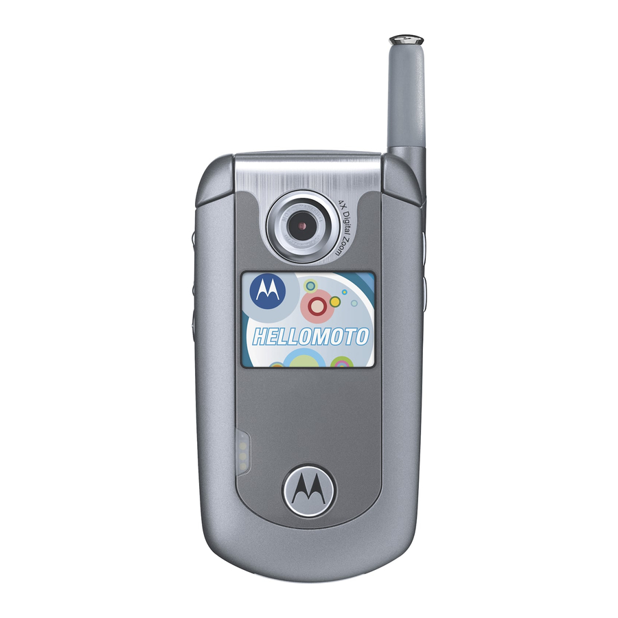
digital wireless telephone
Hide thumbs
Also See for E815:
- User manual (264 pages) ,
- Manual (136 pages) ,
- Configuring manual (3 pages)

Related Manuals for Motorola E815


Summary of Contents for Motorola E815
- Page 1 Level 2 Service Manual 6809492A18-B E815, E816 Digital Wireless Telephone CDMA 800/1900 MHz...
-
Page 3: Table Of Contents
Level 2 Service Manual Contents E815, E816 6809492A18-B Introduction ................4 Product Identification . -
Page 4: Introduction
Available on a contract basis, Motorola Inc. offers comprehensive maintenance and installation programs that enable customers to meet requirements for reliable, continuous communications. To learn more about the wide range of Motorola service programs, contact your local Motorola products representative or the nearest Customer Service Manager. Product Identification Motorola products are identified by the model number on the housing. -
Page 5: Computer Program Copyrights
The Motorola products described in this manual may include Motorola computer programs stored in semiconductor memories or other media that are copyrighted with all rights reserved worldwide to Motorola. Laws in the United States and other countries preserve for Motorola, Inc. certain exclusive rights to the copyrighted... -
Page 6: Warranty Service Policy
Customer’s original units will be repaired but not refurbished as standard. Appointed Motorola Service Hubs will perform warranty and non-warranty field service for level 2 (assemblies) and level 3 (limited PCB component). The Motorola High Technology Centers will perform level 4 (full component) repairs. -
Page 7: Parts Replacement
When ordering replacement parts or equipment, include the Motorola part number and description used in the service manual or supplement. When the Motorola part number of a component is not known, use the product model number or other related major assembly along with a description of the related major assembly and of the component in question. -
Page 8: Specifications
Specifications E815, E816 CDMA Specifications General Function Specification Frequency Range 1900 MHz PCS 1931.250 -1988.750 MHz Rx 1851.250 -1908.750 MHz Tx Frequency Range 800 MHz CDMA 869.04 - 893.97 Rx 824.04 - 848.97 Tx Channel Spacing 50 kHz PCS 30 kHz CDMA... -
Page 9: Product Overview
VibraCall vibrating alert and 32 Downloadable/Customizable iMelody ring tones. The phone also contains a TransFlash removable memory expansion slot. The E815 is a dual band phone that allows roaming within the CDMA 800 and 1900 MHz bands. The E815 CDMA phone consists of a main housing assembly and a flip assembly. - Page 10 Personal Information Management The E815 telephone contains a built in calendar with alarm reminders message center and a 1000 number capacity phonebook. Phonebook and calendar can be synchronized with a PC using optional Mobile Phone tools software.
-
Page 11: General Operation
General Operation Controls, Indicators, and Input/Output (I/O) Connectors The E815 telephones’ controls are on the front and side of the device, and on the keyboard as shown in Figure 1. Other hardware features are shown in Figure 2. Left Soft Key... - Page 12 A 5-way navigation key allows you to move easily through menus. Color Display The E815 phone features a 128 x160 pixel, 262K color display. The display provides constant graphical representations of battery capacity and signal strength, as well as the real-time clock.
-
Page 13: Battery Function
CONTACTS 040503, 040504o Figure 3. Display Icon Indicators Alert Settings In addition to preset ring tones, E815 telephones allow the user to download additional ring tones. (Availability is carrier and Network dependant). ® Motorola E815 phones incorporate the VibraCall discreet vibrating alert that avoids disturbing others when a ringing phone is unacceptable. -
Page 14: Operation
General Operation E815, E816 CDMA example). If battery is removed before the unit is fully powered down the display will not display properly until the unit is powered down correctly and then re- powered up. (Snowy screen). All batteries can cause property damage and/or bodily injury such as burns if a conductive material such as jewelry, keys, or beaded chains touch exposed terminals. -
Page 15: Tools And Test Equipment
Silver Metal Bezel Used to open the phone 1. To order in North America, contact Motorola Aftermarket and Accessories Division (AAD) at (800) 422-4210 or FAX (800) 622-6210; Internationally, AAD can be reached by calling (847) 538-8023 or by fax (847) 576-3023. -
Page 16: Disassembly
Disassembly E815, E816 CDMA Disassembly The procedures in this section provide instructions for the disassembly of an E815 or E816 telephone. Tools and equipment used for the phone are listed in Table 1, preceding. Many of the integrated devices used in this phone are vulnerable to damage from electrostatic discharge (ESD). -
Page 17: Removing The Battery Cover
Level 2 Service Manual Disassembly Removing the Battery Cover Ensure the phone is turned off. Slide the battery cover latch as shown in Figure 4. Gently lift the top end of the battery cover away from the phone. Lift the battery cover away from the phone. 040335o Figure 4. -
Page 18: Removing And Replacing The Battery
Disassembly E815, E816 CDMA Removing and Replacing the Battery All batteries can cause property damage and/or bodily injury such as burns if a conductive material such as jewelry, keys, or beaded chains touch exposed terminals. The conductive material may complete an electrical circuit (short circuit) and become quite hot. -
Page 19: Removing And Replacing The Antenna
Level 2 Service Manual Disassembly Removing and Replacing the Antenna Remove the battery cover, and battery as described in the procedures. By hand, rotate the antenna base counterclockwise, as indicated by the red arrows until loose. When the antenna threads are completely disengaged, slide the antenna out of the housing. -
Page 20: Removing And Replacing The Speaker Cover And Keypad Bezel
Disassembly E815, E816 CDMA Removing and Replacing the Speaker Cover and Keypad Bezel Remove the battery cover, battery, and antenna, as described in the procedures. Turn the phone over and carefully insert the silver bezel tool under the keypad bezel and gently bend the bezel outward from the rear housing to release the 2 snaps on the side of the housing (See Figure 7). - Page 21 Level 2 Service Manual Disassembly Slide the speaker cover toward the antenna to remove. speaker cover metal disassembly tool 050338o Figure 8. Removing the Speaker Cover Carefully lift the keypad bezel away from the phone. To replace, slide the speaker cover onto the phone. Gently press down on the sides of the speaker cover to engage the latches.
-
Page 22: Removing And Replacing The Keyboard Stiffener
Disassembly E815, E816 CDMA Removing and Replacing the Keyboard Stiffener Remove the battery cover, battery, antenna, keypad bezel, and speaker cover as described in the procedures. Remove the two screws at the bottom of the phone near the polyphonic speaker (See Figure 9). -
Page 23: Removing And Replacing The Flip Assembly And Transceiver Board
Level 2 Service Manual Disassembly Lift the keyboard stiffener away from the phone. To replace, align the keyboard stiffener to the transceiver board. Connect the keyboard flex connector to its socket on the transceiver board. Ensure that the tab at the north end of the keyboard stiffener is above the hinge flex. - Page 24 Disassembly E815, E816 CDMA Use the disassembly tool to disconnect the flip assembly flex connector. (See Figure 12). Flip Flex Connector disassembly tool 032216o Figure 12. Removing the Flip Assembly Flex Connector Carefully separate the flip assembly from the transceiver board and rear housing assembly.
- Page 25 Level 2 Service Manual Disassembly Turn the transceiver board and rear assembly over and lift the transceiver board away from the rear housing.. transceiver board 032216o Figure 13. Removing the Transceiver Board To replace, align the transceiver board to the rear housing assembly and lower it into place on the rear housing.
-
Page 26: Removing And Replacing The Flip Display Lens
Disassembly E815, E816 CDMA Removing and Replacing the Flip Display Lens Remove the battery cover, and battery as described in the procedures. Insert the pointed edge of the disassembly tool into the seam between the main lens and the flip sleeve edge and pry up the main lens edge (see Figure 14). -
Page 27: Removing And Replacing The Flip Assembly Sleeve
Level 2 Service Manual Disassembly Removing and Replacing the Flip Assembly Sleeve Remove the battery cover, battery, and flip display lens as described in the procedures. Grasp the flip assembly and pull firmly as indicated by the red arrows to remove the flip assembly sleeve (See Figure 15). -
Page 28: Removing And Replacing The Flip Knuckle
Disassembly E815, E816 CDMA Removing and Replacing the Flip Knuckle Remove the battery cover, battery, antenna, keypad bezel, speaker cover, keyboard stiffener, flip assembly, transceiver board, flip display lens, and flip assembly sleeve as described in the procedures. The flexible printed cable (FPC) (flex) is easily damaged. Exercise extreme care when handling. -
Page 29: Removing The Display Bezel
Level 2 Service Manual Disassembly Removing the Display Bezel Remove the battery cover, battery, antenna, keypad bezel, speaker cover, keyboard stiffener, flip assembly, transceiver board, flip display lens, flip assembly, flip assembly sleeve, and flip knuckle as described in the procedures. The flexible printed cable (FPC) (flex) is easily damaged. - Page 30 Disassembly E815, E816 CDMA To prevent damage to the speaker, insert an Exacto knife blade between the metal stiffener and the earpiece gasket. Apply pressure to the speaker with the side of the blade and hold it firm. Metal stiffener...
-
Page 31: Removing The Display Assembly
Level 2 Service Manual Disassembly Removing the Display Assembly Remove the battery cover, battery, antenna, keypad bezel, speaker cover, keyboard stiffener, flip assembly, transceiver board, flip display lens, flip assembly, flip assembly sleeve, flip knuckle, and display bezel as described in the procedures. -
Page 32: Removing And Replacing The Camera Module
Disassembly E815, E816 CDMA Removing and Replacing the Camera Module Remove the battery cover, battery, antenna, keypad bezel, speaker cover, keyboard stiffener, flip assembly, transceiver board, flip display lens, flip assembly, flip assembly sleeve, flip knuckle, display bezel, and display assem- bly as described in the procedures. -
Page 33: Removing And Replacing The Keypad
Level 2 Service Manual Disassembly Removing and Replacing the Keypad Remove the antenna, battery cover, battery, rear housing assembly, flex connector, and transceiver board assembly as described in the procedures. Use the plastic tweezers to lift the keypad from the front housing as shown in Figure 21. -
Page 34: Removing The Motor/Vibrator Assembly
Disassembly E815, E816 CDMA Removing the Motor/Vibrator Assembly Remove the battery cover, battery, antenna, keypad bezel, speaker cover, keyboard stiffener, keypad flex, flip flex connector, transceiver board, flip assembly, flip display lens, flip sleeve, flip display bezel, display module assembly as described in the procedures. -
Page 35: Removing The Cli Lens And Camera Bezel
Level 2 Service Manual Disassembly Removing the CLI Lens and Camera Bezel Remove the flip sleeve as described in the procedures. Use the disassembly tool to pry the CLI lens away from the flip housing. CLI lens Flip housing Disassembly tool 050994o Figure 23. - Page 36 Disassembly E815, E816 CDMA To replace, expose the adhesive on the back of the new camera bezel and place the camera bezel onto the flip housing. Observe the notches on the bottom of the camera bezel. Press down on the camera bezel firmly to secure it to the flip housing.
-
Page 37: Phone Identification
Identification Each Motorola CDMA phone is labeled with a variety of identifying numbers. Figure 25 describes the current identifying labels. Type approval... -
Page 38: Troubleshooting
Troubleshooting E815, E816 CDMA Troubleshooting Table 2. Level 1 and 2 Troubleshooting Chart Symptom Probable Cause Verification and Remedy Measure battery voltage across a 50 ohm (>1 Watt) load. If the battery voltage is <3.25 Vdc, a) Battery either discharged or 1. - Page 39 Level 2 Service Manual Troubleshooting Table 2. Level 1 and 2 Troubleshooting Chart (Continued) Symptom Probable Cause Verification and Remedy Gain access to microphone. Disconnect and substitute a known good microphone. Place a call and verify improvement in transmit signal as b) Microphone defective.
-
Page 40: Programming: Software Upgrade And Flexing
Troubleshooting E815, E816 CDMA Programming: Software Upgrade and Flexing Contact your local technical support engineer for information about equipment and procedures for flashing and flexing. January 24, 2006 6809492A18-B... -
Page 41: Exploded View Diagram
Level 2 Service Manual Troubleshooting Exploded View Diagram Figure 26. Exploded View 6809492A18-B January 24, 2006... -
Page 42: Exploded View Parts List
Troubleshooting E815, E816 CDMA Exploded View Parts List Table 3. E815 Parts List Item Motorola Part E816 Description Number Number Part number 1388892Y01 camera bezel 1388892Y02 6188259Y01 Verizon CLI lens 6188259Y02 6188259Y02 Non-branded CLI lens 7589314N03 flip stop grommet 3871854C01... -
Page 43: Accessories
Level 2 Service Manual Troubleshooting Accessories Table 4. Accessories Description Part Number Power Solutions Battery Slim LiIon (1030mAh) SNN5761A Battery High Performance (1440mAh) SNN5615A Travel Charger Linear U.S. SPN4992 Travel Charger Mid Rate U.S. New ID SPN5037 Travel Charger Rapid U.S. (non-leakage) SPN5049 In-Vehicle Solutions Bluetooth Car Kit... - Page 44 Troubleshooting E815, E816 CDMA January 24, 2006 6809492A18-B...
- Page 45 Index Level 2 Service Manual Index E815, E816 CDMA 6809492A18-B keyboard stiffener, removing and replacing 22 keypad alert settings 13 removing 33 antenna, removing and replacing 19 keypad bezel removing 20 keypad, removing and replacing 33 battery charge indicator 13...
- Page 46 Index E815, E816 CDMA keyboard stiffener 22 keypad 33 warranty service 6 keypad bezel 20 motor/vibrator 34 speaker cover 20 replacement parts ordering 7 replacing antenna 19 battery 18 battery cover 17 camera bezel 35 CLI lens 35 display assembly 31...
- Page 48 MOTOROLA, the Stylized M Logo, and all other trademarks indicated as such herein are trademarks of Motorola, Inc. ® Reg. U.S. Pat. & Tm. Off. © 2005 Motorola, Inc. All rights reserved. Personal Communications Sector, Sawgrass International Concourse 789 International Parkway...
Need help?
Do you have a question about the E815 and is the answer not in the manual?
Questions and answers