Table of Contents
Advertisement
Quick Links
Service Manual
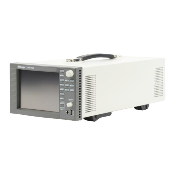
AMM768
Audio Multi-Channel Monitor
071-2171-01
Warning
The servicing instructions are for use by qualified
personnel only. To avoid personal injury, do not
perform any servicing unless you are qualified to
do so. Refer to all safety summaries prior to
performing service.
www.tektronix.com
Advertisement
Table of Contents
Troubleshooting

Related Manuals for Tektronix AMM768


Summary of Contents for Tektronix AMM768
-
Page 1: Service Manual
Service Manual AMM768 Audio Multi-Channel Monitor 071-2171-01 Warning The servicing instructions are for use by qualified personnel only. To avoid personal injury, do not perform any servicing unless you are qualified to do so. Refer to all safety summaries prior to performing service. - Page 2 Copyright © Tektronix. All rights reserved. Licensed software products are owned by Tektronix or its subsidiaries or suppliers, and are protected by national copyright laws and international treaty provisions. Tektronix products are covered by U.S. and foreign patents, issued and pending. Information in this publication supercedes that in all previously published material.
- Page 3 Warranty 2 Tektronix warrants that this product will be free from defects in materials and workmanship for a period of one (1) year from the date of shipment. If any such product proves defective during this warranty period, Tektronix, at its option, either will repair the defective product without charge for parts and labor, or will provide a replacement in exchange for the defective product.
-
Page 5: Table Of Contents
............3- - 2 AMM768 Audio Multi-Channel Monitor Service Manual... - Page 6 ..........5- - 2 AMM768 Audio Multi-Channel Monitor Service Manual...
- Page 7 ....... . . 4- -25 AMM768 Audio Multi-Channel Monitor Service Manual...
- Page 8 ....5- -9 Figure 5- -4: Analog audio breakout cable assembly ....5- -10 AMM768 Audio Multi-Channel Monitor Service Manual...
-
Page 9: General Safety Summary
Wear Eye Protection. Wear eye protection if exposure to high-intensity rays or laser radiation exists. Do Not Operate With Suspected Failures. If you suspect there is damage to this product, have it inspected by qualified service personnel. Do Not Operate in Wet/Damp Conditions. AMM768 Audio Multi-Channel Monitor Service Manual... - Page 10 CAUTION indicates a hazard to property including the product. Symbols on the Product. The following symbols may appear on the product: CAUTION WARNING Protective Ground Standby Refer to Manual High Voltage (Earth) Terminal AMM768 Audio Multi-Channel Monitor Service Manual...
-
Page 11: Service Safety Summary
Use Care When Servicing With Power On. Dangerous voltages or currents may exist in this product. Disconnect power, remove battery (if applicable), and disconnect test leads before removing protective panels, soldering, or replacing components. To avoid electric shock, do not touch exposed connections. AMM768 Audio Multi-Channel Monitor Service Manual... - Page 12 Service Safety Summary viii AMM768 Audio Multi-Channel Monitor Service Manual...
-
Page 13: Preface
Preface This manual supports servicing to the module level of the AMM768 Audio Multi-Channel Monitor, which processes audio signals for display on an internal XGA LCD. The instrument finds use as a monitor for broadcasting, production, and post-production environments. This manual explains how to troubleshoot and service the monitor to the module level. -
Page 14: Table I: Related Documentation
In depth operation and UI help AMM768 Audio Multi-Channel Procedure for checking perfor- Monitor Specifications and Perfor- mance and list of specifications mance Verification AMM768 Audio Multi-Channel Programmers command reference Monitor Master Information Base for controlling the audio monitor AMM768 Audio Multi-Channel Monitor Service Manual... -
Page 15: Introduction
Introduction... -
Page 17: Service Strategy
Documents CD that ships with the product. See Related Manuals on page ix. Options and Accessories The lists of options and accessories for this product are found in the AMM768 Audio Multi-Channel Monitor Quick Start User Manual that ships with the product. -
Page 18: Hardware Installation
Introduction For a complete list of options, refer to the AMM768 Audio Multi-Channel Monitor Quick Start User Manual. Hardware Installation The audio monitor is shipped in a wrap- -around chassis that covers the instru- ment bottom and two sides. A cover is installed on the chassis, and the rear panel is made up of the module rear panel and a removable blank panel. -
Page 19: Power-Down Procedure
Standby - - The instrument can be placed in a low-power standby mode by pressing the Main button and then touch the Standby soft key. This can also save the current instrument state as the Power Up Preset if the instrument is configured for that. 1- 3 AMM768 Audio Multi-Channel Monitor Service Manual... - Page 20 Introduction 1- 4 AMM768 Audio Multi-Channel Monitor Service Manual...
-
Page 21: Theory Of Operation
Theory of Operation... -
Page 23: Serial Digital Input Processing
Theory of Operation The AMM768 is a modular audio monitor. It can be configured, with options, to accept inputs for digital only or analog audio capability. With Option SDI embedded audio may be monitored and the digital SD or HD video picture may be displayed. -
Page 24: Figure 2- 1: Main Block Diagram
LTC Input Ground Closure I/O Interposer PLD and Memory Front Panel Core and Buttons & Knobs Peripherals Power Ethernet 10.100 Supply Touch Screen Ethernet MAC/PHY Main Board Figure 2- 1: Main block diagram 2- 2 AMM768 Audio Multi-Channel Monitor Service Manual... -
Page 25: Control Processor
Audio board for processing. Control Processor The control processor is in charge of all the operational modes in the instrument. It draws the audio bars, communicates with the front panel through SPI 2- 3 AMM768 Audio Multi-Channel Monitor Service Manual... -
Page 26: Ltc
All audio versions have the same basic processing engine. This uses an FPGA to route the audio input into two DSP chips, whose main function is to calculate the peak values for the selected meter ballistics (response characteristics). 2- 4 AMM768 Audio Multi-Channel Monitor Service Manual... -
Page 27: Fan Control
Power Supply and Distribution The power supply has a universal AC input, enabling it to accommodate 100 to 240 VAC without any user range switching. The output is 5 VDC. Circuits 2- 5 AMM768 Audio Multi-Channel Monitor Service Manual... - Page 28 Fuses on the Primary supply 5 V output protect the main board. The secondary supplies and their tolerances are specified in the troubleshooting section. The location of the supply test points is shown in Maintenance section. 2- 6 AMM768 Audio Multi-Channel Monitor Service Manual...
-
Page 29: Adjustment Procedures
Adjustment Procedures... -
Page 31: Adjustments
60 Hz scan rate AES Audio Signal Generator 48 kHz, 24 bit word length signals Rohde & Schwarz UPL06 Opt B22, B29 or UPV Opt B2, or Tektronix AM700 and AM70. Analog Audio Signal Generator Rohde & Schwarz UPL06 Opt B22, B29 or... -
Page 32: Procedures
10. Touch the Config soft key, and then the Diagnostics soft key. 11. Touch the Calibration soft key, and then the Analog PixMon soft key. 12. Read the on-screen dialog, and touch OK. 13. Touch the RGB/YUV soft key to begin the adjustment. 3- 2 AMM768 Audio Multi-Channel Monitor Service Manual... - Page 33 5. The Calibrate Audio dialog opens. Follow the on-screen instructions. 6. Repeat for each of the Analog Audio channels. This ends the adjustment procedure. To complete the process you should now perform a complete Performance Verification. 3- 3 AMM768 Audio Multi-Channel Monitor Service Manual...
- Page 34 Adjustments 3- 4 AMM768 Audio Multi-Channel Monitor Service Manual...
-
Page 35: Maintenance
Maintenance... -
Page 37: General Maintenance
CAUTION. Static discharge can damage any semiconductor component in the AMM768 Audio monitor. When performing any service that requires internal access to the AMM768 Audio monitor, adhere to the following precautions to avoid damaging internal modules and their components due to electrostatic discharge (ESD). -
Page 38: Inspection And Cleaning
Inspection and Cleaning Inspection and Cleaning describes how to inspect for dirt and damage. It also describes how to clean the exterior and interior of the AMM768 Audio monitor. Inspection and cleaning are done as preventive maintenance. Preventive maintenance, when done regularly, may prevent AMM768 Audio monitor malfunction and enhance its reliability. -
Page 39: Table 4- 1: External Inspection Check List
Dirty Clean with glass cleaner Inspection — Interior. To access the inside of the AMM768 Audio monitor for inspection and cleaning, you will need to remove the top cover. Inspect the internal portions of the AMM768 Audio monitor for damage and wear, using Table 4- -2 as a guide. -
Page 40: Table 4- 2: Internal Inspection Check List
STOP. If, after doing steps 1 and 2, a module is clean upon inspection, skip the remaining steps. 3. If steps 1 and 2 do not remove all the dust or dirt, the AMM768 Audio monitor may be spray washed using a solution of 75% isopropyl alcohol by doing steps 4 through 6. -
Page 41: Troubleshooting
Unknown Problem section in the Symptoms and Causes table. To properly test a AMM768 Audio monitor you must have appropriate signal sources. Depending on what portion of the instrument you are testing, this might include Serial Digital Video, Analog Audio, or Digital Audio. In some cases, you may also need receivers or an oscilloscope to check outputs. -
Page 42: Required Equipment
H Analog Audio, for Options AD, DD, and DDE H Dolby Decoder module, for Option DDE Required Equipment Troubleshooting the AMM768 will require the same test equipment that is listed for the Adjustment Procedure. See Table 3- -1, on page 3- -1. 4- 6... -
Page 43: Table 4- 3: Symptoms And Causes
Run Advanced Diagnostics and look for other information Diagnostic log shows Fail on any of these Review messages in diagnostic log. If the AMM768 Audio monitor also fails other tests as Advanced Diagnostics: well, then suspect Main board and perform the primary and secondary power supply tests. - Page 44 Main board and perform the primary and secondary power supply tests. H Lissajous Bus If only this test fails, then perform the Isolating Advanced Diagnostic Lissajous Errors procedure to isolate the problem to Main or Audio board. 4- 8 AMM768 Audio Multi-Channel Monitor Service Manual...
-
Page 45: Detailed Troubleshooting Procedures
Detailed Troubleshooting Procedures The following tests should be run as indicated in the Symptom and Causes table above. The procedures check for specific problems or will help you isolate a 4- 9 AMM768 Audio Multi-Channel Monitor Service Manual... -
Page 46: General Checks
R864 on the Main board, and use the oscilloscope to look for a 3.3 V square wave on the tachometer feedback line. Replace the fan if the pull up is intact but there is no signal on the tachometer line. 4- 10 AMM768 Audio Multi-Channel Monitor Service Manual... -
Page 47: Primary Power Supply Tests 4
This section describes methods for verifying the proper operation of the Tests AMM768 Audio monitor primary power supply. WARNING. Some parts of this test may require removing the insulating safety shield. To avoid personal injury, be careful not to contact the circuitry while the shield is removed. -
Page 48: Table 4- 4: Main Board Secondary Supplies
62 pin DSUB connector is mounted. The test points are available, with the board installed, along the top front edge of the board at the location specified in Figure 4- -3 on page 4- -21. 4- 12 AMM768 Audio Multi-Channel Monitor Service Manual... -
Page 49: Front Panel Button And Touchscreen Troubleshooting
1. Connect an external XGA monitor to the “Display” output on the rear of the instrument. 2. Cycle the power and watch the external monitor. If the monitor does not display the boot up messages and normal operational screen replace the Main board. 4- 13 AMM768 Audio Multi-Channel Monitor Service Manual... -
Page 50: Audio Post Failure
If any errors are found, perform the following procedure to narrow the problem to either the Audio board, the Main board, or the connection between them. 4- 14 AMM768 Audio Multi-Channel Monitor Service Manual... - Page 51 Probe pin B21 on the Audio board connector J641 during the boot sequence. If the signal does not toggle, replace the Audio board; otherwise, replace the Main board. If all of these steps pass, replace the Audio board. 4- 15 AMM768 Audio Multi-Channel Monitor Service Manual...
-
Page 52: Run Advanced Diagnostics
Pass/Fail tests, a lower section which shows SDI and Video bus activity, and, finally, narrow YRGB ramps at the very top and bottom to look for missing bits on the display interconnect. 4- 16 AMM768 Audio Multi-Channel Monitor Service Manual... -
Page 53: Table 4- 7: Advanced Diagnostic Measurements
25.1850 MHz Audio PLL 1 12.2780 MHz 12.2980 MHz Audio PLL 2 12.2780 MHz 12.2980 MHz HSYNC PW 20.4 s 20.8 s VSYNC PW 18974.9 s 19174.9 s Lissajous 61.3900 MHz 61.4900 MHz 4- 17 AMM768 Audio Multi-Channel Monitor Service Manual... -
Page 54: Isolating Advanced Diagnostic Lissajous Errors
Just verify that the signal is toggling and is ~3 V p- - p c. If either signal looks bad at J641 the Audio board most likely has a failure, otherwise replace the Main board. 4- 18 AMM768 Audio Multi-Channel Monitor Service Manual... -
Page 55: Figure 4- 1: Main Board Power Supply Test Points And Leds
General Maintenance DS231 DS232 F221, F222, F223 F231, F232, F233, F234 DS321 DS761 Secondary Power Supply Test Points DS861 R864 Figure 4- 1: Main board power supply test points and LEDs 4- 19 AMM768 Audio Multi-Channel Monitor Service Manual... -
Page 56: Figure 4- 2: Audio Main Board Power Supply Test Point Locations
General Maintenance J641 DS511 Secondary Power Supply Test Points Figure 4- 2: Audio Main board power supply test point locations 4- 20 AMM768 Audio Multi-Channel Monitor Service Manual... -
Page 57: Figure 4- 3: Analog Audio Board Power Supply Test Point Locations
General Maintenance Secondary Power Supply Test Points Figure 4- 3: Analog Audio board power supply test point locations 4- 21 AMM768 Audio Multi-Channel Monitor Service Manual... - Page 58 General Maintenance 4- 22 AMM768 Audio Multi-Channel Monitor Service Manual...
-
Page 59: Removal And Replacement Procedures
Equipment Required. Most modules in the instrument can be removed with a screwdriver handle mounted with a size T-10, TorxR screwdriver tip. All equipment required to remove and reinstall the modules is listed in Table 4- -8. 4- 23 AMM768 Audio Multi-Channel Monitor Service Manual... -
Page 60: Table 4- 8: Tools Required For Module Removal
Audio board BNCs Soldering iron (15 W) Used for replacing Main board fuses Standard tool Long nose pliers Used to compress connector lock Standard tool tabs, and to align touch panel connector 4- 24 AMM768 Audio Multi-Channel Monitor Service Manual... -
Page 61: Module Removal
Rear panel The rear panel is formed by the chassis, the audio module rear panel, and one blank panel, which are bolted together (see Figure 4- -4). 4- 25 AMM768 Audio Multi-Channel Monitor Service Manual... -
Page 62: Mezzanine Board
1. Unsnap the spring clips at each end of the option DDE circuit board. 2. Swing the top of the DDE board away from the Audio Main board. 3. Lift the option DDE board out of the instrument. 4- 26 AMM768 Audio Multi-Channel Monitor Service Manual... -
Page 63: Power Supply
7. Disconnect the power cable from J2 on the Power Supply. 8. Remove the two T-15 screws securing the Power Supply to the shield. 9. Lift the Power Supply out of the shield. 4- 27 AMM768 Audio Multi-Channel Monitor Service Manual... -
Page 64: Fan Assembly
6. Use a spudger or other tool to pry the bezel clips away from the bracket and then pull the bezel away, leading the front panel cable through the cutout in the bracket. 4- 28 AMM768 Audio Multi-Channel Monitor Service Manual... -
Page 65: Figure 4- 5: Front Panel Disassembly
11. When reassembling, make sure to route the backlight cables as noted in step 9, behind the Front Panel standoffs and clear of the cutout for the USB/Headphone connectors. 4- 29 AMM768 Audio Multi-Channel Monitor Service Manual... - Page 66 Removal and Replacement Procedures 4- 30 AMM768 Audio Multi-Channel Monitor Service Manual...
-
Page 67: Repackaging Instructions
When repacking the instrument for shipment, use the original packaging. If the packaging is unavailable or unfit for use, contact your local Tektronix representa- tive to obtain new packaging. Refer to Contacting Tektronix on the back of the Title page for the mailing address, the email address, and phone number. - Page 68 Repackaging Instructions 4- 32 AMM768 Audio Multi-Channel Monitor Service Manual...
-
Page 69: Replaceable Parts
Replaceable Parts... -
Page 71: Parts Ordering Information
Replaceable Parts This section contains a list of the replaceable modules for the AMM768 Audio Multi- -Channel Monitor. Use this list to identify and order replacement parts. Note that not all parts listed in this section are present on every model. The parts present will depend on the model and options installed. -
Page 72: Using The Replaceable Parts Lists
Using the Replaceable Parts Lists This section contains lists of the mechanical and/or electrical components that are replaceable for the AMM768 Audio Multi- -Channel Monitor. Use this list to identify and order replacement parts. The following table describes each column in the parts list. - Page 73 THD EXT 4- - 40 131- - 7582- - 00 CONN,DSUB; PCB;FEMALE,RTANG,DUAL STACKED,15 POS HD LOWER,9 POS UP- PER,SAFETY CONTROLLED 211- - 0722- - 00 SCREW,MACHINE; 6- - 32 X 0.250,PNH,STL,CDPL,T- - 15 TORX DR 5- 3 AMM768 Audio Multi-Channel Monitor Service Manual...
- Page 74 211- - 0722- - 00 SCREW,MACHINE; 6- - 32 X 0.250,PNH,STL,CDPL,T- - 15 TORX DR (USED WITH WFM7F02 PORTABLE CASE ONLY) * Quantity will vary depending on instrument model and installed options. 5- 4 AMM768 Audio Multi-Channel Monitor Service Manual...
-
Page 75: Figure 5- 1: Circuit Boards And Connectors
Replaceable Parts J130 J631 To J16 To J14 Green with yellow stripe GND Lug Ground lug Brown Blue Figure 5- 1: Circuit boards and connectors 5- 5 AMM768 Audio Multi-Channel Monitor Service Manual... - Page 76 PB- - FREE;ENCODER; DIGITAL CONTACTING ENCODER, 24 CPR, NON- - DETENTED, 6 MM DIA SHAFT, 17.5 MM LENGTH SHAFT, 12 MM BODY SIZE, TOP MOUNT; RE0123 260- - 2846- - 00 SWITCH, KEYPAD; ELASTOMERIC, SILICONE RUBBER;FRONT PANEL, AMM768 426- - 2621- - 00 FRAME; FRONT BEZEL,PC/ABS,TV GRAY,SAFETY CONTROLLED 335- - 1767- - 00 LABEL FRONT PANEL;...
-
Page 77: Figure 5- 2: Chassis Components
To J27 through Slot B To CN2 through Slot D To remove the flourescent tube, press down on the black pastic tab while sliding the tube out. Figure 5- 2: Chassis components 5- 7 AMM768 Audio Multi-Channel Monitor Service Manual... - Page 78 Tektronix part Serial no. Serial no. number number effective discont’d Name & description 5- - 3- - 1 159- - 5022- - 00 FUSE; 5.0A,125V;FAST BLOW,0.1 X 0.1 X 0.24,UL REG,CSA CERT;451005,SAFETY CONTROLLED 5- 8 AMM768 Audio Multi-Channel Monitor Service Manual...
-
Page 79: Figure 5- 3: Main Board Replaceable Components
Replaceable Parts F231, F232, F221, F233, F222, F234 F223 Figure 5- 3: Main board replaceable components 5- 9 AMM768 Audio Multi-Channel Monitor Service Manual... -
Page 80: Figure 5- 4: Analog Audio Breakout Cable Assembly
Note: Optional Accessory 5-4-2 200-4804-00 COVER; SHIELD,ELEC CONN,37 POS DSUB,ZINC 5-4-3 131-0422-00 CONN,DSUB; SLDR CUP/PNL,;MALE,STR,37 POS,0.112 CTR,0.186 H X 0.126 TAIL,0.125 DIA THRU MTG;,, Figure 5- 4: Analog audio breakout cable assembly 5- 10 AMM768 Audio Multi-Channel Monitor Service Manual... - Page 81 MANUAL,WAVEFORM MONITORS RELEASE NOTES; AMM768 071- - 2174- - xx MANUAL,WAVEFORM MONITORS SPECIFICATIONS & PERFORMANCE VERIFICATION TECHNICAL REFERENCE; AMM768 063- - 4035- - xx DATA SHEET; WAVEFORM MONITORS DOCUMENTATION CD- - ROM; AMM768 See Description CABLE ASSY, POWER: OPTION COUNTRY N.
- Page 82 Replaceable Parts 5- 12 AMM768 Audio Multi-Channel Monitor Service Manual...
Need help?
Do you have a question about the AMM768 and is the answer not in the manual?
Questions and answers