Table of Contents

Related Manuals for Mitsubishi Electric PAC-IF072B-E


Summarization of Contents
Safety Precautions
1.1 Before Installation (Environment)
Guidelines for selecting an appropriate installation environment to prevent damage or shock.
1.2 Before Installation or Relocation
Precautions for handling and moving the unit safely during installation or relocation.
1.3 Before Electric Work
Essential steps and precautions before commencing electrical work to ensure safety.
1.4 Before Starting Test Run
Procedures and settings required before performing the initial test run of the unit.
1.5 Electric Booster and Immersion Heaters
Warnings and requirements regarding the use of electric boosters and immersion heaters.
Installing the FTC Unit
2.1 Check the Parts
List and identification of components supplied with the FTC unit for installation.
2.2 Choosing the FTC Unit Installation Location
Guidelines for selecting an optimal installation site for the FTC unit to ensure proper function and safety.
2.3 Installing the FTC Unit
Step-by-step instructions for physically mounting and securing the FTC unit during installation.
System
3.1 First Step (Electrical Work)
Initial electrical considerations and system diagrams for connecting the FTC unit.
3.2 Second Step (Outdoor Unit Type)
Details on different outdoor unit types and their integration within the system.
3.3 Third Step (Functions Setting)
Configuration options for various system functions, including DHW and heating modes.
3.4 Fourth Step (Functions Setting)
Detailed requirements and specifications for system components and their integration.
3.5 Local System
Various system layouts and configurations for different local applications and zone controls.
3.6 Minimum Amount of Water Required
Specifies the minimum water volume needed for space heating and cooling circuits based on unit type.
3.7 Energy Monitor
Describes how to monitor accumulated energy consumption and delivered heat energy via the remote controller.
Electrical Work
4.1 Electrical Connection
Detailed instructions and diagrams for making electrical connections for the FTC unit.
4.1 Electrical Connection - Options
Instructions for different power supply options for the FTC unit, including independent power sources.
4.2 Connecting the Main Remote Controller
Procedures for connecting and installing the main remote controller to the FTC unit.
4.2 Connecting the Main Remote Controller - Installation Details
Further steps and precautions for installing the main remote controller, including case fitting and cable management.
4.2 Connecting the Main Remote Controller - Final Assembly & Disassembly
Instructions for attaching the top case and front cover, and how to disassemble them.
4.3 Main Remote Controller Options
Explains various configurations for the main remote controller and its integration with other sensors.
4.3 Main Remote Controller Options - 2-Zone Control
Details on 2-zone temperature control options involving remote controllers and thermostats.
4.4 Connecting the Thermistor Cables
Instructions for connecting various thermistor cables to the FTC unit, including placement and necessity.
4.4.5 Thermistor Position and Necessity
Table and diagrams showing the required positions and necessity of various thermistors for different unit types.
4.5 Connecting Inputs/Outputs
Details on connecting various input/output signals, auxiliary settings, and wiring specifications.
4.5 Connecting Inputs/Outputs - Thermistor and Output Details
Further details on thermistor inputs and output connections, including specifications and diagrams.
4.6 Wiring for Heater
Specific wiring diagrams and precautions for connecting booster and immersion heaters.
4.7 Wiring for 2-Zone Temperature Control
Instructions for wiring and configuring a 2-zone temperature control system.
4.8 2-Zone Valve ON/OFF Control
Details on implementing a 2-zone control using 2-way valves and room thermostat connections.
4.10 Installation Procedure for DHW Tank
Step-by-step guide for installing the DHW tank, including valve and thermistor connections.
4.11 Using SD Memory Card
Instructions and precautions for using SD memory cards for settings and data logging.
Dip Switch Setting
5.1 DIP Switch Functions
Details on the function and settings of the DIP switches located on the FTC printed circuit board.
5.2 Outdoor Unit Type
Configuration of DIP switches to specify the type of outdoor unit and maximum water temperature.
5.3 Functions setting
DIP switch settings to enable or disable various system functions like boilers, DHW tanks, heaters, and mixing tanks.
5.4 Operation setting
DIP switch configurations for remote controller, thermostat logic, cooling mode, and heating mode.
5.5 Emergency mode (Heater only operation)
Procedures for activating emergency modes for heater-only operation in case of system failures.
5.6 Emergency mode (Boiler operation)
Procedures for activating emergency modes for boiler operation in case of system failures.
5.7 Indoor unit only operation
Instructions for operating the unit using only the indoor electric heater during installation work.
Before Test Run
6.1 Check
Essential checks and tests to perform after installation and before initiating the unit's test run.
6.2 Self-Check
How to identify, understand, and reset system errors displayed during self-check.
Main Remote Controller Operation
7.1 Safety Precautions
General safety guidelines for users regarding the installation and operation of the remote controller.
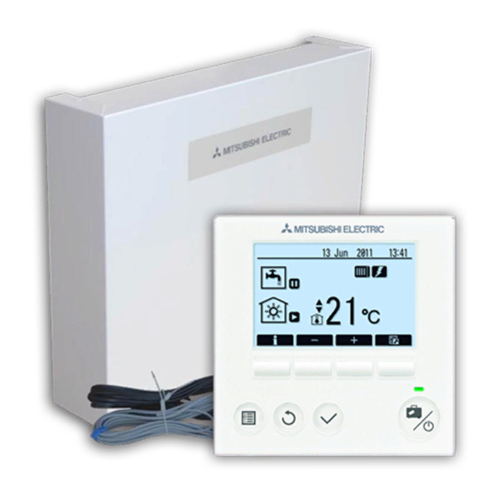
7.2 Main Remote Controller
Explanation of the main remote controller's parts, functions, and on-screen icons.
[Initial setting wizard]
Guide to initial setup procedures and accessing main settings via the remote controller menu.
Auxiliary settings
Detailed breakdown of auxiliary settings, heat source controls, operation parameters, and smart grid functions.
DHW mode settings
Configuration options for Domestic Hot Water (DHW) and Legionella prevention modes, including Eco mode.
Legionella Prevention Mode settings (LP mode)
Detailed settings for the Legionella Prevention Mode, including temperature, frequency, and duration.
[Service] Menu
Accessing the service menu, setting a password, and performing manual operations for system components.
Heating operation
Configuring heating operation parameters like flow temperature and freeze stat function for optimal performance.
[Floor dry up function]
Configuring the floor dry-up function and energy monitoring settings for the system.
[Password protection]
Procedures for securing the service menu with a password and resetting the system to factory defaults.
Troubleshooting
Troubleshooting by Inferior Phenomena
Lists common fault symptoms, their possible causes, and solutions for diagnosing and resolving issues across various system components.
Troubleshooting Fault Symptoms
Continues the troubleshooting guide, covering issues like LED status, water temperature, and heating system performance.
Troubleshooting System Anomalies
Addresses further troubleshooting scenarios including pressure relief valve issues, pump noise, and cooling system performance.
Multiple Outdoor Units Control
9.1 Wiring for Multiple Outdoor Units Control
Requirements and wiring guidelines for connecting multiple outdoor units to a single system.
9.2 Pipe Work and System Examples
Guidance on pipework and system configurations for multiple outdoor units, including DHW and boiler integration.
9.3 Electrical Connection
Electrical connection procedures for main units, sub units, independent power sources, and Hydrobox.
9.4 Main Remote Controller Wiring
Instructions for wiring the main remote controller and daisy-chaining units in a multi-outdoor system.
9.5 Connecting Thermistor Cables for Sub Controller
Connecting thermistors to the FTC (Sub) controller for accurate temperature monitoring.
9.6 Dip Switch Functions
Configuring DIP switches on outdoor units, main, and sub units for multi-unit and DHW operations.
9.7 Connecting Inputs/Outputs for Sub Controller
Instructions for connecting inputs, outputs, thermistors, and wiring specifications for sub controllers.
PAC-SIF051B-E Controller Connections
Detailed connection diagrams and specifications for the PAC-SIF051B-E controller, including inputs, outputs, and thermistors.
Hydrobox Controller Connections
Connection details for the Hydrobox controller, including signal inputs, thermistors, outputs, and wiring specifications.
Troubleshooting Multiple Outdoor Unit Systems
Common issues and solutions for multi-unit control systems, focusing on remote controller and communication failures.
Supplementary Information
10.1 Refrigerant Collecting (Pumpdown)
Reference for refrigerant collection procedures for split model systems.
10.2 Back-up Operation of Boiler
Information on setting up and configuring the boiler for back-up heating operation.
Local Application Factors
Heat Exchanger and Contamination Maintenance
Specifications for heat exchanger performance, pressure, and contamination maintenance requirements.
Water Quality, Pipework, and Thermistor Placement
Guidelines on water quality, pipework, thermistor placement, and safety warnings.
R32 Refrigerant and System Component Requirements
Safety notices and specific requirements for R32 refrigerant, pressure sensors, flow sensors, and pressure relief valves.
Need help?
Do you have a question about the PAC-IF072B-E and is the answer not in the manual?
Questions and answers