Table of Contents
Advertisement
Instruction Manual
D103221X012
Fisher
D3 FloPro Control Valve
™
Contents
. . . . . . . . . . . . . . . . . . . . . . . . . . . . . . . . .
. . . . . . . . . . . . . . . . . . . . . . . . . . . . .
. . . . . . . . . . . . . . . . . . . . . . . . . . . . . . . . .
. . . . . . . . . . . . . . . . . . . . . . . . . . . . . . .
. . . . . . . . . . . . . . . . . . . . . . . . .
. . . . . . . . . . . . . . . . . . . . . . . . . . . . . . . . . .
. . . . . . . . . . . . . . . . . . . . . . . . . . . . . . . . .
. . . . . . . . . . . . . . . . . . . . . . . .
. . . . . . . . . . . . . . . . . . . . . . . . . . . . . . .
. . . . . . . . . . . . . . . . . . . . . . . . . . . . . . . . . . .
. . . . . . . . . . . . . . . . . . . . . . . . . . . . . . . . . . .
Introduction
Scope of Manual
This instruction manual provides installation, maintenance, and parts information for the Fisher D3 FloPro control
valve and actuator.
Do not install, operate, or maintain D3 FloPro valves without being fully trained and qualified in valve, actuator, and
accessory installation, operation, and maintenance. To avoid personal injury or property damage, it is important to
carefully read, understand, and follow all the contents of this manual, including all safety cautions and warnings. If you
have any questions about these instructions, contact your
proceeding.
Description
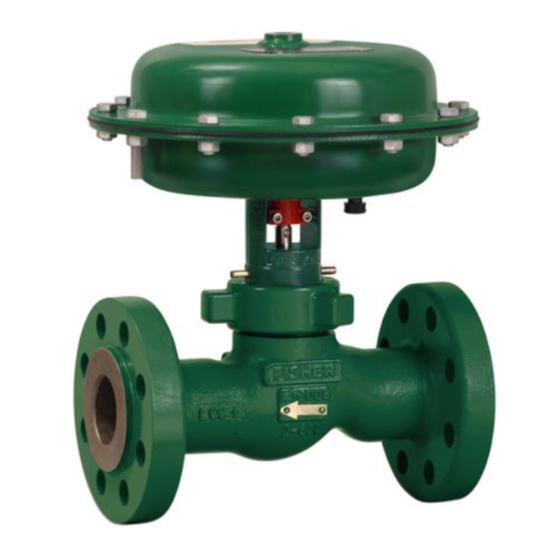
The D3 FloPro control valve (figure 1) is a compact, rugged valve designed for on-off control of a variety of fluids at
pressures up to 155 bar (2250 psig). This valve is ideal for use as a dump valve on gas separators and scrubbers. It is
also well suited for other high pressure applications in natural gas production, compression, and processing. NPS 1 and
NPS 2 D3 FloPro control valves are available in CL900 NPT end connections and CL600 raised face flanged end
connections.
www.Fisher.com
. . . . . . . . . . . .
. . . . . . . . . .
. . . . . . . . . . . . . . . . . . . . . . .
. . . . . . . . . . . . . . . . . . . .
Figure 1. Fisher D3 FloPro Control Valve
NPS 2 RF Flanged End Connection
1
1
1
2
3
3
4
4
5
10
12
20
20
23
23
W9249
Emerson sales office
D3 FloPro Valve
or Local Business Partner before
June 2017
Advertisement
Table of Contents

Related Manuals for Emerson Fisher D3


Summary of Contents for Emerson Fisher D3
-
Page 1: Table Of Contents
Introduction Scope of Manual This instruction manual provides installation, maintenance, and parts information for the Fisher D3 FloPro control valve and actuator. Do not install, operate, or maintain D3 FloPro valves without being fully trained and qualified in valve, actuator, and accessory installation, operation, and maintenance. -
Page 2: Specifications
Table 1 lists specifications for the D3 FloPro control valve. Some of the specifications for a given control valve as it originally comes from the factory are stamped on a nameplate located on the upper diaphragm casing. Table 2. Fisher D3 Maximum Shutoff Pressure Drops MAXIMUM nP (PSI) PER PORT SIZE (INCH) -
Page 3: Educational Services
0.375, 0.75, 1 0.375, 0.75, 1 X = Available construction. Educational Services For information on available courses for Fisher D3 valves, as well as a variety of other products, contact: Emerson Automation Solutions Educational Services - Registration Phone: 1-641-754-3771 or 1-800-338-8158 E-mail: education@emerson.com... -
Page 4: Setting The Valve Flopro Flow Adjuster
Instruction Manual D3 FloPro Valve June 2017 D103221X012 4. Install the valve following local and national piping codes when they apply to the application. For screwed connections, treat the external pipe threads with a good grade pipe compound. For flanged connections, use suitable gaskets between valve and pipeline flanges. -
Page 5: Valve Plug And Seat Ring Maintenance
Instruction Manual D3 FloPro Valve D103221X012 June 2017 Valve parts are subject to normal wear and must be inspected and replaced as necessary. The frequency of inspection and maintenance depends on the severity of the service conditions. WARNING Avoid personal injury from sudden release of process pressure or bursting of parts. Before performing any maintenance operations: D Do not remove the actuator from the valve while the valve is still pressurized. - Page 6 Instruction Manual D3 FloPro Valve June 2017 D103221X012 to unscrew the bonnet nut. The bonnet nut will contact the spring pins (or pipe plugs) (key 6, figures 7 or 8) and jack the bonnet out of the valve. Carefully lift the actuator assembly from the valve body. WARNING The spring pins/pipe plugs (key 6) must always be in place during valve operation.
- Page 7 Instruction Manual D3 FloPro Valve D103221X012 June 2017 6. Break the bonnet nut (key 5) loose with a hammer. Continue turning the bonnet nut by using a hammer or a large adjustable wrench, tightened around one ear of the bonnet nut. If the bonnet (key 7) is stuck in the valve, continue to unscrew the bonnet nut.
- Page 8 Instruction Manual D3 FloPro Valve June 2017 D103221X012 Figure 3. Packing and Belleville Spring Stacking Order UPPER PACKING SPACER (KEY 12) ANTI‐EXTRUSION WASHER (KEY 10) FEMALE PACKING ADAPTER (KEY 11) PACKING RING (KEY 11) MALE PACKING ADAPTER (KEY 11) ANTI‐EXTRUSION WASHER (KEY 10) LOWER PACKING SPACER (KEY 12)
- Page 9 Instruction Manual D3 FloPro Valve D103221X012 June 2017 Figure 5. Lubrication Locations on Packing FEMALE PACKING ADAPTER LUBRICATE WITH 3mm (1/8 INCH BEAD) OF SUPPLIED HIGH PACKING RING PERFORMANCE FLUORINATED GREASE (KEY 44) LUBRICATE WITH 3mm (1/8 INCH MALE PACKING ADAPTER BEAD) OF SUPPLIED HIGH PERFORMANCE FLUORINATED GREASE 6.
-
Page 10: Packing Maintenance
Instruction Manual D3 FloPro Valve June 2017 D103221X012 9. Lubricate the bonnet O‐ring (key 4) with lithium grease and install on the bonnet. 10. Apply anti‐seize lubricant to the threads on the valve body and bonnet nut (key 5) and the contact surfaces of the bonnet and bonnet nut flange. - Page 11 Instruction Manual D3 FloPro Valve D103221X012 June 2017 2. Use the lower packing spacer (key 12) and a tube to push the upper anti‐extrusion washer (key 10) into place. Using the lower packing spacer in this manner will ensure the upper anti‐extrusion washer is fully seated and flat when installed in the packing bore.
-
Page 12: Servicing The Actuator
Instruction Manual D3 FloPro Valve June 2017 D103221X012 4. Apply a 3mm (1/8 inch) bead of the supplied high performance fluorinated grease (key 44) around the groove of the female packing adaptor as shown in figure 5 and install over the valve stem (key 16). 5. - Page 13 Instruction Manual D3 FloPro Valve D103221X012 June 2017 2. Remove the ten short actuator casing cap screws (key 29). 3. Remove the two long actuator casing cap screws (key 31) by alternating between them as you loosen them. Keep the upper casing (key 32) level during this procedure. 4.
- Page 14 Instruction Manual D3 FloPro Valve June 2017 D103221X012 Inspect all parts for wear or damage during disassembly. Replace any worn or damaged parts with genuine Fisher replacement parts. If the diaphragm is replaced, a new diaphragm O‐ring should also be installed. 1.
- Page 15 Instruction Manual D3 FloPro Valve D103221X012 June 2017 Figure 6. Spring Locations As Seen From Above Lower Actuator Casing 3 SPRINGS 2 SPRINGS 6 SPRINGS 15. Remove the stem O‐ring (key 25) and the bonnet bushing (key 18). 16. If the hammer nut needs to be removed from the bonnet, the spring pins (or pipe plugs) (key 6, figures 7 or 8) can be removed with locking pliers.
- Page 16 Instruction Manual D3 FloPro Valve June 2017 D103221X012 2. Lubricate the stem O‐ring (key 25) with lithium grease and install in the bonnet (key 7). 3. Press the bonnet bushing (key 18) with the slots upward into the upper hole in the bonnet. The bonnet bushing is installed correctly when it snaps into place.
- Page 17 Instruction Manual D3 FloPro Valve D103221X012 June 2017 CAUTION Avoid possible product damage which may affect proper operation of the diaphragm. Ensure the washer is aligned with the hole in the diaphragm so the washer does not cut the diaphragm. 23.
- Page 18 Instruction Manual D3 FloPro Valve June 2017 D103221X012 Make sure all parts are clean and in good condition before starting assembly. There should be no burrs or sharp edges on any threads or surfaces that might cut or damage soft parts in the valve assembly. CAUTION The threads on factory‐produced valve stems have been specially machined to avoid O‐ring, bushing, or packing damage during trim maintenance.
- Page 19 Instruction Manual D3 FloPro Valve D103221X012 June 2017 13. Install the male packing adaptor, lower anti‐extrusion washer (key 10), and lower packing spacer over the valve stem as shown in figure 3. 14. Firmly press all packing parts into the packing bore with a tube. 15.
-
Page 20: Changing Actuator Action
WARNING Use only genuine Fisher replacement parts. Components that are not supplied by Emerson Automation Solutions should not, under any circumstances, be used in any Fisher valve, because they may void your warranty, might adversely affect the performance of the valve, and could cause personal injury and property damage. - Page 21 Instruction Manual D3 FloPro Valve D103221X012 June 2017 Figure 7. Fisher D3 FloPro Valve Assembly (Spring‐to‐Close) VIEW B BELLEVILLE SPRING KEY 6 ALTERNATE PIPE PLUG VIEW A AND PACKING ARRANGEMENT CONSTRUCTION VIEW A SEE VIEW B FOR ALTERNATE CONSTRUCTION GE21319‐B...
- Page 22 Instruction Manual D3 FloPro Valve June 2017 D103221X012 Figure 8. Fisher D3 FloPro Valve Assembly (Spring‐to‐Open) VIEW B BELLEVILLE SPRING KEY 6 ALTERNATE PIPE PLUG VIEW A AND PACKING ARRANGEMENT CONSTRUCTION VIEW A SEE VIEW B FOR ALTER NATE CONSTRUCTION GE21338‐B...
-
Page 23: Parts Kits
Recommended spare parts are included in the Parts Kits shown at the Lower Casing top of this page. For additional information or for part numbers not Diaphragm Washer shown, contact your Emerson sales office or Local Business Partner. Diaphragm Diaphragm Plate Stem O‐ring... -
Page 24: D103221X012 June
Responsibility for proper selection, use, and maintenance of any product remains solely with the purchaser and end user. Fisher is a mark owned by one of the companies in the Emerson Automation Solutions business unit of Emerson Electric Co. Emerson Automation Solutions, Emerson, and the Emerson logo are trademarks and service marks of Emerson Electric Co.
Need help?
Do you have a question about the Fisher D3 and is the answer not in the manual?
Questions and answers