Table of Contents
Advertisement
Quick Links
Instruction Manual
D103031X012
Fisherr D2 FloPro Control Valve
Contents
. . . . . . . . . . . . . . . . . . . . . . . . . . . . . . . . .
. . . . . . . . . . . . . . . . . . . . . . . . . . . . .
. . . . . . . . . . . . . . . . . . . . . . . . . . . . . . . . .
. . . . . . . . . . . . . . . . . . . . . . . . . . . . . . .
. . . . . . . . . . . . . . . . . . . . . . . . . . . . . . . . . .
. . . . . . . . . . . . . . . . . . . . . . . . . . . . . . . . .
. . . . . . . . . . . . . . . . . . . . . . . . . . . . . . . . . . .
. . . . . . . . . . . . . . . . . . . . . . . . . . . . . . . . . . .
Introduction
Scope of Manual
This instruction manual provides installation, maintenance, and parts information for the NPS 1 Fisher D2 FloPro
control valve and actuator manufactured with lot numbers equal to and greater than 0410-xxxx.
See Appendix A for information on packing constructions manufactured with lot numbers less than 0410-xxxx.
Do not install, operate, or maintain a D2 FloPro control valve without being fully trained and qualified in valve,
actuator, and accessory installation, operation, and maintenance. To avoid personal injury or property damage, it is
important to carefully read, understand, and follow all the contents of this manual, including all safety cautions and
warnings. If you have any questions about these instructions, contact your Emerson Process Management sales office
before proceeding.
Description
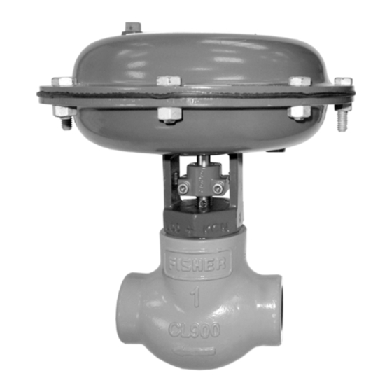
The D2 FloPro control valve (figure 1) is a compact, rugged valve designed for on-off control of a variety of fluids at
pressures up to 155 bar (2250 psig). This valve is ideal for use as a dump valve on gas separators and scrubbers. It is
also well suited for other high pressure applications in natural gas production, compression, and processing. The D2
FloPro valve has threaded end connections and is available in an NPS 1 globe style valve body.
www.Fisher.com
. . . . . . . . . . . . . .
. . . . . . . . . . . . . . .
. . . . . . . . . . . . . . . . . . . . . .
. . . . . . . . . . . . . . . . . . . . .
. . . . . . . . .
Figure 1. Fisher D2 FloPro Control Valve
1
1
1
2
3
4
4
5
6
7
14
14
17
W9235-1
D2 FloPro Valve
June 2011
Advertisement
Table of Contents

Related Manuals for Emerson Fisherr D2 FloPro


Summary of Contents for Emerson Fisherr D2 FloPro
-
Page 1: Table Of Contents
To avoid personal injury or property damage, it is important to carefully read, understand, and follow all the contents of this manual, including all safety cautions and warnings. If you have any questions about these instructions, contact your Emerson Process Management sales office before proceeding. -
Page 2: Specifications
Instruction Manual D2 FloPro Valve June 2011 D103031X012 Table 1. Specifications Valve Assembly Pressure Class Port Diameter 13 mm (0.5 inch) ASME B16.34 CL900 Maximum Travel Maximum Inlet Pressure and Temperature 13 mm (0.5 inch) 155 bar from -46 to 93C, and 150 bar at 149C. (2250 psig from —50 to 200F, and 2185 psig at Approximate Weight 300F) -
Page 3: Installation
Do not expose this valve to service conditions or variables other than those for which this valve is intended. If you are not sure what these conditions are, you should contact your Emerson Process Management sales office for more complete specifications. -
Page 4: Setting Valve Flopro Flow Adjuster
Instruction Manual D2 FloPro Valve June 2011 D103031X012 Figure 2. Flow Rate Adjustments FloPro TRAVEL INDICATOR SAFETY FLOW ADJUSTER VENT 0.25 INCH FLOW RATE 0.5 INCH FLOW RATE 0.375 INCH FLOW RATE Cv = 2 Cv = 6 Cv = 4 Fl = 0.65 Fl = 0.77 Fl = 0.706... -
Page 5: Maintenance
Instruction Manual D2 FloPro Valve D103031X012 June 2011 1. Remove the six short actuator casing cap screws (key 22) first. Once these have been removed from the actuator assembly, remove the two long actuator cap screws (key 30) by alternating between them as you loosen them, to keep the upper casing (key 21) level during this procedure. -
Page 6: Valve Trim Maintenance
Instruction Manual D2 FloPro Valve June 2011 D103031X012 WARNING Avoid personal injury from sudden release of process pressure. Before performing any maintenance operations: D Do not remove the actuator from the valve while the valve is still pressurized. D Always wear protective gloves, clothing, and eyewear when performing any maintenance operations to avoid personal injury. -
Page 7: Packing, Valve Trim, And Actuator Maintenance
Instruction Manual D2 FloPro Valve D103031X012 June 2011 WARNING Avoid personal injury from sudden release of process pressure. If the process media starts to escape from the safety vent (see figure 2) located in the bonnet neck of the valve body, STOP DISASSEMBLY IMMEDIATELY! The escape of process media indicates that the valve has NOT been isolated from the process media, or process pressure is trapped in the valve body. - Page 8 Instruction Manual D2 FloPro Valve June 2011 D103031X012 Figure 3. Fisher D2 FloPro Construction PRESSURE CONNECTION VALVE STEM SERRATIONS VISIBLE IN THE FLOW ADJUSTER WINDOW W9005-1 GLOBE STYLE AIR-TO-OPEN Key numbers are referenced in figures 6 and 7. Disassembly 1. Isolate the control valve from the line pressure, release pressure from both sides of the valve body, and drain the process media from both sides of the valve.
- Page 9 Instruction Manual D2 FloPro Valve D103031X012 June 2011 CAUTION The preceding step is intended to prevent damage to the valve plug (key 3) and seat ring (key 5) during the removal of the bonnet and actuator. 3. Unscrew the bonnet from the valve body. WARNING Avoid personal injury from sudden release of process pressure.
- Page 10 11. Clean and inspect the packing box wall to ensure that the packing surfaces are not damaged. If the surface condition is damaged, and cannot be improved by light sanding, replace the bonnet by contacting your Emerson Process Management sales office.
- Page 11 Instruction Manual D2 FloPro Valve D103031X012 June 2011 Figure 4. Packing and Belleville Spring Stacking Order ANTI-EXTRUSION WASHER (KEY 12) FEMALE PACKING ADAPTER (KEY 11) PACKING RING (KEY 11) MALE PACKING ADAPTER (KEY 11) ANTI-EXTRUSION UNTIGHTENED, WASHER (KEY 12) NOTE THE GAP PACKING SPACER (KEY 10)
- Page 12 Instruction Manual D2 FloPro Valve June 2011 D103031X012 5. Install the male packing adaptor, lower anti-extrusion washer (key 12), and packing spacer over the valve stem as shown in figure 4. 6. Firmly press all packing parts into the packing bore with a tube. 7.
- Page 13 Instruction Manual D2 FloPro Valve D103031X012 June 2011 WARNING Upon reassembly, ensure that no foreign material blocks the safety vent hole as shown in figure 2. If the safety vent hole is blocked or plugged, possible personal injury from the sudden release of process pressure during maintenance disassembly may occur.
-
Page 14: Parts Kits
Note Neither Emerson, Emerson Process Management, nor any of their affiliated entities assumes responsibility for the selection, use, or maintenance of any product. Responsibility for the selection, use, and maintenance of any product remains with the purchaser and end user. - Page 15 Instruction Manual D2 FloPro Valve D103031X012 June 2011 Figure 6. Fisher D2 FloPro Assembly–Air-to-Open 39B5892-M...
- Page 16 Instruction Manual D2 FloPro Valve June 2011 D103031X012 Figure 7. Fisher D2 FloPro Assembly–Air-to-Close 39B8450-M...
-
Page 17: Appendix A (Packing Constructions With Lot Numbers Less Than 0410-Xxxx)
Instruction Manual D2 FloPro Valve D103031X012 June 2011 Appendix A (Packing Constructions with Lot Numbers Less Than 0410) Appendix A provides information on packing constructions manufactured with lot numbers less than 0410-xxxx. Packing and Valve Trim Maintenance (Appendix A) Note The following maintenance procedures apply to both air-to-open and air-to-close actuator configurations, except as noted. - Page 18 Instruction Manual D2 FloPro Valve June 2011 D103031X012 and inspect the valve body gasket surface for damage. Visually inspect the valve body interior below the seat ring for erosion. Replace the valve body if necessary. To replace the seat ring, first install a new seat ring gasket. Install the new seat ring and tighten to 230 NSm (170 lbfSft).
- Page 19 11. Clean and inspect the packing box wall to ensure that the packing surfaces are not damaged. If the surface condition is damaged, and cannot be improved by light sanding, replace the bonnet by contacting your Emerson Process Management sales office.
- Page 20 Instruction Manual D2 FloPro Valve June 2011 D103031X012 Figure 9. Fisher D2 FloPro Construction (Appendix A) PRESSURE CONNECTION VALVE STEM SERRATIONS VISIBLE IN THE FLOW ADJUSTER WINDOW W9005-1 GLOBE STYLE AIR-TO-OPEN WARNING Upon reassembly, ensure that no foreign material blocks the safety vent hole as shown in figure 2. If the safety vent hole is blocked or plugged, possible personal injury from the sudden release of process pressure during maintenance disassembly may occur.
- Page 21 Note Neither Emerson, Emerson Process Management, nor any of their affiliated entities assumes responsibility for the selection, use, or maintenance of any product. Responsibility for the selection, use, and maintenance of any product remains with the purchaser and end user.
- Page 22 Instruction Manual D2 FloPro Valve June 2011 D103031X012 Figure 10. Fisher D2 FloPro Assembly–Air-to-Open (Appendix A) BELLEVILLE SPRING AND PACKING ARRANGEMENT APPLY LUB/ADHESIVE 39B5892-K...
- Page 23 Instruction Manual D2 FloPro Valve D103031X012 June 2011 Figure 11. Fisher D2 FloPro Assembly–Air-to-Close (Appendix A) BELLEVILLE SPRING AND PACKING ARRANGEMENT 39B8450-K APPLY LUB/ADHESIVE...
- Page 24 Fisher and ENVIRO-SEAL are marks owned by one of the companies in the Emerson Process Management business division of Emerson Electric Co. Emerson Process Management, Emerson, and the Emerson logo are trademarks and service marks of Emerson Electric Co. All other marks are the property of their respective owners.
Need help?
Do you have a question about the Fisherr D2 FloPro and is the answer not in the manual?
Questions and answers