Advertisement
SPECIFICATIONS:
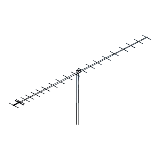
Model ......................................... 432-6WL
Frequency Range ....................... 420 To 440 MHz
*Gain .......................................... 18.04 dBi
Front to back .............................. 23 dB Typical
Beamwidth ............................... E=22° H=24°
Feed type ................................... Folded Dipole
Feed Impedance. ....................... 50 Ohms Unbalanced
Maximum VSWR ........................ 1.2:1 Typical
Input Connector .......................... "N" Female
FEATURES:
The 432-6WL is the ultimate antenna: computer and range optimized for very high gain and excellent pattern
across its bandwidth. It can be mounted vertically or horizontally and is also ideal for OSCAR, FM, LONG HAUL TROPO,
ETC. Its lightweight, yet sturdy, construction keeps the wind area low without compromising the 100 MPH wind survival
rating. We guarantee you will be impressed.
The heart of the 432-6WL is a unique Driven Element Module with superior weather resistance and power han-
dling abilities. The module is CNC machined from a solid aluminum block, features O-ring sealed connectors and internal
connections embedded in a special silicone gel that seals out weather and improves power handling. The Balun connect-
ors are triple-sealed to the coax. Other key mechanical and electrical parts are CNC machined from 6061-T6 aluminum
and all hardware except U-bolts is stainless steel.
The 432-6WL offers you uncompromising performance, enduring mechanical construction, and long term electri-
cal integrity. Where else but M
M2 Antenna Systems, Inc. 4402 N. Selland Ave. Fresno, CA 93722
M2 Antenna Systems, Inc.
Model No: 432-6WL
*Subtract 2.14 from dBi for dBd
2
.
Tel: (559) 432-8873 Fax: (559) 432-3059 Web: www.m2inc.com
©2015 M2 Antenna Systems Incoporated
Power Handling .......................... 1 kW
Boom Length / Dia ...................... 14' 6"' / 1"
Maximum Element Length .......... 13-7/8"
Turning Radius: .......................... 96"
Stacking Distance ....................... 65" High & 65" Wide
Mast Size .................................... 2" Nom.
Wind area / Survival ................... 0.85 Sq. Ft. / 100 MPH
Weight / Ship Wt. ........................ 4.6 Lbs. / 7 Lbs.
05/28/15
Rev.03
Advertisement
Table of Contents

Related Manuals for M2 Antenna Systems 432-6WL


Summary of Contents for M2 Antenna Systems 432-6WL
-
Page 1: Specifications
We guarantee you will be impressed. The heart of the 432-6WL is a unique Driven Element Module with superior weather resistance and power han- dling abilities. The module is CNC machined from a solid aluminum block, features O-ring sealed connectors and internal connections embedded in a special silicone gel that seals out weather and improves power handling. - Page 2 432-6WL ASSEMBLY MANUAL TYPICAL TOOLS REQUIRED: measuring tape, std slot or phillips screwdriver, 11/32, 7/16, and 1/2 spin-tite, end wrenches and / or sockets. 1. Lay out the boom sections and assemble using the DIMENSION sheet as a guide for position and hardware.
- Page 3 432-6WL ASSEMBLY MANUAL for the opposite side. Continue installing Shaft Retainers until all elements are locked in place. 6. Mount the DRIVEN ELEMENT FEED BLOCK to the boom using a single 8-32 screw 1/4" longer than the boom diameter. Orient with feed and balun connectors oriented as shown on the Dimension Sheet.
- Page 4 432-6WL DIMENSION SHEET...
- Page 5 432-6WL PARTS & HARDWARE DESCRIPTION ............QTY BOOM SECTION, 1 X .058 X 60 SOE ....2 BOOM SECTION, 1 X .058 X 60 STR ....1 ELEMENTS, 3/16 ROD x Dimension Sheet ..21 FEED BLOCK, ............. 1 BALUN, RG-6 1/2 l ..........1 BOOM-TO-MAST PLATE, 3 X 4 X .188"...
Need help?
Do you have a question about the 432-6WL and is the answer not in the manual?
Questions and answers