Table of Contents
Advertisement
799000592 / Rev. 4 / 2017-05-08
Translation of the original operating manual
Operating Manual
SERIES Z25-000
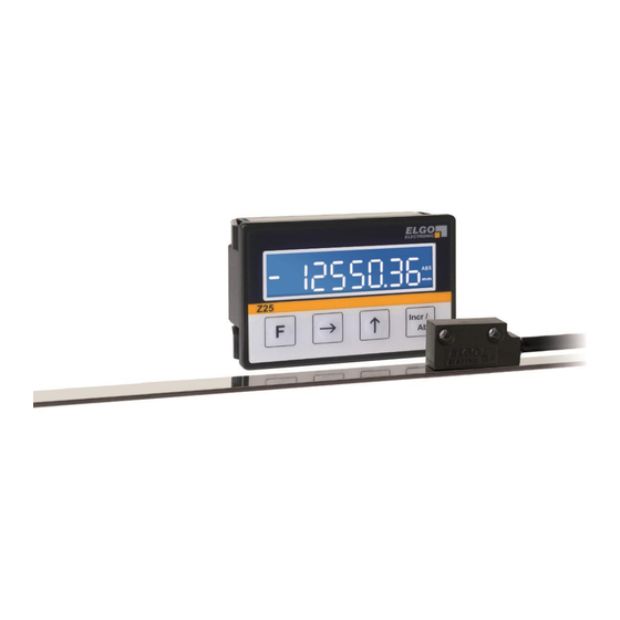
Single Axis Position Indicator (24 VDC)
Position indicator with signal input for 1 axis
Suitable for conventional rotary and linear encoder and
for incremental and absolute ELGO measuring systems
Adjustable reference value, tool offset and saw blade width
LCD display with 7 digits, sign and measurement unit
2 programmable digital control inputs
Power down memory
Advertisement
Table of Contents

Related Manuals for ELGO Electronic Z25

Summary of Contents for ELGO Electronic Z25
- Page 1 799000592 / Rev. 4 / 2017-05-08 Translation of the original operating manual Operating Manual SERIES Z25-000 Single Axis Position Indicator (24 VDC) Position indicator with signal input for 1 axis Suitable for conventional rotary and linear encoder and for incremental and absolute ELGO measuring systems ...
-
Page 2: D-78239 Rielasingen-Worblingen
+49 (0) 7731 9339 – 0 +49 (0) 7731 2 13 11 info@elgo.de Document- No. 799000592 Document- Name Z25-000-MA-E_17-19 Document- Revision Rev. 4 Issue Date 2017-05-08 Copyright © 2017, ELGO Electronic GmbH & Co. KG - 2 -... -
Page 3: Table Of Contents
Product Features ..................7 General information ......................7 Product Features ....................... 7 Technical Data ................... 8 Identification ........................8 Dimensions Z25 ....................... 8 Technical Data ......................... 8 Installation and First Start-Up ..............9 Operating Area ........................ 9 Design and Functions ................10 External Inputs ........................ -
Page 4: General, Safety, Transport And Storage
General, Safety, Transport and Storage 2 General, Safety, Transport and Storage Information Operating Manual This manual contains important information regarding the handling of the device. For your own safety and operational safety, please ob- serve all safety warnings and instructions. Precondition for safe operation is the compliance with the specified safety and handling instruc- tions. -
Page 5: Statement Of Warranties
General, Safety, Transport and Storage Statement of Warranties The producer guarantees the functional capability of the process engineering and the selected parameters. Demounting and Disposal Unless acceptance and disposal of returned goods are agreed upon, demount the device considering the safety instructions of this manual and dispose it with respect to the environment. -
Page 6: Conventional Use
The ELGO-device is only conceived for the conventional use described in this manual. The ELGO Z25-000 position indicator only serves to visualize positions, pulses or other specified units. CAUTION! Danger through non-conventional use! Non-intended use and non-observance of this operating manual can lead to dangerous situations. -
Page 7: Product Features
Product Features 3 Product Features General information The compact Z25 position indicator has a 10 mm high LCD display which allows a comfortable and accurate reading actual positions. Commands like Reset or Preset to an arbitrary reference value can be done either via the dustproof front keypad or external signals to 0 or to an arbitrary reference value. -
Page 8: Technical Data
(=order reference 11) with the corresponding part number. Furthermore, the type label contains a unique, traceable device number. When corresponding with ELGO please always indicate this data. Dimensions Z25 Figure 1: Z25 dimensions Technical Data Display unit Z25-000 Power supply voltage... -
Page 9: Installation And First Start-Up
Installation and First Start-Up 5 Installation and First Start-Up CAUTION Please read the operating manual carefully before using the device! Strictly observe the Installation instructions! In case of damage caused by failure to observe this operating manual, the warranty expires. ELGO is not liable for any secondary damage and for damage to persons, property or assets. -
Page 10: Design And Functions
Design and Functions 6 Design and Functions The Z25 unit has 4 front-panel keys. The figure below shows the respective basic functions: Function key Menu navigation for parameter level Incremental / Absolute switchover Figure 2: Key assignment of Z25 The functions and key combinations of the keys are described in next section ( 6.3). -
Page 11: Key Functions
Design and Functions Key Functions The operation of the device is divided into 2 levels: Parameter level: For configuration of the main operating parameters ( 7). User level: Allows access to the basic functions of the unit (depends on software version). ... -
Page 12: Parameter Level
Parameter Level 7 Parameter Level This section describes the available parameters and their settings. A parameter list for a quick overview of all available parameters can be found in the next chapter ( 8). Specific customer settings can be added there. P01: Counting direction Up / down switchover (0: forwards, 1: backwards) P02: Display mode (measurement unit) - Page 13 Parameter Level P10: Tool offset A tool offset can be defined here. Range: 000000.1 … 999999.9 P11: Saw blade The saw blade thickness can be entered here. Range: 0000.1 … 9999.9 P16: Default Initialization Parameters are reset to default values. (0: not init., 1: default init.) Enter „1“...
-
Page 14: Parameter List
Parameter List 8 Parameter List Table 1: Parameter List Par. No. Function Default setting Description Customer settings Counting direction upwards Measurement unit (display) Decimal place 1 decimal place Reserved Keyboard lock disabled Edge evaluation 1 edge triggering Encoder system selection Incremental Multiplication factor 01.00000... -
Page 15: Connections
Connections 9 Connections Table 2: Assignment of the RIA terminal Connector S1: 8 pin RIA terminal Function 0 V / GND (encoder supply output) +24 VDC (encoder supply output) HTL channel A HTL channel B Control input 1 (24 V-PNP) Control input 2 (24 V-PNP) 0 V / GND (power supply input) +24 VDC (power supply input) -
Page 16: Disturbances, Maintenance, Cleaning
External perturbations can be avoided thorough suitable cable routing. The screen of the signal output cable should only be connected to the following Z25 circuit on one side. The figure shows how the shield is connected to the Z25 position indicator to avoid interference. -
Page 17: Re-Start After Fault Clearance
Disturbances, Maintenance, Cleaning 10.3 Re-start after Fault Clearance After the fault clearance: Reset the emergency stop mechanism if necessary Reset the error report at the super-ordinate system if necessary. Ensure that there are no persons in the danger area. Follow the instructions from chapter 5. WARNING! Danger of injury through non-conventional fault clearance! Non-conventional fault clearance can lead to severe injuries and damage of property. -
Page 18: Type Designation
When ordering, please use the here described ordering code (Type Designation). Options that are not required are filled in with „-„. 11.1 Accessories Table 5: Accessories Order Designation Description NG24.0 External 24 VDC power pack (primary 115/230 VAC) as power supply for Z25 - 18 -... -
Page 19: Index
Product features ..........7 Demounting ............5 Product Features ..........7 Device number ..........8 Protection against contact ........9 Dimensions Z25 ..........8 Protective equipment ......... 5 Disposal............5 Reference value ..........11 Disturbances ........... 16 Regular modes ..........11 edge evaluation .......... -
Page 20: Carl-Benz-Str
Document- No.: 799000592 / Rev. 4 ELGO Electronic GmbH & Co. KG Measuring | Positioning | Control Document- Name: Z25-000-MA-E_17-19 Carl - Benz - Str. 1, D-78239 Rielasingen Subject to change - © 2017 Fon:+49 (0) 7731 9339-0, Fax:+49 (0) 7731 28803 Internet: www.elgo.de, Mail: info@elgo.de...
Need help?
Do you have a question about the Z25 and is the answer not in the manual?
Questions and answers