Table of Contents
Advertisement
Quick Links
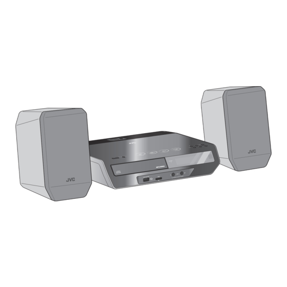
SERVICE MANUAL
MICRO COMPONENT SYSTEM
6 S ERVICE MANUAL
MB617
2007
UX-EP100A, UX-EP100US,
UX-EP100UB, UX-EP100UW,
UX-EP100UP, UX-EP100UT
COPYRIGHT © 2007 Victor Company of Japan, Limited
Lead free solder used in the board (material : Sn-Ag-Cu, melting point : 219 Centigrade)
Lead free solder used in the board (material : Sn-Cu, melting point : 230 Centigrade)
1
PRECAUTION. . . . . . . . . . . . . . . . . . . . . . . . . . . . . . . . . . . . . . . . . . . . . . . . . . . . . . . . . . . . . . . . . . . . . . . . . 1-3
2
SPECIFIC SERVICE INSTRUCTIONS . . . . . . . . . . . . . . . . . . . . . . . . . . . . . . . . . . . . . . . . . . . . . . . . . . . . . . 1-6
3
DISASSEMBLY . . . . . . . . . . . . . . . . . . . . . . . . . . . . . . . . . . . . . . . . . . . . . . . . . . . . . . . . . . . . . . . . . . . . . . . 1-7
4
ADJUSTMENT . . . . . . . . . . . . . . . . . . . . . . . . . . . . . . . . . . . . . . . . . . . . . . . . . . . . . . . . . . . . . . . . . . . . . . . 1-18
5
TROUBLESHOOTING . . . . . . . . . . . . . . . . . . . . . . . . . . . . . . . . . . . . . . . . . . . . . . . . . . . . . . . . . . . . . . . . . 1-18
SP-UXEP100
TABLE OF CONTENTS
COPYRIGHT © 2007 Victor Company of Japan, Limited
CA-UXEP100
SP-UXEP100
No.MB617
2007/7
Advertisement
Chapters
Table of Contents

Related Manuals for JVC UX-EP100A


Summary of Contents for JVC UX-EP100A
-
Page 1: Table Of Contents
SERVICE MANUAL MICRO COMPONENT SYSTEM MB617 2007 6 S ERVICE MANUAL UX-EP100A, UX-EP100US, UX-EP100UB, UX-EP100UW, UX-EP100UP, UX-EP100UT SP-UXEP100 CA-UXEP100 SP-UXEP100 COPYRIGHT © 2007 Victor Company of Japan, Limited Lead free solder used in the board (material : Sn-Ag-Cu, melting point : 219 Centigrade) - Page 2 SPECIFICATION 20 W (10 W + 10 W) at 6 Ω (10% THD) Amplifier section OUTPUT POWER 6 Ω - 16 Ω Speakers/Impedance Audio input LINE IN 500 mV/47 kΩ (at “LINE IN LVL1”) 250 mV/47 kΩ (at “LINE IN LVL2”) 125 mV/47 kΩ...
-
Page 3: Precaution
SECTION 1 PRECAUTION Safety Precautions (1) This design of this product contains special hardware and voltmeter. many circuits and components specially for safety purpos- Move the resistor connection to each exposed metal es. For continued protection, no changes should be made part, particularly any exposed metal part having a return to the original design unless authorized in writing by the path to the chassis, and measure the AC voltage across... - Page 4 Preventing static electricity Electrostatic discharge (ESD), which occurs when static electricity stored in the body, fabric, etc. is discharged, can destroy the laser diode in the traverse unit (optical pickup). Take care to prevent this when performing repairs. 1.5.1 Grounding to prevent damage by static electricity Static electricity in the work area can destroy the optical pickup (laser diode) in devices such as laser products.
- Page 5 Important for laser products 1.CLASS 1 LASER PRODUCT 5.CAUTION : If safety switches malfunction, the laser is able to function. 2.CAUTION : (For U.S.A.) Visible and/or invisible class II laser radiation 6.CAUTION : Use of controls, adjustments or performance of when open.
-
Page 6: Specific Service Instructions
SECTION 2 SPECIFIC SERVICE INSTRUCTIONS This service manual does not describe SPECIFIC SERVICE INSTRUCTIONS. 1-6 (No.MB617) -
Page 7: Disassembly
SECTION 3 DISASSEMBLY Main body 3.1.1 Removing the TOP PANEL assembly (See Fig.1, 2) (1) Remove the three screws A attaching the TOP PANEL as- sembly. (See Fig.1) (2) Lift up the TOP PANEL assembly, disconnect the card wire from MAIN BOARD assembly connected to connector CN431 of the TACT &... -
Page 8: Remove The Four Screws B Attaching The Bottom Case See Fig
3.1.2 Removing the BOTTOM CASE (See Fig.3 to 5) (1) Remove the four screws B attaching the BOTTOM CASE. (See Fig.3) (2) Remove the two screws C attaching the SPEAKER TER- MINAL. (See Fig.4) (3) Disconnect the POWER CORD from connector P901 of the POWER BOARD assembly. - Page 9 3.1.3 Removing the FRONT PANEL assembly (See Fig.6 to 8) (1) Remove the FITTING. (2) Disconnect the card wire from FRONT PANEL assembly CN701 connected to connector CN701 of the MAIN BOARD as- sembly. (See Fig.6) (3) Disengage the two hooks a and three hooks b engaged both side of the FRONT PANEL assembly.
- Page 10 3.1.4 Removing the CD MECHANISM assembly (See Fig.9, 10) (1) Disconnect the connector wire from CD MECHANISM as- sembly connected to connector CN104 CN708 of the MAIN BOARD assembly. (See Fig.9) (2) Remove the one screw D attaching the CD MECHANISM assembly.
-
Page 11: See Fig.
3.1.5 Removing the POWER BOARD assembly (See Fig.11) (1) Disconnect the connector wire from POWER BOARD as- sembly connected to connector CN373 of the MAIN BOARD assembly. (2) Remove the three screws E attaching the BRACKET. CN373 Fig.11 3.1.6 Removing the VFD BOARD assembly (See Fig.12) (1) Remove the two screws F attaching the VFD BOARD as- sembly. -
Page 12: No.mb617)1
CD mechanism assembly • Remove the CD mechanism assembly from main body. 3.2.1 Removing the CD cover (See Fig.1) (1) Remove the two screws A attaching the CD cover from bot- tom side of CD mechanism assembly. Boss a Fixing part b (2) Lift up the CD cover from disengage boss a of the CD mechanism assembly. - Page 13 3.2.3 Removing the traverse mechanism assembly (See Fig.4) (1) Remove the four screws C attaching the traverse mecha- CD mechanism assembly nism assembly from bottom side of CD mechanism assem- bly. CD servo board Card wire (2) Disconnect the card wire from connector CN602 of the CD servo board and then take out the traverse mechanism as-...
-
Page 14: No.mb617)1
3.2.4 Removing the CD servo board (See Fig.5 and 6) • Remove the traverse mechanism assembly. Solder part e Yellow wire (1) Remove the two screws D attaching the CD servo board from bottom side of traverse mechanism assembly. (See Fig.5) (2) Remove the solder from solder part e of the CD servo White wire... -
Page 15: See Fig.
3.2.5 Removing the pickup (See Fig.7 to 9) • Remove the traverse mechanism assembly. (1) Remove the one screw E attaching the plate from upper Feed gear Shaft LEAD spring side of traverse mechanism assembly. (See Fig.7) (2) Remove the plate from fixing part k then take out the plate. (See Fig.7) Part m (3) Remove the two screws F attaching the LEAD spring and... - Page 16 3.2.7 Removing the feed motor (See Fig.11 to 13) • Remove the traverse mechanism. Yellow wire (1) Remove the yellow wire from solder part q of the CD servo board from upper side of traverse mechanism. (See Fig.11) (2) Remove the white wire from solder part r of the CD servo White wire board.
- Page 17 3.2.8 Removing the switch board (See Fig.14) (1) Disconnect the card wire from of the switch board Hook v Switch board Wire from bottom side of CD mechanism assembly. (2) Remove the wire from solder part u of the switch board. Solder (3) Remove the one screw H attaching the switch board to CD part u...
-
Page 18: Adjustment
SECTION 4 ADJUSTMENT TEST MODE BUTTON INDICATION FUNCTION [POWER] COLD COLD START (Initialization of set) [SET] [REPEAT] [POWER] V_E_RDS Version indication [SET] [FM MODE/PLAY MODE] [POWER] (FL ALL DISPLAY) FL all display [SET] [S.TURBO] [POWER] VOL MAX Volume level to max by compulsion. [SET] [FADE MUTING] V_E_RDS... - Page 19 (No.MB617)1-19...
- Page 20 Victor company of Japan, Limited Audio/Video Systems category 10-1,1chome,Ohwatari-machi,Maebashi-city,Gumma-ken, 371-8543,Japan (No.MB617) Printed in Japan...
- Page 21 SCHEMATIC DIAGRAMS MICRO COMPONENT SYSTEM UX-EP100A,UX-EP100US,UX-EP100UB UX-EP100UW,UX-EP100UP,UX-EP100UT CD-ROM No.SML200707 SP-UXEP100 CA-UXEP100 SP-UXEP100 Lead free solder used in the board (material : Sn-Ag-Cu, melting point : 219 Centigrade) Lead free solder used in the board (material : Sn-Cu, melting point : 230 Centigrade)
- Page 22 In regard with component parts appearing on the silk-screen printed side (parts side) of the PWB diagrams, the parts that are printed over with black such as the resistor ( ), diode ( ) and ICP ( ) or identified by the " " mark nearby are critical for safety.
-
Page 23: Block Diagram
Block diagram IPOD System control & Audio Amp section IC970 IPOD AMP. HPDET section HPMUTE HEAD CN970 IC801 PHONE LOUT, ROUT W9700 Q8102,Q8103,Q8301 IPODLIN IPODLOUT HP AMP./MUTE IPODRIN IPODROUT DG-SENE, IPODTX, IPODRX LOPOUT LINP L+/- IPOD ROPOUT Q3601,Q3602 RINP IC501 R+/- IC375 POWER AMP. - Page 24 Standard schematic diagrams DC regulator & VFD board section D901 KBJ4J CN901 QJK005-070502-E 0.0022/2000 T901 QQS0397-001 FC901 FC902 QNG0019-001Z QNG0019-001Z L954 C909 R903 D954 QQL31AK-220Z L901 GDMBR10100 C957 C958 1000/16 220/16 C908 D903 C907 P901 330P/2000 SF27-B351C C961 1000/16 D902 SF27-B351C QGA7901C1-02 QQR1786-001...
- Page 25 CD system control section CN201 CN203 QJK043-050600-E QGF1040F1-23 TRV+ TRV- IC721 LB1641 C653 C654 0.047 C651 C652 R642 R641 0.047 0.047 C7203 47/16 C649 0.01 C7202 C650 47/16 CN721 IC601 QGF1040F1-05 LA6242H-X D605 R644 R645 MA152WA-X R647 R648 3.3K C646 R651 R650 CN102...
- Page 26 System control & Touch screen section CN706 QJK043-060601-E CN103 QNZ0926-001 IC403 NJM4565M-WE R7102 W101 WJZ0227-002A-E C116 C114 Q4401 RT1N140C-X C115 R4405 R4404 C4402 R4402 C4401 C111 C4403 R4401 BACKUPMUTE R7092 C112 100K R4403 Q4402 RT3WLMM/EF/-X D103 R7042 2.2K TUCE UDZW6.2B-X R4103 2.2K R7041...
- Page 27 QGB2510J1-04 Q3706 4.7K 2SC3928A/QR/-X Q4604 Q4606 KTC812T-X RT1P141C-X Q3702 RT1P441C-X R3703 Q3708 Q3709 QGB2510K2-04 RT1P430C-X 0.001 CN802 C3799 RT1N141C-X Q3701 2SC3576-JVC-T IC372 IC375 MM1565AF-X RT9164A-PG-X C3717 C8307 MM1565AF-X C3720 1.5/6.3 C8305 MTZJ30C-T2 R3713 D3701 IC373 C8106 MM1594AF-X C3721 D3706 470P C8306 1.5/6.3...
- Page 28 iPod baby board section Loader section GVA10154-A1 IC970 NJM4580D C9704 150P R9704 K9701 C9701 R9702 QQL231K-4R7Y 10/50 4.2V 4.2V R9703 C9702 10/50 4.2V R9705 R9700 K9700 C9705 150P QSW1074-001 QQL231K-4R7Y C9804 150P C9700 0.047 R9804 C9801 NJM4580D 10/50 IC970 4.2V R9802 K9702 C9802...
-
Page 29: Printed Circuit Boards
Printed circuit boards CN431 Main board Lead free solder used in the board (material : Sn-Ag-Cu, melting point : 219 Centigrade) R4006 Lead free solder used in the board (material : Sn-Cu, melting point : 230 Centigrade) forward side R4007 C4018 C4006 (Tact/Touch/LED board) - Page 30 Main board Lead free solder used in the board (material : Sn-Ag-Cu, melting point : 219 Centigrade) Lead free solder used in the board (material : Sn-Cu, melting point : 230 Centigrade) reverse side (Tact/Touch/LED board) (VFD board) R4015 C4012 Q4012 DI221 IC241...
- Page 31 CD board Lead free solder used in the board (material : Sn-Ag-Cu, melting point : 219 Centigrade) Lead free solder used in the board (material : Sn-Cu, melting point : 230 Centigrade) forward side reverse side C611 C615 C609 R619 L101 L101 TP205...
- Page 32 Victor Company of Japan, Limited Audio/Video Systems Category 10-1,1chome,Ohwatari-machi,Maebashi-city,371-8543,Japan Printed in Japan (No.MB617SCH)
-
Page 33: Parts List
PARTS LIST UX-EP100A,UX-EP100US,UX-EP100UB UX-EP100UW,UX-EP100UP,UX-EP100UT * All printed circuit boards and its assemblies are not available as service parts. - Contents - 3- 2 Exploded view of general assembly and parts list (Block No.M1) 3- 5 CD mechanism assembly and parts list (Block No.MB) 3- 7 CD loading base assembly and parts list (Block No.MD) -
Page 34: Exploded View Of General Assembly And Parts List (Block No.m1)
Exploded view of general assembly and parts list Block No. VFD board Headphone bo Power board... - Page 35 TACT/TOUCH/LED board Headphone board Main board UP only UT only UT,UP ver The parts without symbol number are not service.
- Page 36 General Assembly Block No. [M][1][M][M] Symbol No. Part No. Part Name Description Local GN10110-003A FRONT PANEL GN10110-002A FRONT PANEL US,UB,UW,UP,UT GN30207-003A WINDOW SCREEN QYSDSF2608ZA TAP SCREW M2.6 x 8mm(x3) GN10113-003A CHASSIS BASE GN20211-002A BRACKET GN20216-004A PROTECT SHEET QYSBST3006ZA TAP SCREW M3 x 6mm(x3) QYSBSGG3006EA TAP SCREW...
-
Page 37: Cd Mechanism Assembly And Parts List (Block No.mb)
CD mechanism assembly and parts list Block No. Grease JVG-31N GTU-MS1-2M JVS-1003 FL-7750E E-460 3.5mm 0.1mm 12.0mm 0.1mm < Back side > CD servo board The parts without symbol number are not service. - Page 38 CD mechanism Block No. [M][B][M][M] Symbol No. Part No. Part Name Description Local QAL0844-001 PICK UP LV22529-002A RACK ARM VKZ4777-012 MINI SCREW (x2) LV37574-001A RACK ARM SPRING QYSPSGT1425MA TAP SCREW M1.4 x 2.5mm LV10855-004A TM CHASISS LV43648-001A TURN TABLE LV31744-001A P.S.SPRING QAR0302-001...
-
Page 39: Cd Loading Base Assembly And Parts List (Block No.md)
CD loading base assembly and parts list Block No. GMU-MS1-2M Grease JVS-1003 CFD-4007ZY2 < Back side > < Top view > Backside CD loading switch board The parts without symbol number are not service. - Page 40 CD loading base Block No. [M][D][M][M] Symbol No. Part No. Part Name Description Local LV11065-010A LOADER SUB ASSY E407140-001SS C.D ROLLER E407149-001SS RUBBER TUBE LV10979-003A TRAY LV35499-003A SHAFT GUIDE LV44022-001A SHAFT QYSSSF2008ZA TAP SCREW M2 x 8mm QYSDSF2008ZA TAP SCREW M2 x 8mm(x2) LV41741-004A SPECIAL SCREW...
-
Page 41: Electrical Parts List (Block No.01~04)
TRANSISTOR C2204 NCB31CK-104X C CAPACITOR 0.1uF 16V K Q3602 2SC5938A/B/-X TRANSISTOR C2205 NCB31HK-223X C CAPACITOR 0.022uF 50V K Q3701 2SC3576-JVC-T TRANSISTOR C2207 NCF31AZ-105X C CAPACITOR 1uF 10V Z Q3702 RT1P441C-X DIGI TRANSISTOR C2208 NCF31AZ-105X C CAPACITOR 1uF 10V Z Q3710... - Page 42 Symbol No. Part No. Part Name Description Local Symbol No. Part No. Part Name Description Local C3708 QEKJ1CM-107Z E CAPACITOR 100uF 16V M C5115 QEKC1HM-106Z E CAPACITOR 10uF 50V M C3709 NCB31HK-471X C CAPACITOR 470pF 50V K C5116 QEKC1HM-106Z E CAPACITOR 10uF 50V M...
- Page 43 Symbol No. Part No. Part Name Description Local Symbol No. Part No. Part Name Description Local C9702 QERF1CM-106Z E CAPACITOR 10uF 16V M R3713 NRSA63F-121X MG RESISTOR 120Ω 1/16W F C9704 NDC31HJ-151X C CAPACITOR 150pF 50V J R3714 NRSA63J-271X MG RESISTOR 270Ω...
- Page 44 Symbol No. Part No. Part Name Description Local Symbol No. Part No. Part Name Description Local R4609 NRSA63J-473X MG RESISTOR 47kΩ 1/16W J R7041 NRSA63J-222X MG RESISTOR 2.2kΩ 1/16W J R4610 NRSA63J-332X MG RESISTOR 3.3kΩ 1/16W J R7042 NRSA63J-222X MG RESISTOR 2.2kΩ...
-
Page 45: Power Board
Symbol No. Part No. Part Name Description Local Symbol No. Part No. Part Name Description Local R9703 NRSA63J-223X MG RESISTOR 22kΩ 1/16W J S2504 QSW1120-001Z PUSH SW R9704 NRSA63J-223X MG RESISTOR 22kΩ 1/16W J S2505 NSW0306-001X TACT SWITCH R9705 NRSA63J-223X MG RESISTOR... - Page 46 Symbol No. Part No. Part Name Description Local Symbol No. Part No. Part Name Description Local R957 NRSA63J-392X MG RESISTOR 3.9kΩ 1/16W J C624 QERF1AM-227Z E CAPACITOR 220uF 10V M R958 NRSA63J-102X MG RESISTOR 1kΩ 1/16W J C625 QEKJ0JM-476Z E CAPACITOR 47uF 6.3V M...
- Page 47 Symbol No. Part No. Part Name Description Local R643 NRSA63J-562X MG RESISTOR 5.6kΩ 1/16W J R644 NRSA63J-153X MG RESISTOR 15kΩ 1/16W J R645 NRSA63J-273X MG RESISTOR 27kΩ 1/16W J R646 NRSA63J-562X MG RESISTOR 5.6kΩ 1/16W J R647 NRSA63J-103X MG RESISTOR 10kΩ...
-
Page 48: Packing Materials And Accessories Parts List (Block No.m3)
Packing materials and accessories parts list Block No. No additional / supplemental order of WARRANTY CARDs are available A1,A2,A3,A4,A5,A7,A8,A9, A10,A11,A13,A14,A15,A16 UB only The parts without symbol number are not service. 3-16... - Page 49 Packing and Accessories Block No. [M][3][M][M] Symbol No. Part No. Part Name Description Local GNT0076-024A INST BOOK GNT0076-017A INST BOOK US,UB,UW,UT GNT0076-022A INST BOOK GNT0076-018A INST BOOK CHI(PEKIN) US,UB GNT0076-019A INST BOOK GNT0076-023A INST BOOK CHI(TAIWAN) RM-SUXEP100J REMCON UNIT RM-SUXEP100U REMCON UNIT US,UB,UW,UP,UT...