Chapters
Table of Contents

Subscribe to Our Youtube Channel
Related Manuals for BK Precision 4040A


Summary of Contents for BK Precision 4040A
- Page 1 INSTRUCTION MANUAL Model 4040A MANUAL DE INSTRUCCIÓN MODELO 4040A 20 MHz SWEEP/FUNCTION GENERATOR with FREQUENCY COUNTER 20 MHz GENERADOR DE BARRIDO/FUNCIONES CON CONTADOR DE FRECUENCIA...
- Page 2 Normal use of test equipment exposes you to a certain amount of danger from electrical shock because testing must sometimes be performed where exposed voltage is present. An electrical shock causing 10 milliamps of current to pass through the heart will stop most human heartbeats.
- Page 3 Instruction Manual for Model 4040A 20 MHz SWEEP/FUNCTION GENERATOR with FREQUENCY COUNTER 22820 Savi Ranch Parkway • Yorba Linda, CA 92887...
-
Page 4: Table Of Contents
TEST INSTRUMENT SAFETY ...inside front cover INTRODUCTION ... 5 SPECIFICATIONS ... 6 CONTROLS AND INDICATORS ... 8 OPERATING INSTRUCTIONS ... 11 Frequency and Waveform Selection ..11 Duty Cycle Control ... 13 Burst Operation ... 14 AM Operation ... 15 FM Operation . -
Page 5: Introduction
INTRODUCTION The B&K Precision Model 4040A Sweep/Function Generator is a versatile signal source which combines several functions into one unit - waveform generation, pulse generation (through variable symmetry), and frequency sweep. Additionally, the instrument provides the added convenience of a built-in frequency counter. -
Page 6: Specifications
FREQUENCY CHARACTERISTICS Waveforms: Sine, Square, Triangle, ± Pulse, ± Ramp Range: 0.2Hz to 20MHZ in 8 ranges Resolution: Tuning Range: Coarse: 10:1, Fine: ± 5% of Coarse Setting Variable Duty Cycle 15:85:15 Continuously Variable Operating Modes Normal, Sweep, VCG, AM, FM, Burst Frequency Stability: The output will change less than 0.09% over 15 minutes after 1 hour warmup. -
Page 7: Specifications
SPECIFICATIONS SWEEP OPERATION Mode: LIN / LOG Width: 100:1, Continuously variable Rate: 20mS to 2 sec, continuously variable Sweep Output: 0 to 2V Start/Stop Frequencies: Adjustable AM MODULATION CHARACTERISTICS Source: Internal, External Modulation Ratio: 0 To 100% INT. Modulation: 1kHz EXT. -
Page 8: Controls And Indicators
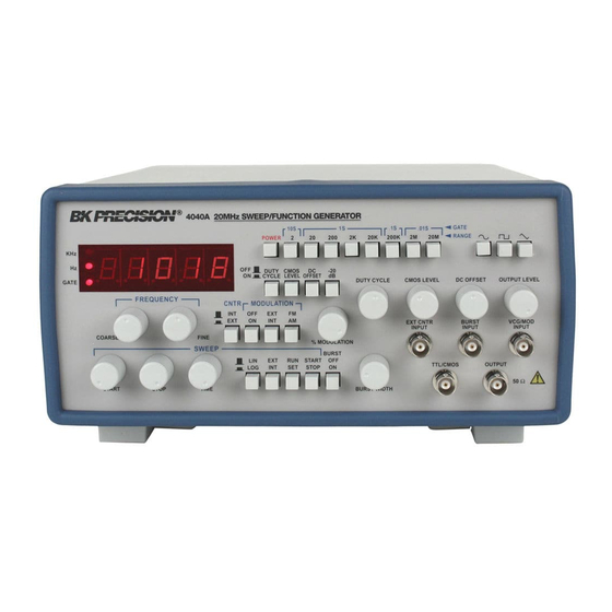
CONTROLS AND INDICATORS 10. OUTPUT LEVEL Control. Controls the amplitude of the signal at the OUTPUT jack. Output level can be decreased by approximately 20dB with this control. 11. DC OFFSET Control. Activated by the DC OFFSET Switch (4). Clockwise rotation from center changes counterclockwise rotation from center changes the DC offset in a negative direction. - Page 9 18. % MODULATION Control. Adjusts the percentage of AM or FM modulation. Figure 1. Model 4040A Front Panel. 19 BURST OFF/ON Switch. Selects external or internal burst gate. Continuous output is obtained with switch in the OFF position and no external...
- Page 10 CONTROLS AND INDICATORS 20. .START/STOP Switch. Enables adjustment of the starting and stopping sweep frequencies. The actual adjustment is performed by the SWEEP START and SWEEP STOP controls (29 and 27). START/STOP selection is enabled only when the SET/RUN switch (21) is set to SET. 21.
-
Page 11: Operating Instructions
The B&K Precision Model 4040A Sweep/Function Generator is a versatile instrument, capable of producing a variety of output waveforms over a broad range of frequencies. To gain a working familiarity with the unit, it is recommended that it be connected initially to an oscilloscope, so that the effects of the various controls on the output waveforms can be observed. - Page 12 OPERATING INSTRUCTIONS 6. Adjust the amplitude of the output as desired using the OUTPUT LEVEL control (10). Rotation of this control varies the amplitude from maximum to 20dB below maximum. An additional attenuation of -20dB is available by pushing in the -20dB switch (5). The attenuation factors can be combined for a total of -40dB.
-
Page 13: Duty Cycle Control
4. When the 2 Hz range is selected, the gate time is 10 seconds and the display is updated once every 10 seconds. The result of a frequency change will not be displayed until 10 seconds later. Adjust the frequency in progressively smaller steps, waiting for the display to update until the desired frequency is obtained. -
Page 14: Burst Operation
OPERATING INSTRUCTIONS 3. Varying the duty cycle setting results in a slight change in frequency. Adjust the COARSE and FINE frequency controls as required. BURST OPERATION In gated burst mode of operation, the generator output is switched on and off (gated), either by an internally generated signal or by an externally applied signal. -
Page 15: Am Operation
The formula is: External viewing eliminates OPERATING INSTRUCTIONS The output of Model 4040A can be amplitude-modulated, 1. Set the carrier frequency using the main FREQUENCY controls and RANGE switches. 2. Engage the MODULATION ON and AM MODULATION switches. -
Page 16: Fm Operation
OPERATING INSTRUCTIONS Figure 6. Examples of AM modulation 3. Place the EXT MODULATION switch in the released position. 4. Connect a suitable modulating signal to the VCG/MOD INPUT jack on the front panel. 5. Adjust the modulation level as described previously. FM OPERATION The output of the Model 4040 can be frequency-modulated, either by the internal 1 kHz internal signal or by an external signal applied to the front... -
Page 17: Ttl/Cmos Output
CMOS LEVEL control (8). VOLTAGE CONTROLLED FREQUENCY OPERATION The Model 4040A can be operated as a voltage-controlled generator by using an external control voltage applied to the VCG/MOD INPUT jack (12). The externally applied voltage... -
Page 18: Sweep Operation
OPERATING INSTRUCTIONS SWEEP OPERATION 1. Select LINEAR sweep by leaving the SWEEP LIN/LOG switch (23) in the released position or select LOG sweep by engaging the SWEEP LIN/LOG switch. 2. Rotate COARSE FREQUENCY Control to minimum (CCW). 3. Engage the RUN/SET switch to adjust the start and stop sweep frequencies. -
Page 19: Output Protection Considerations
OUTPUT PROTECTION CONSIDERATIONS Use care when connecting the function generator output to a signal injection point. Excessive voltage at the point of signal injection of the function generator can cause internal damage. Under normal operation, the generator output should never be connected to an external voltage other than low dc values that can be matched with the DC OFFSET control. -
Page 20: Maintenance
WARNING The following instructions are for use by qualified service personnel only. To avoid electrical shock, do not perform servicing other than contained in the operating instructions unless you are qualified to do so. Remember that ac line voltage is present on line voltage input circuits any time the instrument is plugged into an ac outlet, even if turned off. -
Page 21: Customer Support
B+K Precision offers courteous, professional technical support before and after the sale of their test instruments. The following services are typical of those available from our toll-free telephone number: Technical advice on the use of your instrument. Technical advice on special applications of your instrument. Technical advice on selecting the best instrument for a given task. -
Page 22: Warranty Service Instructions
Service Information Warranty Service: Please return the product in the original packaging with proof of purchase to the address below. Clearly state in writing the performance problem and return any leads, probes, connectors and accessories that you are using with the device. Non-Warranty Service: Return the product in the original packaging to the address below. -
Page 23: Limited Two-Year Warranty
Limited Two-Year Warranty B&K Precision Corp. warrants to the original purchaser that its products and the component parts thereof, will be free from defects in workmanship and materials for a period of two years from date of purchase. B&K Precision Corp. will, without charge, repair or replace, at its option, defective product or component parts. Returned product must be accompanied by proof of the purchase date in the form of a sales receipt. - Page 24 6. Some equipment with a two-wire ac power cord, including some with polarized power plugs, is the “hot chassis” type. This includes most recent television receivers and audio equipment. A plastic or wooden cabinet insulates the chassis to protect the customer.
-
Page 25: Spanish Manual
SEGURIDAD DEL INSTRUMENTO DE PRUEBA El Uso normal de equipo de prueba lo expone a cierto riesgo de choque eléctrico cuando efectúa pruebas donde hay alto voltaje descubierto. Un choque eléctrico que cause una corriente de 10 mili amperes a través del corazón pararía la mayoría de los corazones humanos. Un voltaje tan bajo como de 35 volts DC o AC rms podría considerarse de peligro porque puede producir una corriente letal bajo ciertas condiciones. - Page 26 MANUAL DE USUARIO MODELO 4040A 20MHz GENERADOR DE BARRIDO/FUNCIONES CON CONTADOR DE FRECUENCIA 22820 Savi Ranch Parkway • Yorba Linda, CA 92887...
- Page 27 SEGURIDAD DEL INSTRUMENTO DE PRUEBA INTRODUCION ... 28 ESPECIFICACIONES ... 29 CONTROLES E INDICADORES ... 31 INSTRUCCIONES DE OPERACIÓN ... 34 Selección de frecuencia y forma de onda ... 34 Consideraciones ... 35 Control de ciclo de servicio... 36 Operación de ráfaga... 37 Operación AM...
-
Page 28: Seguridad Del Instrumento De Prueba Introducion
El B & K Precision modelo 4040A Barrido/Función generador es una versátil fuente de señales que combina varias funciones en una unidad- generador de formas de onda, generador de pulsos (a través de simetría variable), y barrido de frecuencia. Adicionalmente, el instrumento provee la conveniencia adicional de incluir un contador de frecuencia. -
Page 29: Especificaciones
CARACTERÍSTICAS DE FRECUENCIA Formas de onda : seno,cuadrada,triangular, ±pulso,±rampa Rango : 0.2Hz a 20MHz en 8 rangos Resolución : 5 dígitos Rango de sintonía : grueso 10:1, Fino ±5% de posición gruesa Ciclo de servicio variable : 15:85:15 continuamente variable Modos de operación : normal,barrido,VCG, AM, FM, ráfaga... - Page 30 ESPECIFICACIONES OPERACIÓN DE BARRIDO Modo : LIN/LOG Ancho : 00:1,continuamente variable Velocida : 20ms a 2s continuamente variable Salida de barrido : 0 a 2V Frecuencia de inicio/paro : Ajustable CARACTERISTICAS DE MODULACION AM Fuente : Interna, externa Desviación : 0 a 5% Modulación INT : 1KHz Modulación EXT...
-
Page 31: Controles E Indicadores
PANEL DELANTERO (Vea la Fig. 1) 1. INTERRUPTOR DE ENCENDIDO (POWER). Enciende y apaga el instrumento. 2. Switch DUTY CYCLE. Su activación habilita la operación del control DUTY CYCLE(7). 3. Switch CMOS LEVEL. Accionado, cambia la señal TTL a señal CMOS en el jack TTL/CMOS jack, y permite la operación del Control CMOS LEVEL (8) 4. - Page 32 CONTROLES E INDICADORES 17. Control BURST WIDTH. Ajusta el ciclo de servicio del interruptor interno de ráfaga 18. % MODULATION. Ajusta el porcentaje de modulación AM o FM 19. Switch BURST OFF/ON. Selecciona interruptor de ráfaga externa o interna. En la posición OFF la salida es continua y no se aplica la señal de ráfaga interna 20.
- Page 33 Figura 1. Panel frontal del modelo 4040A...
-
Page 34: Instrucciones De Operación
INSTRUCCIONES DE OPERACIÓN El Generador de funciones B&K Precison Modelo 4040A es un Figura 2. Formas de onda de salida y... -
Page 35: Consideraciones
INSTRUCCIONES DE OPERACIÓN Ajuste la amplitud de la salida como desee usando el control OUTPUT LEVEL (10) (Nivel de salida) La rotación de este control varía la amplitud desde el máximo hasta 20 dB debajo del máximo. Una atenuación adicional de –20dB esta disponible oprimiendo el – 20dB switch (5). -
Page 36: Control De Ciclo De Servicio
“alto” al “bajo”), efectivamente convirtiendo al instrumento en un generador de pulsos. Para una onda triangular, el resultado es una rampa, y para una onda senoidal, obtenemos una onda distorsionada llamada “seno inclinado”. El Modelo 4040A permite la variación de simetría desde 15% hasta 85%. Figura 4 Efectos de variación de... -
Page 37: Operación De Ráfaga
INSTRUCCIONES DE OPERACIÓN 3. Las variaciones del ciclo de servicio produce cambios ligeros de la frecuencia. Ajuste los controles COARSE y FINE controles como se requiera OPERACIÓN DE RAFAGA En el modo de operación de ráfaga, la salida se activa (on) e interrumpe (off) ya sea por una señal generada internamente o por una señal aplicada externamente. -
Page 38: Operación Am
Esta característica aplica tanto a la operación de ráfaga interna o externa. OPERACIÓN AM La salida del modelo 4040A puede modularse por amplitud, ya sea por la señal interna de 1 KHz, o por una señal externa aplicada al jack de entrada VCG/MOD INPUT. -
Page 39: Operación Fm
Ajuste el porcentaje de modulación como se describió previamente OPERACIÓN FM La salida del modelo 4040A puede modularse por frecuencia, ya sea por la señal interna de 1KHz, o por una señal externa aplicada al jack de entrada VCG/MOD INPUT... -
Page 40: Salida Para Ttl/Cmos
CMOS LEVEL (8). OPERACION DE LA FRECUENCIA CONTROLADA POR VOLTAJE El modelo 4040A puede ser operado como un generador controlado por voltaje aplicando al jack VCG/SWEEP de entrada (12) un voltaje externo de control. Dicho voltaje variará la... -
Page 41: Operación De Barrido
INSTRUCCIONES DE OPERACIÓN OPERACION DE BARRIDO 1. Seleccione barrido lineal con el switch SWEEP LIN/LOG (23) sin activar, o seleccione barrido LOG oprimiendo dicho switch. 2. Gire el control COARSE FREQUENCY al mínimo (CCW) 3. Oprima el switch RUN/SET para ajustar las frecuencias de inicio y parada del barrido 4. -
Page 42: Consideraciones De Protección De Salida
INSTRUCCIONES DE OPERACIÓN CONSIDERACIONES DE PROTECCION DE SALIDA Tenga cuidado al conectar la salida del generador de funciones a un punto receptor de señales. Un voltaje excesivo del generador en el punto de inyección puede causar daño interno. Bajo operación normal, la salida del generador nunca debe conectarse a un voltaje externo mayor que el que provee el control DC OFFSET. -
Page 43: Mantenimiento
PRECAUCION Las siguientes instrucciones son para uso solo por personal de servido calificado. Para evitar choque eléctrico, no haga servicios distintos al contenido en las instrucciones de operación a menos que esté calificado para hacerlo. Recuerde que la línea de voltaje de AC está presente en los circuitos de entrada siempre que el instrumento esté... -
Page 44: Soporte Al Cliente
b+k Precision ofrece soporte técnico profesional y cortés antes y después de la venta de sus equipos de prueba. Los siguientes son servicios • Asesoría técnica sobre el uso de su instrumento • Asesoría técnica sobre aplicaciones especiales de su instrumento •... -
Page 45: Instrucciones Para El Servicio De Garantia
Información de Servicio Servicio de Garantía: Por favor regrese el producto en el empaquetado original con prueba de la fecha de la compra a la dirección debajo. Indique claramente el problema en escritura, incluya todos los accesorios que se estan usado con el equipo. Servicio de No Garantía: Por favor regrese el producto en el empaquetado original con prueba de la fecha de la compra a la dirección debajo. -
Page 46: Garantia Limitada De Dos Años
Garantía Limitada de Dos Anos B&K Precision Corp. Autorizaciones al comprador original que su productos y componentes serán libre de defectos por el periodo de dos anos desde el día en que se compro. B&K Precision Corp. sin carga, repararemos o sustituir, a nuestra opción, producto defectivo o componentes. Producto devuelto tiene que ser acompañado con prueba de la fecha del la compra en la forma de tres recibo de las ventas. - Page 47 Ciertos equipos con cable de poder de 2 puntas, incluyendo otros con cable polarizado, son del tipo de #chasis caliente”. Esto incluye la mayoría de los más recientes receptores de televisión y equipos de sonido. Un gabinete de plástico o de madera aísla el chasis para proteger al cliente.
- Page 48 Yorba Linda, CA 92887-4610 Declares that the below mentioned product Function Generator Product Name: 4010A, 4011A, 4012A, 4040A, 4017A Part Numbers: complies with the essential requirements of the following applicable European Directives: Low Voltage Directive 73/23/EEC (19.02.73) amended by 93/68/EEC (22.07.93) Electromagnetic Compatibility (EMC) 89/336/EEC (03.05.88) amended by 92/68/EEC (22.07.93)
- Page 49 22820 Savi Ranch Parkway Yorba Linda, CA 92887 © 2005 B&K Precision 480-829-9-001 Printed in U.S.A.
Need help?
Do you have a question about the 4040A and is the answer not in the manual?
Questions and answers