Table of Contents
Advertisement
Quick Links
Advertisement
Table of Contents

Subscribe to Our Youtube Channel
Related Manuals for Aquatica Digital AD500


Summary of Contents for Aquatica Digital AD500
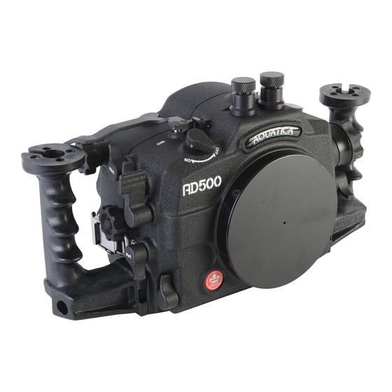
- Page 1 AD500 INSTRUCTION MANUAL Product #20080...
- Page 2 Thank you for purchasing your Aquatica AD500 housing. Before you start to use your new housing, please read these instructions carefully. Keep this manual in a safe place for future reference. This instruction manual assumes that the camera user is already familiar with the Nikon D500 camera.
-
Page 3: Table Of Contents
Vacuum pump ..................18 Flash triggering ................20 Aqua View finder ................21 Care and maintenance ................22 Housing components ..............22 Sacrificial anodes ................22 O-rings ..................22 Storage and transportation ..............24 Warranty ..................25 Table of contents AD500 INSTRUCTION MANUAL... -
Page 4: Safety Precautions
Never handle the housing by grabbing the port, or if using one, the Aqua View finder. Make sure that boat staff are familiar with these procedures and advise them to manipulate the housing by using the grips provided with the housing. AD500 INSTRUCTION MANUAL Safety precautions... -
Page 5: Product Specifications
Supplied with the Surveyor moisture and alarm vacuum sensor alarm. Compatible with the following depending on flash option: Flash capability Optical triggering Nikonos-style bulkhead Ikelite-style bulkhead Note that all of the AE-M1II flash triggering options are not TTL compatible. Product specifications AD500 INSTRUCTION MANUAL... -
Page 6: Package Contents
Package contents AD500 housing Handle grips (2) with screws (2) AD500 instruction manual Lens chart Spare housing seal O-ring CR 2032 coin cell battery Aquatica O-ring lubricant container Set of Allen keys Optical Flash trigger with optical bulkheads or double Nikonos connector... -
Page 7: Housing Schematics
AF-ON Lever Control Rear Dial Control Aquatica Stainless Steel Latch 10 On/Off Control Knob 11 Record Control Lever 12 Exposure Compensation Control Leaver 13 Shutter Release Lever 14 Front Dial Control 15 FN1 Control Lever Housing schematics AD500 INSTRUCTION MANUAL... -
Page 8: Housing Functions
22 LV Button 35 OK Button 23 Live View Switch Selector Knob 36 FN2 Button 24 Help Button 25 LCD Monitor Window Port 26 Removable Viewfinder Eye Piece 27 Mode Dial Knob 28 Trash Button AD500 INSTRUCTION MANUAL Housing schematics... - Page 9 37 AF Point Selection Button 38 MODE Button 39 QUAL Button 40 16mm/.5 Inch Accessory Port 41 White Balance Control Lever 42 Zoom/ Focus Knob 43 Lens Release Control Lever 44 AF/M Selector Knob Housing schematics AD500 INSTRUCTION MANUAL...
-
Page 10: Housing Preparation
Housing preparation Follow these steps to prepare your AD500 housing for use: STEP 1: Assemble your handle grips onto your housing using the provided screws and Allen keys. STEP 2: If you are adding any shoes, brackets or ball mounts onto your housing, mount them using the intended ¼-20 UNC threaded holes. -
Page 11: Camera Preparation And Installation
Lens Release (43), AF/M (44) and Zoom/ Focus Knob (42) located on the left of the housing as well as the FN 1 Control lever (15) located on the Right. Camera preparation and installation 11 | AD500 INSTRUCTION MANUAL... - Page 12 Before closing the housing align the AF/F (44), Lens Release (43) and FN1 (15) controls with the ones on the camera switch positions. And make sure that the ON/OFF lever (10) is working properly. 12 | AD500 INSTRUCTION MANUAL Camera preparation and installation...
- Page 13 In the event that you feel any unusual resistance when attempting to close the rear door, do not force the closure. Reopen, inspect carefully for any potential obstruction such as ON/OFF switch position and try again. Camera preparation and installation 13 | AD500 INSTRUCTION MANUAL...
-
Page 14: Port Mounting
Port mounting The AD500 housing is equipped with a bayonet locking system that firmly attaches compatible ports and extensions. STEP 1: Before mounting the port, remove the O-ring seal from its groove and carefully verify that the O-ring and its groove are free from scratches or foreign matter. -
Page 15: Port Removal
Port removal STEP 1: Press the port release lever (2) and rotate the port or extension counter clockwise. STEP 2: Carefully pull the port or extension off the bayonet. Port removal 15 | AD500 INSTRUCTION MANUAL... -
Page 16: Accessories
Accessories Surveyor sensor Your AD500 housing comes standard with the Surveyor moisture alarm. This sensor device has two distinct purposes, a moisture detection circuitry and an ambient pressure sensor circuitry; both are integrated on the same circuit board. A CR 2032 coin cell battery is provided to power your moisture alarm. - Page 17 Water detected Water is making contact with probe Everything is OK, just stop pumping vacuum. Indication of a slow leak behavior. Alarm will stay on during 30 seconds before going back to standby mode. Accessories 17 | AD500 INSTRUCTION MANUAL...
-
Page 18: Vacuum Pump
If your pump was not factory installed or bought separately, you will need to install the pressure valve bulkhead on your housing. The AD500 is compatible with pump kit #19228 and pump kit #19233. Using the proer adapters, both can be installed in the 16mm/.5”... - Page 19 If your housing fails to maintain a constant vacuum, proceed a thorough inspection of the user serviceable O-rings of the housing. If unsuccessful in determining the source of the leak, refrain from immersing the housing and return it to your authorized service center for inspection. Vacuum pump 19 | AD500 INSTRUCTION MANUAL...
-
Page 20: Flash Triggering
Both options come already wired with the required flash circuit board. All switches must be in the OFF (lower) position on the switchboard. NOTE: Note that none of the offered flash triggering options on the AD500 housing are TTL compatible. 20 |... -
Page 21: Aqua View Finder
Aqua View finder The AD500 housing is compatible with both the 180° Aqua View finder (#20054) and the 45° Aqua View finder (#20059). To install your Aqua View finder, you will have to remove the standard eyepiece. To remove your standard eyepiece: STEP 1: Using an O-ring removal tool, remove the eyepiece retaining O-ring. -
Page 22: Care And Maintenance
Never use a sharp instrument when removing an O-ring as this may damage the sealing surface of the groove or the O-ring itself. A dedicated O-ring tool, a dull pointed object or the edge of a credit card usually works well. 22 | AD500 INSTRUCTION MANUAL Care and maintenance... - Page 23 O-ring. This test, though time consuming and often considered unnecessary, may save your camera equipment from irreparable water damage. Care and maintenance 23 | AD500 INSTRUCTION MANUAL...
-
Page 24: Storage And Transportation
Failure to follow this recommendation may cause an internal pressure build up which could potentially force ports or acrylic windows to pop out or potentially unseat their O- ring seal. 24 | AD500 INSTRUCTION MANUAL Storage and transportation... -
Page 25: Warranty
Aquatica Digital 3025 De Baene Montreal (Quebec) H4S 1K8 Mark clearly on your package “Canadian goods returned for repair”. Do not ship by any other means. Unauthorized packages will be refused. YOUR SERIAL NUMBER _______________________________ Warranty 25 | AD500 INSTRUCTION MANUAL...
Need help?
Do you have a question about the AD500 and is the answer not in the manual?
Questions and answers