Table of Contents
Advertisement
Quick Links
Advertisement
Table of Contents

Related Manuals for Aquatica Digital AR5


Summary of Contents for Aquatica Digital AR5
- Page 1 INSTRUCTION MANUAL Product #20091...
- Page 2 Thank you for purchasing your Aquatica AR5 housing. Before you start to use your new housing, please read these instructions carefully. Keep this manual in a safe place for future reference. This instruction manual assumes that the camera user is already familiar with the CANON EOS-R5 camera.
-
Page 3: Table Of Contents
Table of contents Table of contents ................3 Safety precautions ................4 Product specifications ..............5 Package contents................6 Housing schematics ................. 7 Housing components ................7 Housing preparation ..............10 Camera Installation ............... 11 Port Mounting For EF Lens ............. 13 Port Mounting For RF Lens ............. -
Page 4: Safety Precautions
Safety precautions Please carefully read and follow the following precautions and recommendations: Improper transportation, handling or use of this housing might cause a flood or a malfunction. Follow all recommendations stated in the next sections of this manual. Never remove, change a port or open the housing in a location where sand or similar foreign material might come in contact with an O-ring. -
Page 5: Product Specifications
Optical triggering Nikonos-style bulkhead Ikelite-style bulkhead Note that all of the AR5 flash triggering options are not TTL compatible. Product specifications A R 5 I N S T R U C T I O N M A N U A L... -
Page 6: Package Contents
Package contents AR5 housing Handle grips (2) with screws (2) AR5 instruction manual Lens chart Spare housing seal O-ring CR 2450 coin cell battery (for Surveyor) Aquatica O-ring lubricant container Set of Allen keys Optical flash trigger (for 20091-OPT and 20091-OPT-VC kits) -
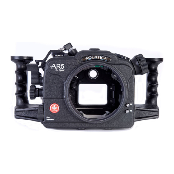
Page 7: Housing Schematics
Housing schematics Housing components Handle grips (2) Closing latches (2) Ball mounts Top ball mount Tripod mount 16mm ports (2) Flash bulkheads Zinc anodes (2) Rubber pads (4) All mounts are using ¼-20 UNC threads. Bulkheads Plugs shown. Housing schematics A R 5 I N S T R U C T I O N M A N U A L... - Page 8 Housing Function (See table on next page) Housing schematics A R 5 I N S T R U C T I O N M A N U A L...
- Page 9 Multicontrol up ON-OFF Lever AF Point Select Button Quick Control Dial 2 Multicontrol Right Zoom-Focus Wheel Info Button Movie Shooting Button Set Button M-FN mode Button Quick Control Button AF-ON start Button Alarm LED window Quick Control Dial 1 Multicontrol Down Mode Button Multicontrol Center Main Dial...
-
Page 10: Housing Preparation
Housing preparation Follow these steps to prepare your AR5 housing for use: STEP 1: Assemble your handle grips onto your housing using the provided screws (x2) and Allen key. STEP 2: If you are adding any shoes, brackets or ball mounts onto your housing, mount them using the intended ¼-20 UNC threaded holes. -
Page 11: Camera Installation
STEP 3: Mount your strobes and their arms onto the housing. For details about optical flash triggering and wired bulkheads, refer to the Accessories, Flash triggering section (page 28). Follow your strobe manufacturer manual recommendations. STEP 4: Before use, remove the main O-ring seal from its groove on the front half of the housing and carefully verify that the O-ring and its groove are free from scratches or foreign matter. - Page 12 NOTE: If you are using an optical flash triggering, install your flash trigger on your camera by following the procedure outlined in the Accessories, Flash triggering section (page 27). STEP 3: Make sure to align the camera stoppers (x2) with the LCD side of the camera when installing (2).
-
Page 13: Port Mounting For Ef Lens
Perform a check by pulling on the saddle to ensure it is firmly attached to the housing. Port Mounting For EF Lens The AR5 housing is equipped with a EF adaptor extension ring for EF lens bayonet locking system that firmly attaches compatible ports and extensions. STEP 1: Before mounting the port, remove the O-ring seal from its groove and carefully verify that the O-ring and its groove are free from scratches or foreign matter. - Page 14 STEP 3: Place the adaptor EF extension ring inside the housing bayonet. Align the bayonet using the four alignment notches in the housing. STEP 4: Push with even force on both sides of the EF adaptor extension ring until you feel it snap into place.
-
Page 15: Port Mounting For Rf Lens
EXTENSION RING ARE BOTH ROTATED CLOCKWISE AT THEIR MAXIMUM POSITION FOR THE BEST ALIGNMENT OF THE DOME SHADES. Port Mounting For RF Lens The AR5 housing is equipped with a bayonet locking system that firmly attaches compatible RF ports and extensions. STEP 1: Before mounting the port, remove the O-ring seal from its groove and carefully verify that the O-ring and its groove are free from scratches or foreign matter. - Page 16 STEP 3: Place the port or extension ring inside the housing bayonet. Align the bayonet using the four alignment notches in the housing. STEP 4: Push with even force on both sides of the port or extension ring until you feel it snap into place.
-
Page 17: Port Removal
Port Removal STEP 1: While pressing the port release lever, rotate the port or extension ring counter- clockwise until it stops. STEP 2: Carefully pull the port or extension ring out of the housing. -
Page 18: Housing Closing
Housing Closing STEP 1: Before closing the housing, remove the O-ring seal from its groove and carefully verify that the O-ring and its groove are free from scratches or foreign matter. Lubricate the O-ring with a light coat of silicone grease. Also check that the O- ring mating surface on the housing is clean and free of any physical damage. - Page 19 STEP 6: Set the camera to the OFF position and align the ON-OFF lever in the OFF position as well. IMPORTANT STEP 7: Pull the Quick Control Dial 1 towards the outside of the housing. Do not apply excessive force. Stop pulling when the stopper will not allow any more pulling. STEP 6: Align the rear portion of the housing with the front one using the two guiding pins.
- Page 20 STEP 8: Once both portions of the housing are pressed against each other, rotate latch towards the front until it catches the front hook, and then pull back until it locks into position. Repeat for second latch. WARNING: In the event that you should feel any unusual resistance when attempting to close your housing, do not force closure.
-
Page 21: Housing Opening
Housing Opening NOTE: If your housing is under vacuum, you won’t be able to open it directly with the following procedure. See note in Accessories, Vacuum pump section. STEP 1: Unlock both latches by pressing the locking tabs and pulling them out. STEP 2: Rotate both latches to free them from the front hooks and pull out the rear portion. -
Page 22: Accessories
Accessories Surveyor sensor Your AR5 housing comes standard with the Surveyor moisture alarm. This sensor device has two distinct purposes, a moisture detection circuitry and an ambient pressure sensor circuitry. NOTE: Once a battery is installed, the moisture detector function of the Surveyor alarm will remain on standby and does not need to be activated. - Page 23 LED is off Standby mode System is on standby Red LED flashing with audible alarm Water detected Water is making contact with probe Moisture alarm mode LED code : If you want to benefit from the full capabilities of your Surveyor sensor, you can order the optional vacuum pump system (#19228).
-
Page 24: Vacuum Pump
Vacuum pump A vacuum pump will allow you to fully benefit from the capabilities of your Surveyor sensor. Your pump kit (either #19228 or #19233) includes the following parts: Vacuum pump Pressure valve Retaining nut Aquatica lubricant If your pump was not factory installed or bought separately, you will need to install the pressure valve bulkhead on your housing in the rear ½”... - Page 25 To install your valve: STEP 1: Remove the existing plug by unscrewing the hexagonal nut inside. STEP 2: Lubricate the valve bulkhead O-ring using provided Aquatica O-ring lubricant (see Care and maintenance, O-rings section at page 33 for more information). STEP 3: Carefully insert the valve bulkhead into the selected port, slightly rotating the valve while pushing will facilitate the insertion.
- Page 26 To use your vacuum monitoring system: STEP 1: Prior to closing your housing, put your Surveyor sensor in vacuum mode by pressing the activation switch on the board (#3 on page 22). The Surveyor green LED should be flashing rapidly upon activation. STEP 2: Close your housing using procedure outlined in the section Housing Closing (page 18).
- Page 27 GRAP HERE SLOW AND STEADY PUMPING STEP 8: Build vacuum inside your housing by pumping the handle (#7). Pump the handle at a constant and steady rate (there is no need for excessive force or speed). The amount of pumping required will vary according to the housing dimensions and the port configuration being used.
-
Page 28: Flash Triggering
Nikonos-style bulkhead (#20091-NK and #20091-NK-VC) Ikelite-style bulkhead (#20091-KM and #20091-KM-VC) NOTE: Note that not all of the offered flash triggering options on the AR5 housing are TTL compatible. An Ikelite DL5 external converter (#46074) is required for TTL functionality. Purchased separately from Ikelite For Nikonos and Ikelite style bulkheads, simply insert the velcroed board inside your camera hot-shoe. - Page 29 If your housing is equipped with the optical flash option, you will need to use a provided optical flash trigger. STEP 1: Remove the battery trays from the flash trigger STEP 2: Insert the provided CR 2045-coin cell batteries inside the 2 battery trays (positive side up).
-
Page 30: Aqua View Finder
Aqua View finder The AR5 housing is compatible with both the 180° Aqua View finder (#20054) and the 45° Aqua View finder (#20059). To install your Aqua View finder, you will have to remove the standard eyepiece. To remove your standard eyepiece: STEP 1: Using an O-ring removal tool, remove the eyepiece retaining O-ring (#1). - Page 31 To install your Aqua View finder: STEP 1: Carefully verify that the O-ring and its groove are free from scratches or foreign matter. Lubricate the O-ring with a light coat of silicone grease. Also check that the O-ring mating surface on the housing is clean and free of any physical damage.
-
Page 32: Care And Maintenance
WARNING: It is highly recommended to perform a simple seal test without the camera after performing the installation. View following section for details. Care and maintenance With basic care and a regular maintenance schedule, your Aquatica housing will provide years of enjoyment and satisfaction in producing spectacular underwater images. -
Page 33: O-Rings
O-rings When replacing the main seal O-ring, place the entire O-ring over the O-ring groove and start by pushing the O-ring in the corners. Work your way around the O-ring making sure it is snugly sitting in the groove. Avoid going solely in one direction as doing so will stretch the O-ring material and possibly prevent it from properly seating. -
Page 34: Storage And Transportation
The internal O-rings of the housing are not user replaceable. While these O-rings are not as susceptible to damage as the main seal, rinsing the housing properly with fresh water to flush out salt crystals and sand residues will assure trouble free operation. Aquatica recommends yearly maintenance of the internal O-rings. -
Page 35: Warranty
To obtain service during or after the warranty period you must notify Aquatica at +1 (514) 737-9481 and ship by registered mail (insured) only, enclosing your proof of purchase to: Aquatica Digital 3025 De Baene Montreal (Quebec) H4S 1K8 Mark clearly on your package “Canadian goods returned for repair”.
Need help?
Do you have a question about the AR5 and is the answer not in the manual?
Questions and answers