Table of Contents
Advertisement
Quick Links
Advertisement
Table of Contents

Subscribe to Our Youtube Channel
Related Manuals for Aquatica Digital AGH5


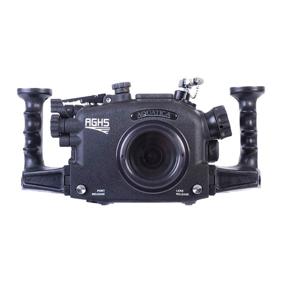
Summary of Contents for Aquatica Digital AGH5
- Page 1 AGH5 INSTRUCTION MANUAL Product #35000...
- Page 2 Thank you for purchasing your Aquatica AGH5 housing. Before you start to use your new housing, please read these instructions carefully. Keep this manual in a safe place for future reference. This instruction manual assumes that the camera user is already familiar with the Panasonic GH5 camera.
-
Page 3: Table Of Contents
Table of contents Table of contents ..................3 Safety precautions ..................4 Product specifications ..................5 Package contents ..................6 Housing schematics ..................7 Housing preparation ..................9 Camera preparation and installation ..............11 Port mounting .................... 14 Port removal ....................15 Housing closing ................... -
Page 4: Safety Precautions
Safety precautions Please carefully read and follow the following precautions and recommendations: Improper transportation, handling or use of this housing might cause a flood or a malfunction. Follow all recommendations stated in the next sections of this manual. Never remove, change a port or open the housing in a location where sand or similar foreign material might come in contact with an O-ring. -
Page 5: Product Specifications
Optical triggering Nikonos-style bulkhead Ikelite-style bulkhead Note that all of the AGH5 flash triggering options are not TTL compatible. A G H 5 I N S T R U C T I O N M A N U A L... -
Page 6: Package Contents
Package contents AGH5 housing Handle grips (2) with screws (2) AGH5 instruction manual Lens chart Spare housing seal O-ring CR 2032 coin cell battery (for Surveyor) Aquatica O-ring lubricant container Set of Allen keys Slim flash trigger (for 35000-OPT and 35000-OPT-VC kits) -
Page 7: Housing Schematics
Housing schematics Housing components Handle ball mounts(4) Top 16 mm port Flash port Top ball mount ½” port Bottom 16 mm port Zinc anodes(2) Tripod mount Eyepiece Closing latch Surveyor LED For HDMI bulkhead Options: Optical (shown in figure), Nikonos, or Ikelite (page24) Accepts ½”... - Page 8 Housing controls Port release Lens release White balance lever ISO lever Exposure compensation button Fn1 button Mode dial Mode lock button On/Off switch Drive mode dial Zoom/Focus dial Fn5 button Playback button Disp. button Fn2 Q.MENU button Fn3 Autofocus mode button Menu/Set –...
-
Page 9: Housing Preparation
Housing preparation Follow these steps to prepare your AGH5 housing for use: STEP 1: Assemble your handle grips (2) onto your housing (1) using the provided screws (3) and Allen keys. STEP 2: adding shoes, brackets or ball mounts onto your housing, mount them using the intended ¼-20 UNC threaded holes. - Page 10 WARNING: For proper handling of O-rings, follow the detailed instructions outlined in the O- rings section (page 28). STEP 5: Insert the provided CR 2032 coin cell battery in the Surveyor alarm as described in the, Surveyor sensor section (page 19). 10 | A G H 5 I N S T R U C T I O N M A N U A L...
-
Page 11: Camera Preparation And Installation
Camera preparation and installation Follow these steps to prepare your Panasonic GH5 camera for use with your housing. To save valuable time underwater it is also advisable before inserting the camera into the housing, to set your camera shooting preferences beforehand. STEP 1: Remove the camera rubber eye cup and the two shoulder strap eyelets. - Page 12 STEP 3: [OPTIONAL] If you wish to take full advantage of your Panasonic GH5 camera underwater, you can remap your camera Dials and Fn buttons to best fit your shooting style and maximize ergonomics. To access dial remapping: Note: The housing dial mechanisms reverse direction of the camera dials.. If you want to keep using your dials in the direction you are used to on land, you can also reverse the dial direction in these settings.
- Page 13 STEP 6: Install the camera on the saddle by aligning the threaded hole under the camera and screwing the bottom screw with either a flat screwdriver or a coin. NOTE: If you are using an optical flash triggering, install your flash trigger on your camera by following the procedure outlined in the Flash triggering section STEP 7: Slide the saddle and camera inside the housing using the two guiding pins.
-
Page 14: Port Mounting
Port mounting The AGH5 housing is equipped with a bayonet locking system that firmly attaches compatible ports and extensions. STEP 1: Before mounting the port, remove the O-ring seal from its groove and carefully verify that the O-ring and its groove are free from scratches or foreign matter. -
Page 15: Port Removal
Port removal STEP 1: While pressing the port release button, rotate the port or extension ring counter- clockwise until it stops. STEP 2: Carefully pull the port or extension ring out of the housing. 15 | A G H 5 I N S T R U C T I O N M A N U A L... -
Page 16: Housing Closing
Housing closing STEP 1: Before closing the housing, remove the O-ring seal from its groove and carefully verify that the O-ring and its groove are free from scratches or foreign matter. Lubricate the O-ring with a light coat of silicone grease. Also check that the O- ring mating surface on the housing is clean and free of any physical damage. - Page 17 NOTE: All the control mechanisms in your AGH5 housing are self-aligning. This means you don’t have to worry about matching the lever positions on your camera and your housing. However, note that if the control levers on your housing are not matching those of your camera upon closing, you may need to cycle them one time.
-
Page 18: Housing Opening
Housing opening NOTE: If your housing is under vacuum, you won’t be able to open it directly with the following procedure. See note in the Vacuum pump section. STEP 1: While pressing the release tab, rotate the locking latch counter-clockwise. NOTE: The latch is shown in its initial locked position. -
Page 19: Accessories
Accessories Surveyor sensor Your AGH5 housing comes standard with the Surveyor moisture alarm. This sensor device has two distinct purposes, a moisture detection circuitry and an ambient pressure sensor circuitry. NOTE: Once a battery is installed, the moisture detector function of the Surveyor alarm will remain on standby and does not need to be activated. - Page 20 Moisture alarm mode LED code: LED is off Standby mode System is on standby Red LED flashing with audible alarm Water detected Water is making contact with probe If you want to benefit from the full capabilities of your Surveyor sensor, you can order the optional vacuum pump system (#19228).
- Page 21 Vacuum pump A vacuum pump will allow you to fully benefit from the capabilities of your Surveyor sensor. Your pump kit (either #19228 or #19233) includes the following parts: Vacuum pump Pressure valve Retaining nut Aquatica lubricant If your pump was not factory installed or bought separately, you will need to install the pressure valve bulkhead on your housing.
- Page 22 To use your vacuum monitoring system: STEP 1: Prior to closing your housing, put your Surveyor sensor in vacuum mode by pressing the activation switch on the board (#3 on page 19). The Surveyor green LED should be flashing rapidly upon activation. STEP 2: Close your housing as outlined in the Housing closing section page 16.
- Page 23 WARNING: Be careful not to over-depressurize the housing. This will trigger the alarm and require the sensor to be reset. STEP 7: Remove the pump by sliding the quick-disconnect collar (2) and put back the plug (1) in the pressure valve. If your housing fails to maintain a constant vacuum, proceed a thorough inspection of the user serviceable O-rings of the housing.
- Page 24 Nikonos-style bulkhead (2,5,6) (#35000-NK and #35000-NK-VC) Ikelite-style bulkhead (3,5,6) (#35000-IKE and #35000-IKE-VC) NOTE: Note that none of the offered flash triggering options on the AGH5 housing are TTL compatible. For Nikonos (2) and Ikelite (3) style bulkheads, simply insert the velcroed board (5) inside your camera hot-shoe.
- Page 25 If your housing is equipped with the optical flash option, you will need to use the provided slim flash trigger (#18958). STEP 1: Remove the battery tray (#2) from the flash trigger (#1). STEP 2: Insert the provided CR 2016 coin cell batteries (#3) inside the battery tray (#2).
- Page 26 Aqua View finder The AGH5 housing is compatible with both the 180° Aqua View finder (#20054) and the 45° Aqua View finder (#20059). To install your Aqua View finder, you will have to remove the standard eyepiece. To remove your standard eyepiece: Note: housing shown in this section are not the AGH5, figures are for reference only.
- Page 27 To install your Aqua View finder: STEP 1: Carefully verify that the O-ring and its groove are free from scratches or foreign matter. Lubricate the O-ring with a light coat of silicone grease. Also check that the O-ring mating surface on the housing is clean and free of any physical damage.
-
Page 28: Care And Maintenance
Care and maintenance With basic care and a regular maintenance schedule, your Aquatica housing will provide years of enjoyment and satisfaction in producing spectacular underwater images. Please follow all undermentioned care and maintenance instructions. Housing components After every salt water dive, soak and/or rinse your housing system in fresh water. It should soak for a minimum of 30 minutes. - Page 29 Wipe the matching sealing surface part of the housing with a clean lint-free cloth. Lubricate the O-ring with a thin layer of Aquatica O-ring lubricant (# 19213) until it appears to be smooth and shiny. Do not over lubricate. Use just enough lubricant so the O-ring will pull smoothly through your fingers.
-
Page 30: Storage And Transportation
Storage and transportation Store and transport the housing in a sturdy, shock proof container and avoid travelling with the camera mounted inside the housing. In the event of an impact, especially on the external push buttons, the impact could potentially be transferred to the camera controls and damage them. -
Page 31: Warranty
To obtain service during or after the warranty period you must notify Aquatica at +1 (514) 737-9481 and ship by registered mail (insured) only, enclosing your proof of purchase to: Aquatica Digital 3025 De Baene Montreal (Quebec) H4S 1K8 Mark clearly on your package “Canadian goods returned for repair”.
Need help?
Do you have a question about the AGH5 and is the answer not in the manual?
Questions and answers