Sign In
Upload
Download
Table of Contents
Contents
Add to my manuals
Delete from my manuals
Share
URL of this page:
HTML Link:
Bookmark this page
Add
Manual will be automatically added to "My Manuals"
Print this page
×
Bookmark added
×
Added to my manuals
Manuals
Brands
Siemens Manuals
Security Sensors
OH720
Technical manual
Siemens OH720 Technical Manual
Automatic fire detectors
Hide thumbs
1
2
Table Of Contents
3
4
5
6
7
8
9
10
11
12
13
14
15
16
17
18
19
20
21
22
23
24
25
26
27
28
29
30
31
32
33
34
35
36
37
38
39
40
41
42
43
44
45
46
47
48
49
50
51
52
53
54
55
56
57
58
59
60
61
62
63
64
page
of
64
Go
/
64
Contents
Table of Contents
Bookmarks
Table of Contents
Table of Contents
1 About this Document
Applicable Documents
Download Center
Technical Terms
History of Changes
2 Safety
Safety Instructions
Safety Regulations for the Method of Operation
Standards and Directives Complied with
Release Notes
3 Structure and Function
Overview
Details for Ordering
Product Version es
Point Detector
Multi-Sensor Smoke Detector
Smoke Detector
Heat Detector
Function
Parameter Sets
Danger Levels
Diagnosis Levels
Line Separator
Internal Alarm Indicator in the Case of es <10
Extended Flashing Behavior of Alarm Indicators in the Case of
Connection for External Alarm Indicators
Test Mode
Behavior in Degraded Mode
Line Tester
Mechanical Setup
Accessories
Detector Base with Loop Contact DB721
Detector Base DB722
Detector Base DB720
Sounder Base DBS720
Designation Plate FDBZ291
Detector Base Seal RS720
Base Attachment BA720
Base Attachment Wet BA721
Designation Plate DBZ1193A
Detector Heating Unit FDBH291
Protective Cage DBZ1194
Detector Locking Device LP720
Micro Terminal DBZ1190-AA
Connection Terminal DBZ1190-AB
4 Planning
Compatibility
Multi-Sensor Smoke Detector
Parameter Sets
Specifications
Smoke Detector
Parameter Sets
Specifications
Heat Detector
Parameter Sets
Specifications
5 Mounting / Installation
Required Space
Detector Base Db72X
Sounder Base DBS720
Detector Base Seal RS720
Base Attachment BA720
Base Attachment Wet BA721
Detector Locking Device LP720
Designation Plate FDBZ291
Cable Entry
Auxiliary Terminals DBZ1190-AA/-AB
Detector Lines
Connection Diagram, Addressed
Detector Dust Cap
Detector Heating Unit FDBH291
Installation of the Detector Heating Unit
Connection of the Detector Heating Unit
6 Commissioning
Commissioning on the C-NET
7 Maintenance / Repair
Performance Check
Testing Detectors
8 Specifications
Multi-Sensor Smoke Detector Technical Data
Smoke Detector Technical Data
Heat Detector Technical Data
Dimensions
Environmental Compatibility
Index
Advertisement
Quick Links
1
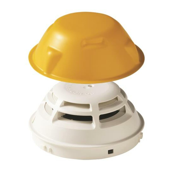
Smoke Detector
Download this manual
OH720, OP720, HI720, HI722
Automatic fire detectors
Technical Manual
A6V10212047_m_en_--
2015-05-04
Building Technologies
Control Products and Systems
Table of
Contents
Previous
Page
Next
Page
1
2
3
4
5
Advertisement
Table of Contents
Need help?
Do you have a question about the OH720 and is the answer not in the manual?
Ask a question
Questions and answers
Related Manuals for Siemens OH720
Security Sensors Siemens OP720 Technical Manual
Automatic fire detectors (64 pages)
Security Sensors Siemens OH110 Technical Manual
Automatic fire (60 pages)
Security Sensors Siemens OP110 Technical Manual
Automatic fire (60 pages)
Security Sensors Siemens OOH740-A9-Ex Technical Manual
Automatic fire detector (72 pages)
Security Sensors siemens FDOOT241-A9-Ex Technical Manual
Neural fire detector (26 pages)
Security Sensors Siemens OOH740 Technical Manual
Automatic fire detectors (108 pages)
Security Sensors Siemens OOH740 Technical Manual
Automatic fire detectors (88 pages)
Security Sensors Siemens OOH941 Installation Instructions Manual
Multi-criteria fire detector ul268 7th edition listed (8 pages)
Security Sensors Siemens Cerberus PRO OH720 Manual
Automatic fire detectors (12 pages)
Security Sensors Siemens Sinteso FD20 Product Data
(152 pages)
Security Sensors Siemens Cerberus CS1140 Commissioning
Fire detection system (112 pages)
Security Sensors Siemens FDOOT441 Installation Instructions Manual
Multi-criteria fire detector (8 pages)
Security Sensors Siemens DB-11 Installation/Wire Connection Manual
Detector base (2 pages)
Security Sensors Siemens GM730 Installation Manual
Seismic detector (3 pages)
Security Sensors Siemens LAE10 Quick Manual
Flame safeguards (9 pages)
Security Sensors Siemens venteville Sinteso FDOOT241-A3 Manual
Multisensor fire detectors (10 pages)
This manual is also suitable for:
Op720
Hi720
Hi722
Table of Contents
Save PDF
Print
Rename the bookmark
Delete bookmark?
Delete from my manuals?
Login
Sign In
OR
Sign in with Facebook
Sign in with Google
Upload manual
Upload from disk
Upload from URL


Need help?
Do you have a question about the OH720 and is the answer not in the manual?
Questions and answers