Table of Contents
Advertisement
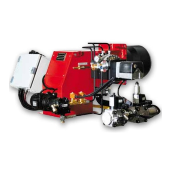
GAS BURNERS
BLU TS 3000.1 PR HT
BLU TS 4000.1 PR HT
Technical data
Operating instructions
Electric diagrams
Spare parts list
Gas train manual is separate
BLU TS 3000.1 PR TC SGT HT 230-50
BLU TS 3000.1 PR TL SGT HT 230-50
BLU TS 4000.1 PR TC SGT HT 230-50
BLU TS 4000.1 PR TL SGT HT 230-50
12-02-2016
www.ecoflamburners.com
EN
3143084
3143198
Advertisement
Table of Contents


Need help?
Do you have a question about the BLU TS 3000.1 PR HT and is the answer not in the manual?
Questions and answers