Datalogic Gryphon GBT4400 Quick Reference Manual
General purpose handheld area imager bar code reader with bluetooth wireless technology
Hide thumbs
Also See for Gryphon GBT4400:
- Product reference manual (332 pages) ,
- Quick reference manual (68 pages) ,
- Product reference manual (350 pages)

Related Manuals for Datalogic Gryphon GBT4400


Summary of Contents for Datalogic Gryphon GBT4400
- Page 1 Gryphon™ I GBT4400 General Purpose Handheld Area Imager Bar Code Reader with Bluetooth® Wireless Technology Quick Reference Guide...
- Page 2 U.S.. The Bluetooth word mark and logos are owned by Bluetooth SIG, Inc. and any use of such marks by Datalogic Group companies is under license. All other brand and product names may be trade- marks of their respective owners Patents www.patents.datalogic.com...
-
Page 3: Table Of Contents
Replacing the Batteries ............ 17 Using the Gryphon™ I GBT4400 ..........19 Linking the Reader ..............20 Link Datalogic RF Devices to Base......20 Link Scanner to Bluetooth Adapter ....... 20 Power Off ..................21 Selecting the Interface Type ............. 21 Interface Selection ............ - Page 4 Base Station Indications ............45 Datalogic Limited Factory Warranty ....... 46 Ergonomic Recommendations ..........48 Support Through the Website ..........49 Gryphon™ BT4400...
-
Page 5: End User Software License Agreement (Eula)
This EULA (End User Software License Agreement) ("EULA” or "Agreement") is a legally binding agreement governing the licensing of the Software and Documenta- tion by Datalogic IP Tech S.r.l. and its subsidiaries and affiliates ("Datalogic") to the entity or person who has purchased or otherwise acquired a Datalogic Product ("End User"). - Page 6 United States copyright law and trade secret law, and by all applicable international intellectual property laws and treaty provisions. The license set forth in this Agree- ment does not transfer to End User any ownership of Datalogic's or its third party licensors' copyrights, patents, trademarks, service marks, trade secrets, or other intellectual property rights and End User shall have no right to commence any legal actions to obtain such rights.
- Page 7 52.227-14(g), or 52.227-19 or in the Rights in Technical Data and Computer Software clause at DFARS 252.227-7013(c)(1)(ii), whichever is applicable. If End User is using the Datalogic Product outside of the United States, End User must comply with the applicable local laws of the country in which the Datalogic Product is used, with U.S.
-
Page 8: Software Product Policy
State of Oregon located in either Multnomah or Lane counties shall have exclusive jurisdiction over all matters regarding this Agreement, except that Datalogic shall have the right, at its absolute discretion, to initi- ate proceedings in the courts of any other state, country, or territory in which End User resides, or in which any of End User's assets are located. -
Page 9: Description
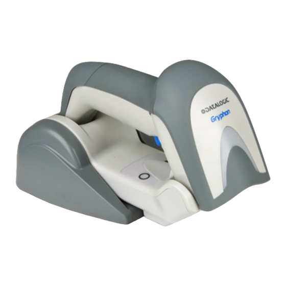
Gryphon™ I GBT4400 Description With rich feature sets and extensive options, the Gryphon™ product series from Datalogic represents the premium level of data collection equipment for general purpose applications. The Gryphon GBT4400 readers have enhanced optics with improved motion tolerance allowing codes placed on fast... -
Page 10: Setting Up The Reader
* that battery packs of the stocked products NOTE GBT/GM44 and spare battery pack parts must be periodically recharged : for instance by using a BC40xx cradle powered up with a 12V Datalogic AC/DC adapter (cod.8-0935) for at least 30 minutes each 3 months. Gryphon™ GBT4400... -
Page 11: Positioning The Base Station
Positioning the Base Station Positioning the Base Station The base station/charger may be set up in desk application to hold the reader in three different positions, either a horizontal or standing or vertical position, in order to provide the most comfortable use depending on the needs. - Page 12 Positioning the Base Station Figure 3 - Vertical Position This position is preferred when lack of room on the desktop recommends the scanner to be left vertical during recharging. Insert the appropriate parts for the desired base sta- tion position. Using your thumbs, push open the plastic tabs on the bottom of the base to free the wing holders.
- Page 13 Positioning the Base Station To ensure best contact and performance, do not intermix the parts of the two different mount sets. CAUTION The stand can now be repositioned in either horizontal or standing position. Horizontal Standing Quick Reference Guide...
-
Page 14: Connecting The Base Station
Connecting the Base Station Connecting the Base Station Figure 4 on page 6 shows how to connect the Base Station to a terminal, PC or other host device. Turn off the host before connection and consult the manual for that equipment (if necessary) before proceeding. - Page 15 Connecting the Base Station tal, stand or wall mount. The cables can be looped around to the front of the Base Station, or fed directly out the back of the Base Station, as shown in Figure Figure 5. Options for routing the DC cord Please refer to the arrows depicted on the bottom of the base when placing the cables, detailed in Figure...
- Page 16 Connecting the Base Station Host Connection — Verify before connection that the reader’s cable type is compatible with your host equipment. The Gryphon I GBT4400 can be set up to require a PIN code when connecting to the host. If you are adding new equipment to a system that uses a custom security PIN, please see the PRG for information before proceeding.
-
Page 17: System And Network Layout
Connecting the Base Station System and Network Layout Typical Setup with Cradle and Host Figure 9. Reader Layout Quick Reference Guide... -
Page 18: Using The Bc40Xx™ Radio Base
The button can be used to force device connection via the Datalogic Aladdin Software tool, to force a BT disconnect, and for paging the scanner when it is activated. Refer to the Gry- phon I GBT4400 Product Reference Guide (PRG) for a more detailed explanation. -
Page 19: Cleaning Procedure
Connecting the Base Station Cleaning Procedure Proper cleaning is needed on the external plastic surfaces, output window and electrical contacts to guarantee reliable scanning and charging of the battery. A regular cleaning routine will remove the dust and dirt that may accumulate on the product over time. -
Page 20: Cleaning Electrical Contact Surfaces
Connecting the Base Station Do not use abrasive or aggressive cleansing agents or abrasive pads to clean scan windows, contacts or plastics. Do not spray or pour liquids directly onto the unit. DO NOT use aerosols nor solvents. Be sure to turn off power and unplug the device from electrical outlet before cleaning. - Page 21 Connecting the Base Station Be careful when using compressed air: protect yourself with goggles and point the nozzle far from eyes and not too close to the scanner sur- face. Read previously the warning label on the spray can. CAUTION Cleaning cradle contacts •...
-
Page 22: Charging The Batteries
The LEDs on the base (shown in Table 1) will indicate the sta- tus of the battery. Before using the Battery, read “Battery Safety” in the following section. Datalogic recommends annual replacement of rechargeable battery packs to ensure maximum performance. NOTE Battery Safety To install, charge and/or perform any other action on the battery, follow the instructions in this manual. - Page 23 Charging the Batteries In the event the battery pack leaks and the fluid gets into your eye, do not rub the eye. Rinse well with water and immediately seek medical care. If left untreated, the battery fluid could cause dam- WARNING age to the eye.
- Page 24 Charging the Batteries battery, but cell manufacturers rate them at 500 charge cycles. In other words, the batteries should be expected to take 500 full discharge/charge cycles before needing replacement. This number is higher if partial discharging/ recharging is adhered to rather than full/deep discharg- ing.
-
Page 25: Replacing The Batteries
Charging the Batteries Replacing the Batteries Before proceeding, read “Battery Safety” on the preceding pages. Datalogic recommends annual replacement of rechargeable battery packs to ensure maximum performance. NOTE Use the following procedure to change the reader’s battery: With a screwdriver, unscrew the battery cover screw. - Page 26 Charging the Batteries Remove the old battery from its place (if present), and insert the new battery in the same position. Replace the battery holder cap, plug in the connector and return the contacts circuit to its previous location. When inserting the new battery into the handle, take care to position the battery and the con- nector as described above.
-
Page 27: Using The Gryphon™ I Gbt4400
LED indicator. Reference the Gryphon I GBT4400 Product Reference Guide (PRG) or Datalogic Aladdin configuration software (both avail- able on the Datalogic website) for more information about this feature and other programmable settings. Quick Reference Guide... -
Page 28: Linking The Reader
Use the host computer’s Bluetooth manager to “Dis- cover new devices” and select "Datalogic Scanner." If you receive an error message, it may be necessary to disable security on the device. -
Page 29: Power Off
Power Off Power Off Scan the bar code below to shut off power to the BT handheld until the next trigger pull. PowerOff Selecting the Interface Type Upon completing the physical connection between the reader and its host, proceed directly to Interface Selection below for information and programming for the interface type the reader is connected to (for example: RS-232, Keyboard Wedge, USB, etc.) and scan the appropriate bar code to select your... - Page 30 Selecting the Interface Type RS-232 RS-232 standard interface Select RS232-STD RS-232 Wincor-Nixdorf Select RS232-WN RS-232 for use with OPOS/UPOS/JavaPOS Select RS-232 OPOS USB COM to simulate RS-232 standard interface Select USB-COM-STD a. Download the correct USB COM driver from www.datalogic.com Gryphon™ GBT4400...
- Page 31 Selecting the Interface Type IBM-46xx Port 5B reader interface Select IBM-P5B IBM-46xx Port 9B reader interface Select IBM-P9B USB-OEM USB-OEM (can be used for OPOS/UPOS/JavaPOS) Select USB-OEM Quick Reference Guide...
-
Page 32: Keyboard Interface
Selecting the Interface Type Keyboard Interface Use the programming bar codes to select options for USB Keyboard and Wedge Interfaces. KEYBOARD AT, PS/2 25-286, 30-286, 50, 50Z, 60, 70, 80, 90 & 95 w/ Standard Key Encoding Select KBD-AT Keyboard Wedge for IBM AT PS2 with standard key encoding but without external keyboard Select KBD-AT-NK AT, PS/2 25-286, 30-286, 50, 50Z, 60, 70, 80, 90 &... - Page 33 Selecting the Interface Type KEYBOARD (continued) PC/XT w/Standard Key Encoding Select KBD-XT Keyboard Wedge for IBM Terminal 3153 Select KBD-IBM-3153 Keyboard Wedge for IBM Terminals 31xx, 32xx, 34xx, 37xx make only keyboard Select KBD-IBM-M Keyboard Wedge for IBM Terminals 31xx, 32xx, 34xx, 37xx make break keyboard Select KBD-IBM-MB USB Keyboard with alternate key encoding...
-
Page 34: Scancode Tables
Selecting the Interface Type KEYBOARD (continued) Keyboard Wedge for DIGITAL Terminals VT2xx, VT3xx, VT4xx Select KBD-DIG-VT USB Keyboard with standard key encoding Select USB Keyboard WAND EMULATION Wand Emulation Select WAND Scancode Tables Reference the Gryphon™ PRG for information about control character emulation which applies to keyboard interfaces. - Page 35 Selecting the Interface Type COUNTRY MODE ENTER/EXIT PROGRAMMING MODE Country Mode = U.S. Country Mode = Belgium Country Mode = Britain Country Mode = Croatia* *Supports only the interfaces listed in the Country Mode feature description Quick Reference Guide...
- Page 36 Selecting the Interface Type COUNTRY MODE (continued) Country Mode = Czech* Country Mode = Denmark* Country Mode = France Country Mode = Germany Country Mode = Hungary* Country Mode = Italy *Supports only the interfaces listed in the Country Mode feature description Gryphon™...
- Page 37 Selecting the Interface Type COUNTRY MODE (continued) Country Mode = Japanese 106-key* Country Mode = Norway* Country Mode = Poland* Country Mode = Portugal* Country Mode = Romania* Country Mode = Spain *Supports only the interfaces listed in the Country Mode feature description Quick Reference Guide...
- Page 38 Selecting the Interface Type COUNTRY MODE (continued) Country Mode = Sweden Country Mode = Slovakia* Country Mode = Switzerland* *Supports only the interfaces listed in the Country Mode feature description Gryphon™ GBT4400...
-
Page 39: Caps Lock State
Selecting the Interface Type Caps Lock State This option specifies the format in which the reader sends character data. This applies to keyboard wedge interfaces. This does not apply when an alternate key encoding keyboard is selected. CAPS LOCK STATE ENTER/EXIT PROGRAMMING MODE Caps Lock State = Caps Lock OFF Caps Lock State = Caps Lock ON... -
Page 40: Numlock
Selecting the Interface Type Numlock This option specifies the setting of the Numbers Lock (Num- lock) key while in keyboard wedge interface. This only applies to alternate key encoding interfaces. It does not apply to USB keyboard. NUMLOCK ENTER/EXIT PROGRAMMING MODE Numlock = Numlock key unchanged Numlock = Numlock key toggled Gryphon™... -
Page 41: Programming
Programming Programming The reader is factory-configured with a set of standard default features. After scanning the interface bar code from the Interfaces section, select other options and customize your reader through use of the programming bar codes avail- able in the Product Reference Guide (PRG). Check the corre- sponding features section for your interface, and also the Data Editing and Symbologies chapters. -
Page 42: Reading Parameters
Reading Parameters Reading Parameters Point the reader at the target and pull the trigger to enable the aiming system and the illuminator (red beam) to capture and decode the image. The aiming system will briefly switch off during the acquisition time and if no code is decoded will switch on again before the next acquisition. -
Page 43: Good Read Green Spot Duration
Reading Parameters Good Read Green Spot Duration Successful reading can be signaled by a good read green spot. Use the bar codes below to specify the duration of the good read pointer beam after a good read. GOOD READ GREEN SPOT DURATION ENTER/EXIT PROGRAMMING MODE Green Spot Duration = Disable (Green Spot is Off) Green Spot Duration = Short (300 msec) -
Page 44: Scan Modes
Scan Modes Scan Modes The imager can operate in one of several scanning modes. Trigger Single — When the trigger is pulled, scanning is acti- vated until one of the following occurs: - a programmable duration has elapsed - a label has been read - the trigger is released This mode is associated with typical handheld reader opera- tion. -
Page 45: Scan Mode
Scan Modes SCAN MODE ENTER/EXIT PROGRAMMING MODE Scan Mode = Trigger Single Scan Mode = Trigger Hold Multiple Scan Mode = Trigger Pulse Multiple Scan Mode = Flashing Scan Mode = Always On Scan Mode = Stand Mode Quick Reference Guide... -
Page 46: Pick Mode
Scan Modes Pick Mode Pick Mode is a Decoding and Transmission process where bar codes that are not within the configurable distance from the center of the aiming pattern are not acknowledged or trans- mitted to the host. It is active only while the scanner is in Trigger Single mode. -
Page 47: Technical Specifications
Technical Specifications Technical Specifications The following table contains Physical and Performance Char- acteristics, User Environment and Regulatory information. Physical Characteristics White/Gray Color Black/Gray Height 7.1”/181 mm Dimensions Length 3.9”/100 mm Width 2.8”/71 mm Approximately Weight (without 8.7 ounces/246 g (reader) cable) 8.7 ounces/246 g (base charger) Electrical Characteristics... - Page 48 Technical Specifications Depth of Field (Typical) Symbology 5mil: 1.6” -7.5” (4.0 -19cm) 3mil: 0.9” - 3.6” (2.4 - 10mil: 0.4” - 11.8” (1.0 - 9.1cm) Code 39 30cm) 5 mil: 0.3” - 4.5” (0.8 - 20mil: up to 17.7” (up to 11.3cm) 45cm) 7.5mil: 0.5”...
- Page 49 Technical Specifications Decode Capability 1D Bar Codes UPC/EAN/JAN (A, E, 13, 8); UPC/EAN/JAN (including P2 /P5); UPC/EAN/ JAN (including; ISBN / Bookland & ISSN); UPC/EAN Coupons; Code 39 (including full ASCII); Code 39 Trioptic; Code39 CIP (French Pharmaceutical); LOGMARS (Code 39 w/ standard check digit enabled); Danish PPT; Code 32 (Italian Pharmacode 39);...
- Page 50 Technical Specifications Ambient Light Immu- Up to 100,000 Lux nity Contaminants Spray/ IEC 529-IP52 (scanner only) rain Dust/particulates ESD Level 16 KV Regulatory See the Regulatory Addendum for details. Radio Features Frequency Range 2400 to 2483.5 MHz Range (in open air) 30 m a.
-
Page 51: Led And Beeper Indications
LED and Beeper Indications LED and Beeper Indications The reader’s beeper sounds and its LED illuminates to indi- cate various functions or errors on the reader. An optional“Green Spot” also performs useful functions. The fol- lowing tables list these indications. One exception to the behaviors listed in the tables is that the reader’s functions are programmable, and so may or may not be turned on. - Page 52 LED and Beeper Indications Programming Mode - The following indications ONLY occur when the reader is in Programming Mode. INDICATION DESCRIPTION BEEPER A valid programming LED blinks Reader sounds Label Programming label has been continu- four low fre- Mode Entry scanned.
-
Page 53: Base Station Indications
Base Station Indications Base Station Indications Indication LEDS Power-up Complete Yellow LED on Reader Disabled by the HOST or the communication with HOST is not Yellow LED blinking ~1Hz established Data/labels are transmitted to the Yellow LEDs turned off for HOST 100mSec Programming Mode... -
Page 54: Datalogic Limited Factory Warranty
Datalogic hardware products are war- ranted against defects in material and workmanship under normal and proper use. The liability of Datalogic under this warranty is limited to furnishing the labor and parts necessary to remedy any defect cov- ered by this warranty and restore the product to its normal operating condition. - Page 55 Datalogic. Datalogic shall assume risk of loss or damage for product in Datalogic’s possession. In the absence of specific written instruc- tions for the return of product to Customer, Datalogic will select the carrier, but Datalogic shall not thereby assume any liability in connec- tion with the return shipment.
-
Page 56: Ergonomic Recommendations
Ergonomic Recommendations Ergonomic Recommendations In order to avoid or minimize the potential risk of ergonomic injury follow the recommendations below. Consult with your local Health & Safety Manager to ensure that you are adhering to your CAUTION company’s safety programs to prevent employee injury. -
Page 57: Support Through The Website
Support Through the Website Support Through the Website Datalogic provides several services as well as technical support through its website. Log on to and click on the SUPPORT > www.datalogic.com GENERAL DUTY HANDHELD SCANNERS category link. From this page you can select your product model from the dropdown list which gives you access to: Downloads including Data Sheets, Manuals, Software &... - Page 58 Support Through the Website NOTES Gryphon™ GBT4400...
- Page 59 Support Through the Website NOTES Quick Reference Guide...
- Page 60 ©2010-2017 Datalogic S.p.A. and/or its affiliates. All rights reserved. Datalogic and the Datalogic logo are registered trademarks of Datalogic S.p.A. in many countries, including the U.S. and the E.U. Datalogic USA Inc. 959 Terry Street | Eugene, OR 97402 | U.S.A. |...
Need help?
Do you have a question about the Gryphon GBT4400 and is the answer not in the manual?
Questions and answers