Table of Contents
Advertisement
Advertisement
Table of Contents

Related Manuals for pitsco 41427


Summary of Contents for pitsco 41427
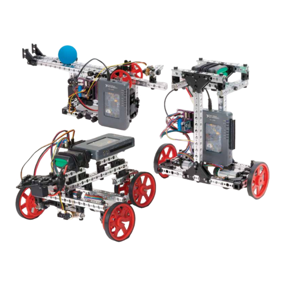
- Page 1 NI myRIO Robot Builder’s Guide POWERED BY 41427...
-
Page 3: Table Of Contents
No part of this product or related documentation may be reproduced in any form by any means without prior written authorization of Pitsco, Inc. All other product names mentioned herein might be the trademarks of their respective owners. -
Page 4: Preface
Back to Contents page Preface This builder’s guide has been developed to provide students with positive experiences in robotics engineering. With the assistance of this guide, students will learn to use the TETRIX PRIME parts and myRIO to design and construct three different robots. -
Page 5: Set Components
Back to Contents page Set Components This section documents all the parts included in the kit, including images, quantities, and part numbers. The part number of each part will match the part number noted on the label of each part bag. The part bags may contain one or more parts, and there may be more than one bag of a particular type of part. -
Page 6: Mechanical Parts
Back to Contents page Mechanical Parts 4x – 3-Way Beam Connector 40212 4x – 90-Degree Beam Connector 40211 4x – Tee Beam Connector 40213 4x – Beam End Connector 40214 4x – Beam Extension 40322 4x – Straight Beam Connector 40215 Set Components... - Page 7 Mechanical Parts 10x – 90-Degree Bracket 40208 10x – 60-Degree Bracket 40209 10x – Tee Bracket 40210 24x – Quick Rivet Peg 40220 24x – Quick Rivet Connector 40219 50x – Thumbscrew 40323 24x – Wing Nut 40221 10x – 90-Degree Cross Block Connector 40217 10x –...
- Page 8 Mechanical Parts 1x – PRIME Gripper Assembly 40234 4x – 90 mm Wheel & Tire 40222 4x – 80-Tooth Gear 40224 4x – 40-Tooth Gear 40223 1x – Blue Racquetball 43121 2x – Battery Holder and Bungee 40236 6x – 80 mm Axle 40225 6x –...
-
Page 9: Motors
Back to Contents page Motors Standard Servo 40538 Servo Mount 40232 Servo Shaft Hub 40230 Digilent DC DC Motor DC Motor Digilent DC Digilent Motor Gear Motor Extension Cable Encoder Cap Motor Shaft 41143 41147 41231 Mount 41138 Adapter 41139 Sensors Digilent Digilent Gyro... -
Page 10: Myrio Accessories
Back to Contents page myRIO Accessories 10-Cell AA NiMH Battery Pack 41135 myRIO Motor Controller Board 41136 myRIO MXP Extension Cable 41400 NI Jumper Wires 41232 10-Cell AA NiMH Battery Quick Charger 41142 Brackets and Mounts myRIO Control Board myRIO Controller Mount 41137 Digilent Sensor Mount Bracket 41140 Mounting Clip 41148... -
Page 11: Replacing And Supplementing Kit Parts
Purchase parts from Pitsco Education All parts listed in this section, except those included in the Digilent part list below, can be purchased from Pitsco Education. Part numbers for proprietary PITSCO products are listed in under each part earlier in this section. -
Page 12: Introduction To Building With Tetrix Prime
Back to Contents page Introduction to Building with TETRIX® PRIME Connectors fit inside beams and come in straight, 90-degree, tee, and corner designs. Introduction to Building with TETRIX PRIME... - Page 13 Quick rivets and pegs are a quick option for securing connectors. Press the rivet in place on the beam and use the peg to spread the rivet to secure the connection. Using quick rivets on two sides of the connection will make it more stable. Introduction to Building with TETRIX PRIME...
- Page 14 Joints can be made more permanent by using a Thumbscrew and Wing Nut to secure the beams and connectors. TIP: Wing Nuts are placed in position first and Thumbscrews are tightened into them. After Wing Nuts are placed and seated properly, they cannot be turned.
- Page 15 Brackets can also be used to connect beams. Brackets are available for a tee connection, 60-degree connection, or 90-degree connection. Brackets should be used in pairs, with two brackets on opposite sides of a beam. Brackets are secured using quick rivets and pegs or thumbscrews and wing nuts. Introduction to Building with TETRIX PRIME...
- Page 16 End connectors, straight block connectors, and 90-degree cross block connectors are secured using a thumbscrew through the beam and into the connector. Introduction to Building with TETRIX PRIME...
- Page 17 After the thumbscrew is used to secure the end of the connector, a quick rivet and peg or a thumbscrew and wing nut are used to secure the intersecting beam. Introduction to Building with TETRIX PRIME...
- Page 18 Anytime an axle is used, it should be supported at two points. Place a bronze bushing on opposite sides of a beam and place the axle through the bushings. Secure the axle to a stop collar, wheel, gear, or hub. Introduction to Building with TETRIX PRIME...
- Page 19 Setscrews are used to secure axles inside the hubs of wheels, collars, and connectors. Wheel with Tire (90 mm) 40222 TIP: Because some parts from the TETRIX PRIME R/C Starter Set might already have Socket Head Cap Screws installed, the 80-Tooth Plastic Gear 40224 directions for the expansion builds might or might not show installing Socket Head...
-
Page 21: Subassembly Construction Instructions
Back to Contents page Subassembly Construction Instructions This section provides instructions for building common subassemblies. Many of these subassemblies are referenced in the assembly build instructions sections. The subassembly instructions may also be helpful for building new designs. Standard Servo Mount Assembly You will need the HS-322HD standard servo with screw, the servo mount with screws, a servo shaft hub, and a setscrew. - Page 22 Step 1 Step 2 Step 3 Step 4 TIP: Ensure that when the servo hub is positioned as pictured, it can rotate both left and right. Subassembly Construction Instructions...
- Page 23 Step 5 Finished Assembly Subassembly Construction Instructions...
-
Page 24: Gripper Assembly
Back to Contents page Gripper Assembly Right Gripper Gear Arm Self-Tapping Left Gripper Screw Gear Arm Gripper Pivot Arm Pivot Washer Gripper Plate Standard Servo Gripper Pincer Gripper Pivot Arm Step 1 Step 2 Step 3 Step 4 Servo Horn Screw TIP: Before attaching the Left Gripper Gear Arm, you must make sure the servo is in the neutral position. - Page 25 Step 5 Step 6 Step 7 Step 8 Step 9 Step 10 Subassembly Construction Instructions...
- Page 26 Step 11 Step 12 Step 13 Step 14 Step 15 Step 16 Subassembly Construction Instructions...
- Page 27 Step 17 Step 18 Finished Assembly Subassembly Construction Instructions...
-
Page 28: Dc Motor Mount Assembly
Back to Contents page DC Motor Mount Assembly Parts Needed Digilent DC DC Motor Digilent DC Motor Digilent Setscrew 40516 Gear Motor Encoder Cap Mount 41138 Motor Shaft 41143 41231 Adapter 41139 Step 1 Step 2 After unpacking the Digilent DC Gear Motor, inspect the electronic components on the encoder board before snapping the encoder cap in place. - Page 29 Step 5 Step 6 Finished Assembly Subassembly Construction Instructions...
-
Page 30: Gyroscope Sensor Mount Assembly
Back to Contents page Gyroscope Sensor Mount Assembly Digilent Gyro Sensor 41144 Thumbscrew 40323 Digilent Sensor Mounting Clip 41148 4-Hole Beam 40201 Wing Nut 40221 Step 1 Step 2 Step 3 Subassembly Construction Instructions... -
Page 31: Ir Rangefinder Sensor Mount Assembly
Back to Contents page IR Rangefinder Sensor Mount Assembly Mounting Plate 41308 Hex Nut Hex Nut Machine Screw Machine Screw Digilent Sensor IR Rangefinder 41145 Step 1 Step 2 Subassembly Construction Instructions... -
Page 32: Motor Controller Board Mount Assembly
Back to Contents page Motor Controller Board Mount Assembly Attach myRIO Motor Controller Board to myRIO Control Board Mount Bracket Step 1 Step 2 Step 3 myRIO Motor Controller Board 41136 myRIO Control Board Mount Bracket 41140 Attach myRIO Motor Controller Board to Beam Step 1 Step 2 Step 3... -
Page 33: Cord Extension Assemblies For Electronics
Back to Contents page Cord Extension Assemblies for Electronics Attach Digilent DC Motor and Extension Cable Step 1 Step 2 Attach Ambient Light Sensor and Extension Cable Step 1 Step 2 Attach Digilent Gyro Sensor and Extension Cable Step 1 Step 2 Attach motor controller board to myRIO via the MXP extension cable Subassembly Construction Instructions... -
Page 34: Introduction To Myrio And Labview™ Graphical Programming
Back to Contents page Introduction to myRIO and LabVIEW™ Graphical Programming myRIO Overview NI myRIO is an embedded hardware device designed for students and based on technology used in industry for controls and robotics. It has all the I/O and processing power you need to control the systems you create using this kit and more! USB and Wi-Fi integration 10 Analog Input... -
Page 35: Labview™ Overview
Back to Contents page LabVIEW™ Overview LabVIEW is a graphical programming language used all over the world in industry and academia. In education, it’s considered a tool of discovery. LabVIEW gives students complete visibility into engineering systems, enabling them to learn and design systems of their own faster. -
Page 36: Myrio And Labview Learning Resources And Manuals
Back to Contents page myRIO and LabVIEW Learning Resources and Manuals In this kit, you will use LabVIEW to program myRIO to run controls algorithms, interact with sensors and actuators, communicate with other devices, and implement other innovative functionality you’d like your robot to have. Though this guide has instructions for setting up LabVIEW on your computer and running the code that accompanies the base TETRIX PRIME assemblies, we recommend that you use the resources below to learn more about how to use LabVIEW and myRIO. -
Page 37: Electronics Overview And Specifications
Back to Contents page Electronics Overview and Specifications This kit provides sensors, motors, and a motor controller board for interfacing with myRIO and creating mechatronic systems. This section provides overview and specification information for each electronic component. For the motor controller board, it provides an overview and diagram all the ports contained on the board. - Page 38 Use another terminal to supply power to myRIO via the DC power plug. Learn more about the supplied rechargeable battery pack: http://www.pitsco.com/TETRIX_MAX_12_V_Battery_ Pack?SKU=W41135&tp=1...
-
Page 39: Infrared (Ir) Range Sensor
Back to Contents page Infrared (IR) Range Sensor Digilent Sensor IR Rangefinder 41145 The infrared range sensor outputs an infrared signal pulse of known frequency and detects the reflection of the signal off an object. The elapsed time from the signal output to detecting the reflected signal can be used to distance from the signal source to the object. -
Page 40: Ambient Light Sensor
Back to Contents page Ambient Light Sensor Digilent Ambient Light Sensor 41146 The ambient light sensor uses a phototransistor and amplifier circuit to detect intensity of light. The chip itself is considered a Peripheral Module interface, or PMOD, which is an open standard defined by Digilent Inc for pre-built circuits with a standard 6-pin interface. -
Page 41: Gyroscope Sensor
Back to Contents page Gyroscope Sensor Digilent Gyro Sensor 41144 The gyroscope (gyro) sensor measures the angular velocity, or rate of rotation, about three axes. When mounted, it provides 3-D attitude (pitch, roll, and yaw). Similar to the ambient light sensor, the gyro is a PMOD. It can communicate angular velocity using either the SPI or I2C protocol, but in this kit we only use the I2C protocol. -
Page 42: Servo Motor
The servo included in the kit is a standard servo, which means it can rotate about 180 degrees. The pinout of the servo motor includes power, ground, and the PWM signal line. Learn More • Specifications: https://www.pitsco.com/HS-322HD_Standard_Servo?ap=10118-8049 • Project Essentials Guide, chapter 17: http://www.ni.com/tutorial/14621/en/ Servo Motor Output Port The motor controller board contains circuitry to provide more power and extra protection for the connected servos. -
Page 43: Dc Motor And Encoder
Back to Contents page DC Motor and Encoder Digilent DC Gear Motor 41143 The geared DC motor provides speed control. It receives a differential analog voltage signal, which proportionally controls the angular velocity of the motor shaft. To maximize power efficiency and motor torque, we use PWM signals to control the speed of the DC motor, and a digital line to control the direction. - Page 44 DC Motor and Encoder (continued) Motor Number Pin Name (from left Wire color (if using Name in software (noted on motor to right based on the MXP Pin number provided DC motor) (based on MXP A) board) image above) Encoder B Purple A/ENC.B Encoder A...
-
Page 45: Motor Controller Board Resource Conflicts
Back to Contents page Motor Controller Board Resource Conflicts Since multiple ports of the motor control board use the same MXP pins, some components cannot be used simultaneously on the same motor controller board. If this limits your design, you can use another motor controller in the second MXP ✓... -
Page 46: Control System Set Up And Testing
Back to Contents page Control System Set Up and Testing The control system of this kit consists of myRIO, LabVIEW code, the PC used for code development and teleoperation where applicable, the motor controller board, sensors, and motors. LabVIEW and myRIO Setup Install the software required to program myRIO. -
Page 47: Set Up And Test The Ir Sensor
Allow myRIO about 30 seconds to boot. Step 3: After completing the LabVIEW and myRIO Setup instructions, navigate to “…\Desktop\National Instruments\Pitsco Tetrix Prime for NI myRIO\Test Code” and open “Control System Test Project. ” Connect to myRIO by right clicking myRIO- 1900 and clicking connect. - Page 48 Set Up and Test the IR Sensor (continued) Step 4: Run the VI by pressing the arrow in the left hand corner. Place your hand about 10 inches away from the sensor and move it back and forth. Confirm that the voltage decreases as your hand moves away from the sensor and that it increases as your hand moves closer.
-
Page 49: Set Up And Test The Ambient Light Sensor
Allow myRIO about 30 seconds to boot. Step 3: After completing the LabVIEW and myRIO Setup instructions, navigate to “…\Desktop\National Instruments\Pitsco Tetrix Prime for NI myRIO\Test Code” and open “Control System Test Project. ” Connect to myRIO by right clicking myRIO- 1900 and clicking connect. -
Page 50: Set Up And Test The Gyroscope Sensor
Allow myRIO about 30 seconds to boot. Step 3: After completing the LabVIEW and myRIO Setup instructions, navigate to “…\Desktop\National Instruments\Pitsco Tetrix Prime for NI myRIO\Test Code” and open “Control System Test Project. ” Connect to myRIO by right clicking myRIO- 1900 and clicking connect. -
Page 51: Set Up And Test The Servo Motor
Allow myRIO about 30 seconds to boot. Step 3: After completing the LabVIEW and myRIO Setup instructions, navigate to “…\Desktop\National Instruments\Pitsco Tetrix Prime for NI myRIO\Test Code” and open “Control System Test Project. ” Connect to myRIO by right clicking myRIO- 1900 and clicking connect. -
Page 52: Set Up And Test The Dc Motor And Encoder
Allow myRIO about 30 seconds to boot. Step 4: After completing the LabVIEW and myRIO Setup instructions, navigate to “…\Desktop\National Instruments\Pitsco Tetrix Prime for NI myRIO\Test Code” and open “Control System Test Project. ” Connect to myRIO by right clicking myRIO- 1900 and clicking connect. - Page 53 Set Up and Test the DC Motor and Encoder (continued) Step 4: Click the “Reset Counters” button two times to set the encoder couter value to zero. Maintain the frequency of motor1 at 1000, and set the motor1 PWM duty cycle to 10. Confirm that the motor starts spinning and that the encoder counter value is increasing.
-
Page 55: Rover Vehicle Assembly
Back to Contents page Rover Vehicle Overview The TETRIX PRIME Rover Vehicle is a versatile and fun starting point for a variety of mechatronics and robotics design projects. It is a ground vehicle controlled by myRIO and equipped with motors and sensors. You can start by following instructions to build the Rover and run the provided code. - Page 56 Step 1 Parts Needed 13-Hole Beam 40206 5-Hole Beam 40202 15-Hole Beam 40207 90-Degree Cross Block Thumbscrew 40323 Connector 40217 Partial assembly should look like this. Rover Vehicle Assembly...
- Page 57 Step 1.0 Step 1.1 Rover Vehicle Assembly...
- Page 58 Step 1.2 Step 1.3 Rover Vehicle Assembly...
- Page 59 Step 1.4 Rover Vehicle Assembly...
- Page 60 Step 2 Parts Needed Thumbscrew 40323 8-Hole Beam 40205 Battery Holder 40236 Straight Block Connector 40216 Partial assembly should look like this. Rover Vehicle Assembly...
- Page 61 Step 2.0 Step 2.1 Rover Vehicle Assembly...
- Page 62 Step 2.2 Rover Vehicle Assembly...
- Page 63 Step 3 Parts Needed 5-Hole Beam 40202 4-Hole Beam 40201 Straight Block Connector 40216 myRIO Controller Mount 41137 Thumbscrew 40323 Partial assembly should look like this. Rover Vehicle Assembly...
- Page 64 Step 3.0 Step 3.1 Rover Vehicle Assembly...
- Page 65 Step 3.2 Step 3.3 Rover Vehicle Assembly...
- Page 66 Step 3.4 Step 3.5 Rover Vehicle Assembly...
- Page 67 Step 4 Parts Needed 90 mm Wheel & Tire 40222 80-Tooth Gear 40224 Bronze Digilent DC Motor and Mount Bushing 40227 40-Tooth Gear 80 mm Axle 40225 40 mm Axle 40226 Shaft Collar 40229 Thumbscrew 40323 40223 Partial assembly should look like this. Rotate build to match this view.
- Page 68 Step 4.0 Step 4.1 Rover Vehicle Assembly...
- Page 69 Step 4.2 Step 4.3 Rover Vehicle Assembly...
- Page 70 Step 4.4 Step 4.5 Rover Vehicle Assembly...
- Page 71 Step 4.6 Step 4.7 Rover Vehicle Assembly...
- Page 72 Step 5 Parts Needed 90 mm Wheel & Tire 40222 Beam End Beam Attachment 4-Hole Beam 40201 Connector 40214 Hub 40228 80 mm Axle 40225 40 mm Axle 40226 Bronze Bushing Shaft Collar 40229 Thumbscrew 40323 40227 Partial assembly should look like this. Rotate build to match this view.
- Page 73 Step 5.0 Step 5.1 Step 5.2 Step 5.3 Step 5.4 Step 5.5 Rover Vehicle Assembly...
- Page 74 Step 5.6 Step 5.7 Rover Vehicle Assembly...
- Page 75 Step 6 Parts Needed Thumbscrew 40323 Wing Nut 40221 Gripper Kit 40234 myRIO Controller Digilent Sensor Mounting Clip 41148 Digilent Sensor IR Rangefinder with 10-Cell AA NiMH Battery Pack 41135 Mounting Plate Finished assembly should look like this. Rotate build to match this view. Rover Vehicle Assembly...
- Page 76 Step 6.0 Step 6.1 Rover Vehicle Assembly...
- Page 77 Step 6.2 Step 6.3 Rover Vehicle Assembly...
- Page 78 Step 6.4 Rover Vehicle Assembly...
- Page 79 Step 7 Parts Needed myRIO Motor Controller Board 41136 with DC Power Plug and Battery Cable attached Finished Assembly See sections “Electronics Overview and Specifications” and “Control System Set Up and Testing” for more information and images of the sensors, actuators, and motor board. Rover Vehicle Assembly...
- Page 80 Step 7.1 Connect the motor board to myRIO MXP B Step 7.2 Connect the Motor 1 and Motor 2 cables (note image below) to the motor board ports labeled“Motor 1” and “Motor 2” motor 2 motor 1 Step 7.3 Connect the IR Sensor cable to the motor board port labeled “IR Range Sensor. ” Note that the cable should be oriented so that the yellow cable is next to the label “Sig”...
- Page 81 WiFi network 8.3. Navigate to Rover code using the following path: C:\Users\...\Desktop\National Instruments\Pitsco Tetrix Prime for NI myRIO\Rover Vehicle and open “Rover Project” 8.4.
- Page 82 Connections to Control Concepts: Rover Vehicle Prof. R. H. Bishop University of South Florida The rover vehicle assembly provides insight into two feedback control system concepts: (i) openloop control to a reference input and (ii) closed-loop feedback control to track a predetermined path. A.
- Page 83 B. Demonstrating closed-loop control to track a predetermined path Plant Rover vehicle Sensor Infrared (IR) range finder Actuator DC servo motors Performance Command following in the presence of disturbances Design objectives Tune the control system by adjusting PID gain constants & track the predetermined path Reference inputs Predetermined path with obstacles...
- Page 85 Back to Contents page Balancing Arm Overview The TETRIX Prime Balancing Arm is an assembly that demonstrates how control concepts taught in engineering classes can be applied. The arm itself is rotated by a servo motor, and balances a ball in a position specified by the user (i.e. setpoint).
-
Page 86: Balancing Arm Assembly
Step 1 Parts Needed Beam End Connector 40214 6-Hole Beam 40203 8-Hole Beam 40205 13-Hole Beam 40206 5-Hole Beam 40202 90-Degree Bracket 90-Degree Beam Thumbscrew 40323 40208 Connector 40211 4-Hole Beam Quick Rivet Peg 40220 40201 Straight Beam Connector 40215 Quick Rivet Connector 3-Way Beam Connector 40219... - Page 87 Step 1.0 Step 1.1 Step 1.2 Balancing Arm Assembly Balancing Arm Assembly...
- Page 88 Step 1.3 Step 1.4 Balancing Arm Assembly Balancing Arm Assembly...
- Page 89 Step 1.5 Step 1.6 Balancing Arm Assembly Balancing Arm Assembly...
- Page 90 Step 1.7 Step 1.8 Balancing Arm Assembly Balancing Arm Assembly...
- Page 91 Step 1.9 Step 1.10 Balancing Arm Assembly Balancing Arm Assembly...
- Page 92 Step 1.11 Step 1.12 Balancing Arm Assembly Balancing Arm Assembly...
- Page 93 Step 1.13 Step 1.14 Balancing Arm Assembly Balancing Arm Assembly...
- Page 94 Step 1.15 Step 1.16 Balancing Arm Assembly Balancing Arm Assembly...
- Page 95 Step 1.17 Balancing Arm Assembly Balancing Arm Assembly...
- Page 96 Step 2 Parts Needed 90-Degree Cross Block Connector 40217 6-Hole Beam 40203 13-Hole Beam 40206 15-Hole Beam 40207 4-Hole Beam 40201 Bronze Bushing 40227 90-Degree Bracket 40208 Straight Beam Connector 40215 Beam Extension 40322 Beam Attachment Hub 40228 Quick Rivet Connector Quick Rivet Peg 40220 Thumbscrew 40323 Wing Nut 40221...
- Page 97 Step 2.0 Step 2.1 Balancing Arm Assembly Balancing Arm Assembly...
- Page 98 Step 2.2 Step 2.3 Balancing Arm Assembly Balancing Arm Assembly...
- Page 99 Step 2.4 Step 2.5 Balancing Arm Assembly Balancing Arm Assembly...
- Page 100 Step 2.6 Step 2.7 Balancing Arm Assembly Balancing Arm Assembly...
- Page 101 Step 2.8 Step 2.9 Balancing Arm Assembly Balancing Arm Assembly...
- Page 102 Step 2.10 Step 2.11 Balancing Arm Assembly Balancing Arm Assembly...
- Page 103 Step 2.12 Step 2.13 Balancing Arm Assembly Balancing Arm Assembly...
- Page 104 Step 3 Parts Needed 80 mm Axle 40225 Shaft Collar 40229 Thumbscrew 40323 80-Tooth Gear 40224 Partial assembly should look like this. Balancing Arm Assembly Balancing Arm Assembly...
- Page 105 Step 3.0 Step 3.1 Balancing Arm Assembly Balancing Arm Assembly...
- Page 106 Step 3.2 Step 3.3 Balancing Arm Assembly Balancing Arm Assembly...
- Page 107 Step 4 Parts Needed 6-Hole Beam 40203 4-Hole Beam 40201 40 mm Axle 40226 Bronze Bushing 40227 Thumbscrew 40323 Wing Nut 40221 Shaft Collar 40229 Digilent Sensor Digilent Sensor Standard Servo with IR Rangefinder with Beam Attachment Mounting Clip 41148 Servo Mount Mounting Plate Hub 40228...
- Page 108 Step 4.0 Step 4.1 Balancing Arm Assembly Balancing Arm Assembly...
- Page 109 Step 4.2 Step 4.3 Balancing Arm Assembly Balancing Arm Assembly...
- Page 110 Step 4.4 Step 4.5 Balancing Arm Assembly Balancing Arm Assembly...
- Page 111 Step 4.6 Step 4.7 Balancing Arm Assembly Balancing Arm Assembly...
- Page 112 Step 4.8 Step 4.9 Balancing Arm Assembly Balancing Arm Assembly...
- Page 113 Step 4.10 Balancing Arm Assembly Balancing Arm Assembly...
- Page 114 Step 5 Parts Needed 10-Cell AA NiMH Battery Pack 41135 myRIO Controller Battery Holder and Bungee 40236 myRIO Controller Mount 41137 Thumbscrew 40323 Finished assembly should look like this. Balancing Arm Assembly Balancing Arm Assembly...
- Page 115 Step 5.0 Step 5.1 Balancing Arm Assembly Balancing Arm Assembly...
- Page 116 Step 5.2 Step 5.3 Balancing Arm Assembly Balancing Arm Assembly...
- Page 117 Finished assembly should look like this. Balancing Arm Assembly Balancing Arm Assembly...
- Page 118 Step 6 Parts Needed Blue Racquetball 43121 myRIO Motor Controller Board 41136 with DC Power Plug and Battery Cable attached Finished Assembly See sections “Electronics Overview and Specifications” and “Control System Set Up and Testing” for more information and images of the sensors, actuators, and motor board.
- Page 119 Step 6.1 Connect the motor board to myRIO MXP A Step 6.2 Connect the servo cable to the motor board port labeled “Servo 0. ” Note that the cable should be oriented so that the red wire is lined up with the “+” and the black wire is lined up with the “-” Step 6.3 Connect the IR Sensor cable to the motor board port labeled “IR Range Sensor.
- Page 120 (via the Getting Started Wizard) 7.2. Connect myRIO to your computer via the USB A to B cable 7.3. Navigate to Balance Arm code using the following path: C:\Users\...\Desktop\National Instruments\ Pitsco Tetrix Prime for NI myRIO\Balance Arm and open “Balance Arm Project”...
- Page 121 Step 7 continued Ĕ Stop the VI by pressing the “Stop” button below the Min/Max calibration menu Ĕ Right click the edge of the “Offset” control, select “Data Operations”, and select “Make Current Value default” Ĕ Save the VI 7.9. Use the slider control on the left side to move the position setpoint to 20 percent of the arm, and notice: •...
- Page 122 Connections to Controls Concepts: Balance Arm Prof. R. H. Bishop University of South Florida The balancing arm assembly provides insight into two feedback control system concepts: (i) closed-loop stability and (ii) transient and steady-state performance—the ability of closed-loop control to provide a quick response and to reduce steady-state tracking errors.
- Page 123 and ramps. We definitely want to control the transient response and steady-state response of the ball motion. The transient response is the ball motion that occurs before steady-state is reached. The controller gains must be adjusted until the transient response is satisfactory—this is the design process. Note that a stable system can have a non-zero steady state error—this is different from marginal stability.
-
Page 125: Self Balancing Robot Assembly
Back to Contents page Self Balancing Robot Overview The Self-Balancing Robot is a complex closed-loop control system that autonomously balances itself in place. It collects feedback from multiple sensors, including the onboard accelerometer of the myRIO, a gyroscope, and encoders built into both motors. It uses a complementary filter and a PD (proportionaldifferential) controller in LabVIEW to stand upright. - Page 126 Step 1 Parts Needed 90-Degree Bracket 40208 6-Hole Beam 40203 13-Hole Beam 40206 90-Degree Beam Connector 40211 Wing Nut 40221 Thumbscrew 40323 Quick Rivet Peg 40220 Quick Rivet Connector 40219 Partial assembly should look like this. Self Balancing Robot Assembly...
- Page 127 Step 1.0 Step 1.1 Self Balancing Robot Assembly...
- Page 128 Step 1.2 Step 1.3 Self Balancing Robot Assembly...
- Page 129 Step 1.4 Step 1.5 Step 1.6 Self Balancing Robot Assembly...
- Page 130 Step 2 Parts Needed 15-Hole Beam 40207 Beam End Connector 40214 Tee Bracket 40210 Thumbscrew 40323 Wing Nut 40221 Partial assembly should look like this. Self Balancing Robot Assembly...
- Page 131 Step 2.0 Step 2.1 Self Balancing Robot Assembly...
- Page 132 Step 2.2 Step 2.3 Self Balancing Robot Assembly...
- Page 133 Step 2.4 Step 2.5 Self Balancing Robot Assembly...
- Page 134 Step 3 Parts Needed 4-Hole Beam 40201 7-Hole Beam 40204 8-Hole Beam 40205 Tee Beam Connector Beam End Connector 90-Degree Cross Block Tee Bracket 40210 40213 40214 Connector 40217 Thumbscrew 40323 Wing Nut 40221 Quick Rivet Peg 40220 Quick Rivet Connector 40219 Partial assembly should look like this.
- Page 135 Step 3.0 Step 3.1 Self Balancing Robot Assembly...
- Page 136 Step 3.2 Step 3.3 Self Balancing Robot Assembly...
- Page 137 Step 3.4 Step 3.5 Self Balancing Robot Assembly...
- Page 138 Step 3.6 Step 3.7 Self Balancing Robot Assembly...
- Page 139 Step 3.8 Step 3.9 Self Balancing Robot Assembly...
- Page 140 Step 3.10 Step 3.11 Self Balancing Robot Assembly...
- Page 141 Step 3.12 Self Balancing Robot Assembly...
- Page 142 Step 4 Parts Needed 90 mm Wheel & Tire 40222 Battery Holder 40236 Digilent DC Motor and Mount 10-Cell AA NiMH Battery Pack 41135 Thumbscrew Wing Nut 40221 Bronze Bushing Setscrew 40516 40 mm Axle 40226 40323 40227 Self Balancing Robot Assembly...
- Page 143 Partial assembly should look like this. Self Balancing Robot Assembly...
- Page 144 Step 4.0 Step 4.1 Self Balancing Robot Assembly...
- Page 145 Step 4.2 Step 4.3 Self Balancing Robot Assembly...
- Page 146 Step 4.4 Step 4.5 Self Balancing Robot Assembly...
- Page 147 Step 4.6 Step 4.7 Self Balancing Robot Assembly...
- Page 148 Step 4.8 Step 4.9 Self Balancing Robot Assembly...
- Page 149 Step 4.10 Self Balancing Robot Assembly...
- Page 150 Step 5 Parts Needed myRIO Controller Mount 41137 Thumbscrew 40323 myRIO Controller Finished assembly should look like this. Self Balancing Robot Assembly...
- Page 151 Step 5.0 Step 5.1 Self Balancing Robot Assembly...
- Page 152 Step 5.2 Self Balancing Robot Assembly...
- Page 153 Finished assembly should look like this. Self Balancing Robot Assembly...
- Page 154 Step 6 Parts Needed NI Jumper Wires 41232 myRIO Motor Controller Board 41136 with DC Power Plug and Battery Cable attached Digilent Gyro DC Motor Extension Sensor 41144 Cable 41147 Finished Assembly See Setup/Hookup Tips section on pages 45-50 motor 1 for instructions for setting up the motor controller assembly and connecting the DC Motors and motor 2...
- Page 155 Step 6.1 Connect the motor board to myRIO MXP A Step 6.1 Connect the Motor 1 and Motor 2 cables (as noted in the image at left) to the motor board ports labeled “Motor 1” and “Motor 2” Step 6.2 Connect the Gyro sensor to the motor board port labeled “Gyro Sensor” and reference the image above for its orientation Step 6.3 Find the encoder pins between the Motor 1 and Motor 2 ports on the motor board.
- Page 156 7.2. Connect to the myRIO WiFi signal (remember the SSID you chose) using the network icon on the bottom right corner of your screen, similar to how you connect to any other WiFi network 7.3. Navigate to Self-Balancing Robot code using the following path: C:\Users\...\Desktop\National Instruments\Pitsco Tetrix Prime for NI myRIO\Self Balancing Robot and open “Self Balancing Robot Project”...
- Page 157 Step 8: Troubleshooting If the Self-Balancing Robot is unstable: 8.1. Double check that the motors and encoder are wired properly – if they are swapped the robot will not balance 8.2. If you picked up the self-balancing robot or push it too hard, it will become uncalibrated. Press Button0 on the bottom of myRIO to turn off the wheels and control system, and then repeat steps 7.7 and 7.8 to balance again Next Steps •...
- Page 158 Connections to Controls Concepts: Balance Arm Prof. R. H. Bishop University of South Florida The self-balancing robot assembly provides insight into two key feedback control system concepts: (i) relative stability and robust stability of an unstable open-loop system and (ii) fundamental controller design tension in the presence of plant changes, external disturbances, and measurement noise.
- Page 159 Fundamental design tension Consider a system with a PD controller, actuator, sensor, and plant with three inputs, the reference input, the external disturbance, and the measurement noise. Our design objective is to determine the PD gains such that the system is robustly stable to plant uncertainties, rejects external disturbances, attenuates the measurement noise, and meets given performance specifications (such as settling time and percent overshoot).
- Page 160 Plant G(s) Controller Desired angle Actual angle Actuator Balancing Robot from vertical from vertical R(s)=0 Y(s) Sensor N(s) H(s) Figure 4 Closed-loop feedback control of an open-loop unstable plant. Note: Control concepts described in detail in Modern Control Systems, by R. C. Dorf & R. H. Bishop, 13th Ed., Pearson Education, Inc., 2017.
-
Page 161: Resources
Back to Contents page Resources For more resources for the PITSCO TETRIX PRIME for NI myRIO: ni.com/tetrix-prime To learn more about myRIO: ni.com/myrio To learn more about LabVIEW: ni.com/labview To learn more about the Pitsco TETRIX Building System: TETRIXrobotics.com Resources... - Page 162 NI myRIO Robot Builder’s Guide Call Toll-Free FreeFax Visit Us Online at 800•835•0686 800•533•8104 pitsco.com...
Need help?
Do you have a question about the 41427 and is the answer not in the manual?
Questions and answers