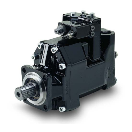
Summary of Contents for Parker Series VP1-045/-075
- Page 1 Bulletin HY30-8222-INST/UK Installation and Startup Manual Hydraulic Pumps Series VP1-045 /-075 Visit our homepage for additional support parker.com/pmde September 01 Effective: , 2016 Supersedes: August 25, 2011...
- Page 2 Load sens- 'Top' purge port if this is not possible, please contact port 'T' (BSP ing port 'LS' (BSP ") Parker Hannifin for further information. ") (BSP ") 5. A separate drain line must be installed Outlet/press. port (BSP 1") between the control drain port T and the reservoir (refer to fig.
- Page 3 If an installation according to Leif A./11-02-04 axial forces are allowed on the VP1 shaft b) or c) above, is considered, contact Parker Hannifin. VP1_to_PTO_install_09-02-12.ai Leif A. Fig. 4. VP1-045/075 shown with a bearing supported gear on an engine PTO adapter (example).
- Page 4 " (x2) (x3) 4 mm hex key 51.5 �40 BPV-VP1_unloading_valve.ai Fig. 5. BPV-VP1 unloading valve. Leif A./09-04-15 For more information also see HY30-8226-INST/UK, Installation Information Unloading Valve BPV for VP1 Parker Hannifin Pump & Motor Division Europe Trollhättan, Sweden...
-
Page 5: Start-Up Procedure
'Lower purge plug' 'Upper purge plug' Separate drain line from control port 'T' Inlet (suction) line Separate drain line from control port 'T' VP1 purging.ai Fig. 6. Purging the VP1. Leif A./06-03-15 Parker Hannifin Pump & Motor Division Europe Trollhättan, Sweden... - Page 6 Purge plug Fig. 7 Adaptor kit (P/N 379 7795) for tandem coupling. IMPORTANT Contact Parker Hannifin for additional information when considering tandem mounting a second VP1 pump. Installation information tandem coupling 1. The pump must be filled with oil and then purged before start-up.
- Page 7 25 bar but is adjustable to 35 bar. - This 25 bar setting and the installed, standard orifices usually provide an acceptable directional valve characteristic as well as system stability. For additional information, please contact Parker Hannifin. ∆p (standby pressure) adjustment Signal pressure...
- Page 8 BSP 11/4" 2" 00509035116 BSP 11/4" 21/2" 00509021916 ØA Fittings_install_GB.eps 90° adapter Leif A./020115 ØB ØA ØB Ordering no. inch BSP 11/4" 2" 00509034616 ØA Nipplar_ny.eps Leif A./05-01-21 Fig. 9. Suction fittings. Parker Hannifin Pump & Motor Division Europe Trollhättan, Sweden...
- Page 9 - Make sure you have corrected the source of the problem, not only the symptom. Parker can not be held responsible for damage to PTO, engine and gear- box caused by improper maintenance of the hydraulic system. Fig. 10. Indication hole.
- Page 10 Installation information Position notification regarding Machinery Directive 2006/42/EG: Products made by the Pump & Motor Division Europe (PMDE) of Parker Hannifin are excluded from the scope of the machinery directive following the “Cetop” Position Paper on the implementation of the Machinery Directive 2006/ 42/ EC in the Fluid Power Industry.
-
Page 11: Offer Of Sale
The user must analyze all aspects of the application, follow applicable industry standards, and follow the information concerning the product in the current product catalog and in any other materials provided from Parker or its subsidiaries or authorized distributors. -
Page 12: Installation Information
Variable displacement pump Bulletin HY30-8222-INST/UK Series VP1-045 / -075 Installation information Parker Hannifin Manufacturing Sweden AB HY30-8222-INST/UK Pump & Motor Division Europe Art. No 3780474-09 461 82 Trollhättan Sweden © Copyright 2016 Tel. +46 (0)520 40 45 00 All rights reserved...


Need help?
Do you have a question about the Series VP1-045/-075 and is the answer not in the manual?
Questions and answers