
Subscribe to Our Youtube Channel
Related Manuals for Extech Instruments PRC50


Summary of Contents for Extech Instruments PRC50
- Page 1 User Guide Multifunction Process Calibrator Model PRC50 Page 1 PRC50-EN-V2.1 11/11...
-
Page 2: Standard Accessories
Ensure that the package contains all of the accessories listed below. If items are damaged, please contact the vendor from which the product was purchased. One (1) set of Industrial Test Leads One (1) set of Standard Test Leads One (1) set of Alligator clips User's Guide Two (2) Fuses 50mA/250V and 63mA/250V Page 2 PRC50-EN-V2.1 11/11... -
Page 3: Safety Information
For the correct and safe use of the instrument, be sure to follow the cautionary notes stated in this manual whenever handling the instrument. Extech Instruments shall not be held liable for any damage resulting from use of the instrument in a manner other than prescribed in the cautionary notes. -
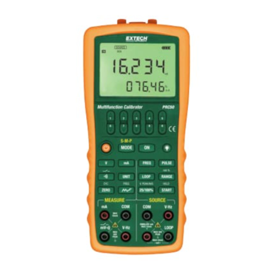
Page 4: Calibrator Description
Measurement Signals(+):DCmV、 Measurement Signals(+):DCV、FREQ Measurement Signals(+):DCmA Common (return ) (-) terminal for all measurement functions Source Signals:(-)DCmA Source Signals:(+) Simulate mA Source Signals:(+)DCmA LOOP Terminal:+24VDC Loop Power Terminal Common (return ) (-)terminal for source functions Source Signals:(+)DCV、FREQ、PULSE Page 4 PRC50-EN-V2.1 11/11... - Page 5 In frequency or pulse source, set the frequency value. In mA source function, select 25% or 100% manual step output type; In pulse number mode, frequency source, set the amplitude value; 25/100% Key Measure the average value. Page 5 PRC50-EN-V2.1 11/11...
-
Page 6: Display Screen
Start source number of pulses / DCmA auto-stepping or sweeping source function v. 24V Loop Power Supply ON w. DCmA auto-stepping or sweeping source x. Unit of measure for secondary display y. Secondary numerical display Page 6 PRC50-EN-V2.1 11/11... -
Page 7: Precautions For Safe Use Of The Instrument
In these cases, leave the instrument under the given ambient temperature for at least one hour to ensure that the instrument is free from condensation before using the instrument. Page 7 PRC50-EN-V2.1 11/11... - Page 8 Press the backlight key to switch ON the backlight; press again to switch it OFF. Battery life is shortened by backlight overuse. Notes: The backlight automatically switches OFF after 10 seconds. The time can be programmed or reset to the factory default condition, see the “Global Settings” section. Page 8 PRC50-EN-V2.1 11/11...
-
Page 9: Connecting Cables To Terminals
Step 1: Connect the black lead cable for source to the “mA-” output terminal and the red lead cable to the ‘’mA+/LOOP’’ output terminal. Step 2: Connect the other ends of the cables to the input of equipment under test while making sure the polarities are correct. Figure 6 - Sourcing DC Current Page 9 PRC50-EN-V2.1 11/11... - Page 10 Step 3: Pressing the〔ON〕key causes the indicator on the LCD to change from ‘’OFF‘’ to ‘’ON ‘’. The calibrator sources the preset DC current between the output terminals. Step 4: To turn off the output, press the〔ON〕key again. The’’ OFF ‘’icon appears on the LCD and no signals are sourced between the terminals. Page 10 PRC50-EN-V2.1 11/11...
- Page 11 The ability to use the (START) key to start mA auto-stepping and auto-sweeping mode is only available when the source function is in the ON state. Page 11 PRC50-EN-V2.1 11/11...
-
Page 12: Sourcing Frequency
Increasing the digit from 9 or decreasing it from 0 causes the digit to overflow or underflow, allowing the output value to be set without interruption. Holding down the〔 〕/〔 〕key continuously changes the digit quickly. The value won’t change if it is increased or decreased to the Maximum or Minimum value. Page 12 PRC50-EN-V2.1 11/11... - Page 13 Holding down the〔 〕/〔 〕key continuously changes the digit quickly. The value won’t change if it is increased or decreased to the Maximum or Minimum value. Step 8: To re-enter the frequency set mode, press the〔FREQ〕key. Page 13 PRC50-EN-V2.1 11/11...
- Page 14 Restarting the pulse output requires that the source function be in the ‘’ON ‘’state. 5.6 Zero-off function In any range of DC voltage or DC current pressing the (ZERO) key initializes the preset source value. In the frequency and pulse modes, the (ZERO) key function is unavailable. Page 14 PRC50-EN-V2.1 11/11...
- Page 15 “VHz” input terminal. Step 2: Connect the other end of the cable to the measuring terminals of the equipment under test while making sure the polarities are correct. Figure 9 - Measuring DC Voltage and Frequency Page 15 PRC50-EN-V2.1 11/11...
-
Page 16: Measuring Dc Voltage
Step 3: Connect the test lead cables to the terminals of the instrument under test. Step 4: Using the (RANGE) key, select a desired range from 200mV, 5V, 50V. The selected function, the measured value, and the unit of measure are shown in the upper area of the LCD. Page 16 PRC50-EN-V2.1 11/11... -
Page 17: Measuring Dc Current
Step 2: Connect the calibrator with the loop current terminals of the converter as shown in Figure 11. Figure 11 – A 24v loop power circuit supply Note: Since the function discussed above requires a significant amount of DC current (25 mA), battery operation will reduce the battery life considerably. Page 17 PRC50-EN-V2.1 11/11... -
Page 18: Measuring Frequency
The read-hold function can be used to freeze a measurement (the held measurement is shown on the upper area of the LCD). Pressing the〔HOLD〕key selects the read-hold mode and the LCD displays the “HOLD” symbol. To cancel the selection, press the〔HOLD〕key again and the “HOLD” symbol will switch OFF. Page 18 PRC50-EN-V2.1 11/11... -
Page 19: Setting The Frequency
Step 1: Use the (MODE) key to display the “FRSET” parameter at the top of the LCD (if it’s not already displayed). Step 2: Shift between 50Hz and 60Hz using the right pair of 〔 〕/〔 〕keys. Step 3: To save the setting, press the (ON) key and the LCD will show the “SAVE” symbol. Page 19 PRC50-EN-V2.1 11/11... -
Page 20: Factory Default
Step 1: Use the (MODE) key to move to the “FACry” parameter at the top of the LCD (if it’s not already displayed). Step 2: Press the (ON) key to revert to the default values as shown below: AP.OFF: 10 minutes BL.OFF: 10 seconds FRSET: 50 Hz CMSET: PCM Page 20 PRC50-EN-V2.1 11/11... - Page 21 Step 3: Replace with four (4) new AAA alkaline batteries using the instructions shown on the battery door. Replace the blown fuses with same type F1 (50mA/250V) or F2 (50mA/250V) or F3 (63mA/250V). Step 4: Reinstall and tighten the battery door, affix the protector before using the meter. Page 21 PRC50-EN-V2.1 11/11...
-
Page 22: Maintenance
Extech offers repar and calibration services for the products we sell. Extech also provides NIST certification for most products. Call the Customer Care Department for information on calibration services available for this product. Extech recommends that annual calibrations be performed to verify Page 22 PRC50-EN-V2.1 11/11... -
Page 23: Specifications
18 and 82 F to °C °C) F (28 °C to 40 °C) Maximum voltage between VΩHz terminal and COM terminal: 60 Vp-p; Maximum Input current: 55mA. Protected with a 63mA, 250V fast blow fuse Page 23 PRC50-EN-V2.1 11/11... - Page 24 F to 64 F (5 °C to 18 °C) and 82 F to F (28 °C to 40 °C) Maximum voltage between any output terminal and earth ground: 30Vpeak Maximum output current: Approximately 25mA. Copyright © 2011 Extech Instruments Corporation (a FLIR company) All rights reserved including the right of reproduction in whole or in part in any form. Page 24 PRC50-EN-V2.1 11/11...
Need help?
Do you have a question about the PRC50 and is the answer not in the manual?
Questions and answers