Table of Contents
Advertisement
Quick Links
Advertisement
Table of Contents

Subscribe to Our Youtube Channel
Related Manuals for XCOM 760

Summary of Contents for XCOM 760
- Page 1 XCOM 760 VHF Transceiver Installation and Users Manual...
- Page 2 Release 1.2 © XCOM Avionics 2004 www.xcom760.com Page 2...
-
Page 3: Table Of Contents
Operation ....................13 DUAL - MODE - ON ................. 13 Aerial Information ..................14 Wiring Diagram – Typical Installation .............. 16 XCOM VHF760 Transceiver Specifications - Subject to Change ......17 Drilling Template ..................18 Warranty Card ..................... 18 Notes......................19 Release 1.2... -
Page 4: Introduction
This radio is extremely easy to operate even when wearing flight gloves and you can even check the condition of your battery with the built in voltage monitor. Even at voltages as low as 10 volts, the XCOM 760 is capable of delivering 2 watts of carrier with full modulation. -
Page 5: Manual Release Information
• Optional MARS / CAP capability (special order) XCOM Avionics reserves the right to update this manual as product enhancements are made throughout the life of this product. The actual release number of this manual is printed on the bottom of the pages for easy reference and the latest version can always be downloadable from the XCOM web site. -
Page 6: Contents
- select warranty registration Description The XCOM VHF 760 Transceiver has a 2 ¼ inch (57mm) face for fitting in a normal aircraft small instrument hole. The case is 129mm long, 61mm wide and 61mm high. The unit is secured to the aircraft dashboard by 4 screws and is self supporting and requires no additional supports, trays or brackets. -
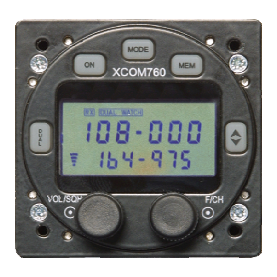
Page 7: Front Panel Controls And Switches
To activate the KHz, press the control in once, rotating left decreases the KHz whilst rotating right increases. After 3 seconds of inactivity the control will revert back to KHz Release 1.2 © XCOM Avionics 2004 www.xcom760.com Page 7... -
Page 8: Lcd Display
Top Line Displays the active channel in the larger text Bottom line Displays the standby channel, memory number and other status text. Bar Graph Received volume and squelch levels as well as intercom volume and squelch levels. Release 1.2 © XCOM Avionics 2004 www.xcom760.com Page 8... -
Page 9: Xcom Installation
XCOM Installation The XCOM 760 VHF Transceiver installation is straight forward and requires no special skills, the wiring harness does require someone with a reasonable knowledge of wiring and the proper equipment for the installation, it’s our recommendation to purchase the pre-made wiring harness or have a local avionics shop do the job for you. -
Page 10: Operating Your Xcom Transceiver
Operating your XCOM Transceiver On - To switch the unit on simply depress the ON button for one second. The transceiver will switch on. To switch off hold the button in for 2 seconds, the transceiver will switch OFF. The transceiver will start up in whatever mode it was left in, e.g. -
Page 11: Dual
1 second will revert back to main screen. When in MODE screens, hitting the button will either enter and return or just return back to the main screen. Release 1.2 © XCOM Avionics 2004 www.xcom760.com Page 11... -
Page 12: Memory Programming
The above programming and erasing feature can also be done via the RS 232 port, using the free XCOM760 utility from the xcom760.com website. Release 1.2 © XCOM Avionics 2004 www.xcom760.com Page 12... -
Page 13: Setup Options
This sets the HIGH point trip for the battery alert, Rotate the F/CH control to set the upper limit. The default is 15 Release 1.2 © XCOM Avionics 2004 www.xcom760.com Page 13... -
Page 14: Aerial Information
Aerial Information The XCOM 760 Transceiver is a state-of-the-art product and requires a quality and matching aerial to provide owners with the best possible performance, clarity and range. Some of the most important considerations are the location of the aerial and the proper installation and cabling to the radio. - Page 15 Release 1.2 © XCOM Avionics 2004 www.xcom760.com Page 15...
-
Page 16: Wiring Diagram - Typical Installation
Wiring Diagram – Typical Installation XCOM VHF76 0 TRANSCEIVER W IRING DIAGRAM Ver sion 1 - Issu ed Ju ly 20 0 4 Copyrig ht X COM Av ionics w w w.x com7 6 0.com All wires 22 AWG except power and ground... -
Page 17: Xcom Vhf760 Transceiver Specifications - Subject To Change
• Note: Transceiver was designed to these specifications and meets and complies with these, but has not yet been submitted for official TSO testing. • 118.000 to 136.975 MHz, 760 channels transmit and receive (AM) • 137 to 163 MHz general coverage receive including NOAA weather channels. -
Page 18: Drilling Template
ASAP to the address above, please don’t return to your dealer. The warranty details may also be completed electronically through the web site http://www.xcom760.com We look forward to hearing your experiences with the XCOM range, should you have any questions on the installation or performance of this product please email tech@xcom760.com for a prompt reply. -
Page 19: Notes
Notes Please retain this manual for future reference Release 1.2 © XCOM Avionics 2004 www.xcom760.com Page 19... - Page 20 Release 1.2 © XCOM Avionics 2004 www.xcom760.com Page 20...
Need help?
Do you have a question about the 760 and is the answer not in the manual?
Questions and answers