Table of Contents

Subscribe to Our Youtube Channel
Related Manuals for XCOM 760

Summary of Contents for XCOM 760
- Page 1 XCOM 760 VHF Transceiver Hardware Revision 1.10 Software Rev. 1.20 Build 46 Installation and Users Manual XCOM Avionics Factory 4, No. 24 Leda Drive. Leda Business Park Burleigh Heads, Queensland Australia 4226. Phone +61 7 5568 7770 +61 7 5568 7772...
- Page 2 Release 1.7 © XCOM Avionics 2005 www.xcom760.com Page 2...
-
Page 3: Table Of Contents
Setup Options .................... 14 Introduction ..................14 Operation ..................... 14 Antenna Information ................... 16 Wiring Diagram – Typical Installation............. 18 XCOM VHF Transceiver Specifications - Subject to Change ........ 19 Drilling Template ..................24 Notes ......................25 Warranty Card.................... 26 Release 1.7 ©... -
Page 4: Introduction
This radio is extremely easy to operate, even when wearing flight gloves, and you can even check the condition of your battery with the built in voltage monitor. Even at voltages as low as 10 volts, the XCOM 760 is capable of delivering 2 watts of carrier with full modulation. -
Page 5: Manual Release Information
Optional MARS / CAP capability (special order to be introduced during 2005/6 subject to FCC approvals) XCOM Avionics reserves the right to update this manual as product enhancements are made throughout the life of this product. The actual release number of this manual is printed on the bottom of the pages for easy reference and the latest version can always be downloaded from the XCOM web site. -
Page 6: Package Contents
(select warranty registration). Description The XCOM VHF 760 Transceiver has a 2.25” (57mm) face for fitting in a normal aircraft small instrument hole. The case is 5.1” (129mm) long, 2.4” (61mm) wide and 2.4” (61mm) high. The unit is secured to the aircraft dashboard by 4 screws and is self supporting, requiring no additional supports, trays or brackets. -
Page 7: Front Panel Controls And Switches
See AdjAct section on page 14 for additional information. Emergency Frequency – Press both buttons together and you will automatically activate the emergency frequency 121.5 – press the flip/flop to exit. Release 1.7 © XCOM Avionics 2005 www.xcom760.com Page 7... -
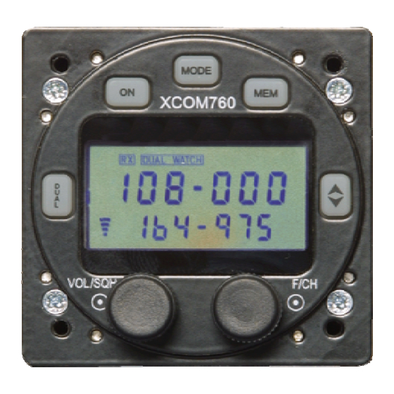
Page 8: Lcd Display
MEM Indicates functions of the memory modes. Please see below for additional explanation. Middle Line Displays the active frequency Bottom line Displays the standby frequency and other status text. Release 1.7 © XCOM Avionics 2005 www.xcom760.com Page 8... -
Page 9: Xcom Installation
It is our recommendation that installers purchase the factory manufactured wiring harness or that owners have a local avionics repair or maintenance facility install the XCOM 760 for you. When positioning the radio, ensure that the controls are within easy reach of the pilot and in a suitable viewing angle when the pilot is sitting and secured in the pilot’s seat. -
Page 10: Antennas
RF is grounded, which will prevent RF feedback from entering the radio and causing squeals or other noise when transmitting. Operating your XCOM Transceiver On - To switch the unit on simply depress the ON button for one second. To switch the unit off, hold the button in for 2 seconds. -
Page 11: Mem
If a signal is received on the active frequency, the transceiver automatically switches to that frequency. When the signal ceases, the unit returns to the standby frequency and continues scanning the active. Release 1.7 © XCOM Avionics 2005 www.xcom760.com Page 11... -
Page 12: Flip Flop Button ( )
Memory Programming Introduction - The XCOM 760 has 99 user programmable memory channels, stored in non-volatile memory. The memory channels can be programmed via the keypad or via the RS232 data link (using the serial port and Windows based software). -
Page 13: Clearing Memories
To exit the memory programming screen, press Memory Scanning Introduction - The XCOM 760 has 99 user programmable memory channels, stored in non-volatile memory. These channels can be scanned sequentially. If a signal is received in a channel, the scanning is paused. Scanning resumes 3 seconds after the signal is lost. -
Page 14: Setup Options
Introduction These advanced options should be modified only by experienced users. Modification of these options affects the way in which the XCOM operates, the features available, and may affect the performance of the unit. These options should not be modified in flight. - Page 15 Rotate the F/CH control to set the value. Ptt2 This setting determines the mode of operation of the copilot PTT Option switch. The default is on. Release 1.7 © XCOM Avionics 2005 www.xcom760.com Page 15...
-
Page 16: Antenna Information
Rotate the F/CH control to toggle the setting on or off. Antenna Information The XCOM 760 Transceiver is a state-of-the-art product and requires a quality, matched antenna to provide the best possible performance, clarity and range. Some of the most important considerations are the location of the antenna, proper installation and high quality cable and connectors. - Page 17 (silicone) a thin piece of aluminum sheet inside the structure to provide an adequate ground plane. Ground plane independent antennas are suitable for use with the XCOM. However, in our experience, a fully grounded antenna with a large ground plane provides superior performance.
-
Page 18: Wiring Diagram - Typical Installation
Wiring Diagram – Typical Installation XCOM VHF760 TRANSCEIVER WIRING DIAGRAM Version 3 - Issued August 2005 Copyright XCOM Avionics www.xcomavionics.com All wires 22 AWG except power and ground Pins Wire 18 AWG 9 10 +13.8 V 3A Fuse must be installed... -
Page 19: Xcom Vhf Transceiver Specifications - Subject To Change
TSO testing • 118.000 to 136.975 MHz, 760 channels transmit and receive (AM) receiver sensitivity AM (118 – 136.975 MHz.): not less than 12 db SINAD for 1.5 uv (30% AM at 1 kHz. - Page 20 Dear Mr. Leimer: The Federal Aviation Administration's ATC Spectrum Engineering Services, has reviewed the type Acceptance Certification request from X-Air Australia for the XCOM 760VHF transceiver ID number QLDXCOMVHF. The technical data for this equipment is consistent with the spectrum requirements and we have no objections to certification of this device.
- Page 21 Notes: VHF Aircraft Transceiver Frequency Output Frequency Emission Grant Notes FCC Rule Parts Range (MHZ) Watts Tolerance Designator 118.0 – 136.975 30.0 PM 6K00A3E Power listed is at the antenna terminal Release 1.7 © XCOM Avionics 2005 www.xcom760.com Page 21...
- Page 22 Release 1.6 © XCOM Avionics 2005 www.xcom760.com Page 22...
- Page 23 Report date: 2 April 2004 COMPLIANCE STATEMENT / ATTESTATION Testing of the Xcom 760 VHF Aircraft Transceiver complies with the Code of Federal Regulations (CFR) 47 Part 87 - Aviation Services and (CFR) 47 Part 15 -Radio Frequency Devices. This report describes the tests and measurements performed for the purpose of determining compliance with the specification with the following conditions: The client selected the test sample.
-
Page 24: Drilling Template
XCOM’s installation. If you have this diagram in a small booklet then it is not to scale ! Standard Cutout for XCOM Radio # 27 Drill 9/64” Drill 3.5 mm Drill 2.3125” Dia Release 1.6... -
Page 25: Notes
Notes Release 1.6 © XCOM Avionics 2005 www.xcom760.com Page 25... -
Page 26: Warranty Card
We look forward to hearing of your experiences with the XCOM range. Should you have any questions regarding the installation, operation or performance of this product, please visit our web site or email tech@xcom760.com for a prompt reply.
Need help?
Do you have a question about the 760 and is the answer not in the manual?
Questions and answers