Cisco Firepower 4100 Series Hardware Installation Manual
Hide thumbs
Also See for Firepower 4100 Series:
- User manual ,
- Command reference manual (421 pages) ,
- Hardware installation manual (78 pages)
Table of Contents
Advertisement
Advertisement
Chapters
Table of Contents

Related Manuals for Cisco Firepower 4100 Series


Summary of Contents for Cisco Firepower 4100 Series
- Page 1 Cisco Firepower 4100 Series Hardware Installation Guide First Published: 2016-03-31 Last Modified: 2017-04-27 Americas Headquarters Cisco Systems, Inc. 170 West Tasman Drive San Jose, CA 95134-1706 http://www.cisco.com Tel: 408 526-4000 800 553-NETS (6387) Fax: 408 527-0883...
- Page 2 Cisco and the Cisco logo are trademarks or registered trademarks of Cisco and/or its affiliates in the U.S. and other countries. To view a list of Cisco trademarks, go to this URL: www.cisco.com/go/trademarks . Third-party trademarks mentioned are the property of their respective owners. The use of the word partner does not imply a partnership relationship between Cisco and any other company.
- Page 3 Safety Recommendations Maintain Safety with Electricity Prevent Electrostatic Discharge Damage Site Environment Power Supply Considerations Equipment Rack Configuration Considerations Mount and Connect C H A P T E R 3 Rack-Mount the Chassis Cisco Firepower 4100 Series Hardware Installation Guide...
-
Page 4: Table Of Contents
Remove and Replace the Fan Module Remove and Replace the SSD Remove and Replace the Power Supply Module Connect the DC Power Supply Module Secure the Power Cord on the AC Power Supply Module Cisco Firepower 4100 Series Hardware Installation Guide... - Page 5 About the Cisco Firepower 4100 Security Appliance The Cisco Firepower 4100 security appliance is a standalone modular security services platform with a one RU form factor. It is capable of running multiple security services simultaneously and so is targeted at the data center as a multi-service platform.
-
Page 6: Overview
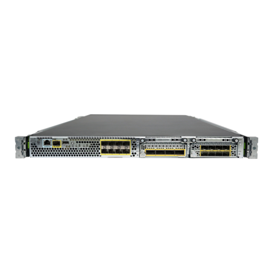
(cold aisle) and the power supplies, power entry, and fans are in the rear. Air flow is from front to rear (cold aisle to hot aisle). The following figure shows the Firepower 4100 series security appliance. Figure 1: Firepower 4100 Series Security Appliance... - Page 7 The Firepower 4150 has a dual 22-core processor, dual redundant AC power supply modules, one 400-GB SSD in slot 1, and 256-GB of DDR4 RAM. The second SSD bay is reserved for the MSP SSD. Cisco Firepower 4100 Series Hardware Installation Guide...
-
Page 8: Deployment Options
• In newer spine/leaf data center designs, deployment as a leaf that exclusively offers security functions Package Contents The following figure shows the package contents for the Firepower 4100 series security appliance. Note that the contents are subject to change and your exact contents might contain additional or fewer items. -
Page 9: Serial Number Location
Welcome to the Cisco Firepower 4100 Serial Number Location The serial number for the Firepower 4100 series chassis is located on the pull-out label card on the front panel. Figure 3: Serial Number on 4100 Chassis Cisco Firepower 4100 Series Hardware Installation Guide... -
Page 10: Front Panel
Overview Front Panel Front Panel The following figure shows the front panel of the Firepower 4100 series security appliance. Figure 4: Firepower 4100 Series Front Panel RJ-45 console port Gigabit Ethernet management port Type A USB port Eight fixed SFP+ (1G/10G) ports are... -
Page 11: Front Panel
Overview Front Panel LEDs Front Panel LEDs The following figure and table describe the Firepower 4100 series security appliance front panel LEDs. Figure 5: Front Panel LEDs Management Health (SYS) • Unlit – No connection or port is • Solid Green – Normal. -
Page 12: Rear Panel
• Solid green – Link up. • Blinking green – Network activity. Rear Panel The following figure shows the rear panel of the Firepower 4100 series security appliance. Figure 6: Firepower 4100 Series Rear Panel Power on/off switch Power supply module 1... - Page 13 LEDs, and the port configurations for the hardware bypass network modules. • See Remove and Replace the Network Module, on page 59 for the procedure for removing and replacing network modules. Cisco Firepower 4100 Series Hardware Installation Guide...
-
Page 14: Network Modules
Network activity LEDs • Unlit – No connection or port is not in use. • Solid amber – No link or network failure. • Solid green – Link up. • Blinking green – Network activity. Cisco Firepower 4100 Series Hardware Installation Guide... -
Page 15: Nonhardware (Ftw) Bypass Network Modules
LEDs, and the port configurations for the hardware bypass network modules. • See Remove and Replace the Network Module, on page 59 for the procedure for removing and replacing network modules. Cisco Firepower 4100 Series Hardware Installation Guide... - Page 16 If you have a inline interface set with a mix of FTW-capable and non FTW-capable interfaces, you cannot Note enable hardware bypass on this inline interface set. You can only enable hardware bypass on an inline interface set if all the pairs in the inline set are valid FTW pairs. Cisco Firepower 4100 Series Hardware Installation Guide...
-
Page 17: Hardware Bypass (Ftw) Network Modules
Ports 7 and 8 are paired together to to form a hardware bypass pair. form a hardware bypass pair. LED LED B3 applies to this paired B4 applies to this paired port. port. Cisco Firepower 4100 Series Hardware Installation Guide... - Page 18 • Solid green – In Standby form a hardware bypass pair. mode. • Blinking amber – Port is in hardware bypass mode, failure event. • Solid amber – Port is in hardware bypass mode, forced. Cisco Firepower 4100 Series Hardware Installation Guide...
- Page 19 • Solid amber – No connection, or port is not in use, or no link or network failure. • Solid green – Link up, no network activity. • Blinking green – Network activity. Cisco Firepower 4100 Series Hardware Installation Guide...
- Page 20 160 (FDDI) 110 m Cable and operating distance 62.5 200(OM1) 137 m 250 m 500 (OM2) 275 m 2000 (OM3) 500 m Table 2: 10G SR Network Module (FPR-NM-6X10SR-F) Operating Mode Typical Maximum Cisco Firepower 4100 Series Hardware Installation Guide...
- Page 21 LEDs, and the port configurations for the non-hardware bypass network modules. • See Remove and Replace the Network Module, on page 59 for the procedure for removing and replacing network modules. Cisco Firepower 4100 Series Hardware Installation Guide...
- Page 22 The power supplies can supply up to 950W power across the input voltage range. The load is shared when both power supply modules are plugged in and running at the same time. The power supply modules are hot-swappable. Cisco Firepower 4100 Series Hardware Installation Guide...
-
Page 23: Power Supply Modules
Amber FAIL LED Green OK LED The following table describes the power module supply LEDs. Table 6: Power Supply Module LEDs Amber LED (Fail Status) Green LED (OK Status) No power to all power supplies Cisco Firepower 4100 Series Hardware Installation Guide... - Page 24 Remove and Replace the Fan Module, on page 62 for the procedure for removing and replacing the fan module. The following figure shows the location of the fan LED. Figure 13: Fan LED Cisco Firepower 4100 Series Hardware Installation Guide...
-
Page 25: Fan Modules
Bail clasp Receive optical bore Transmit optical bore Although non-Cisco SFPs are allowed, we do not recommend using them because they have not been Caution tested and validated by Cisco. Cisco TAC may refuse support for any interoperability problems that result from using an untested third-party SFP transceiver. -
Page 26: Supported Sfp/Sfp+ Transceivers
For some earlier production Firepower 4100 series chassis, you may experience difficulty using the Caution GLC-TE SFP on the management port or fixed ports. Contact Cisco TAC for support if you encounter problems with the GLC-TE SFP. The following table lists the Cisco supported transceivers. - Page 27 40GE-LR4 QSFP-40GE-LR4 40GE-LR4-S QSFP-40GE-LR4-S 40G-LR4L WSP-Q40GLR4L 40G-CU, 1M, 3M, 5M QSFP-H40G-CU 40G-4X10G-CU, 1M, 3M, 5M QSFP-4SFP10G-CU 40G-CU-A, 7M, 10M QSFP-H40G-ACU 40G-4X10G-CU-A, 7M, 10M QSFP-4X10G-AC 40G-AOC, 1M, 2M, 3M, 5M, 7M, 10M, 15M QSFP-H40G-AOC Cisco Firepower 4100 Series Hardware Installation Guide...
- Page 28 AC power cord (Italy) See Figure 18 below. CAB-9K10A-AR 250V IRAM 2073 IEC 60320-C15 AC power cord (Argentina) See Figure 19 below. CAB-9K10A-SW 250V SEV 1011 IEC 60320-C15 AC power cord (Switzerland) See Figure 20 below. Cisco Firepower 4100 Series Hardware Installation Guide...
-
Page 29: Power Cord Specifications
Telepresence G2A power cord (Brazil) See Figure 27 below. CAB-9K10A-TWN 125V CNS10917-2 IEC 60320-C15 AC power cord (Taiwan) See Figure 28 below. CAB-250V-10A-IS 250V SI-32 IEC 60320-C13 AC power cord (Israel) See Figure 29 below. Cisco Firepower 4100 Series Hardware Installation Guide... - Page 30 The following figures show the cord, connector, and plug for each country listed in the table above. Figure 15: CAB-AC-EUR (Europe) Plug: CEE 7/7 Cord set rating: 10A, 250V Connector: IEC 60320-C15 Figure 16: CAB-TA-NA (North America) Plug: NEMA5-15P Cord set rating: 12A, 125V Cisco Firepower 4100 Series Hardware Installation Guide...
- Page 31 Connector: IEC 60320-C15 Figure 17: CAB-9K10A-AU (Australia) Plug: A.S. 3112-2000 Cord set rating: 10A, 250V Connector: IEC 60320-C15 Figure 18: CAB-9K10A-IT (Italy) Plug: CEI 23-16/VII Cord set rating: 10A, 250V Connector: IEC 60320-C15 Cisco Firepower 4100 Series Hardware Installation Guide...
- Page 32 Power Cord Specifications Figure 19: CAB-9K10A-AR (Argentina) Plug: IRAM 2073 Cord set rating: 10A, 250V Connector: IEC 60320-C15 Figure 20: CAB-9K10A-SW (Switzerland) Plug: SEV 1011 Cord set rating: 10A, 250V Connector: IEC 60320-C15 Cisco Firepower 4100 Series Hardware Installation Guide...
- Page 33 Power Cord Specifications Figure 21: CP-PWR-CORD-UK (United Kingdom) Plug: BS1363A/SS145 Cord set rating: 10A, 250V Connector: IEC 60320-C13 Figure 22: CAB-TA-JP (Japan) Plug: NEMA5-15P/JIS 8303 Cord set rating: 12A, 125V Connector: IEC 60320-C15 Cisco Firepower 4100 Series Hardware Installation Guide...
- Page 34 Power Cord Specifications Figure 23: CAB-L620P-C13-JPN (Japan) Plug: NEMA L6-20P Cord set rating: 15A, 250V Connector: IEC 60320-C13 Figure 24: CAB-9K10A-SA (South Africa) Plug: SABS 164 Cord set rating: 10A, 250V Connector: IEC 60320-C15 Cisco Firepower 4100 Series Hardware Installation Guide...
- Page 35 Power Cord Specifications Figure 25: CAB-9K10A-CH (China) Plug: CCC GB2099.1, GB1002 Cord set rating: 10A, 250V Connector: IEC 60320-C15 Figure 26: CAB-250V-10A-ID (India) Plug: IS 6538-1971 Cord set rating: 10A, 250V Connector: IEC 60320-C13 Cisco Firepower 4100 Series Hardware Installation Guide...
- Page 36 Overview Power Cord Specifications Figure 27: PWR-CORD-G2A-BZ (Brazil) Plug: NBR 14136 Cord set rating: 10A, 250V Connector: IEC 60320-C13 Figure 28: CAB-9K10A-TWN (Taiwan) Plug: CNS10917-2 Cord set rating: 10A, 125V Connector: IEC 60320-C15 Cisco Firepower 4100 Series Hardware Installation Guide...
- Page 37 Overview Power Cord Specifications Figure 29: CAB-250V-10A-IS (Israel) Plug: SI-32 Cord set rating: 10A, 250V Connector: IEC 60320-C13 Figure 30: UNITY-PWR-DEN (Denmark) Plug: IEC 60884-1 Cord set rating: 10A, 250V Connector: IEC 60320-C13 Cisco Firepower 4100 Series Hardware Installation Guide...
-
Page 38: Hardware Specifications
Figure 31: ATA187PWRCORD-SAUD (Saudi Arabia) Plug: BS1363A/SS145 Cord set rating: 10A, 250V Connector: IEC 60320-C13 Hardware Specifications The following table contains hardware specifications for the Firepower 4100 series security appliance. Physical Form factor 1 RU, fits standard 19-in (48.3-cm) square-hole rack Rack mountable... -
Page 39: Hardware Specifications
• Operating: 10,000 ft maximum (3048 m) • Nonoperating: 40,000 ft maximum (12,192 m) Acoustic Noise Sound Pressure: • 61 dBA (typical) • 78 dBA (maximum) Sound Power • 72 dBA (typical) • 88 dBA (maximum) Cisco Firepower 4100 Series Hardware Installation Guide... - Page 40 • Long term: 0⁰ to 45⁰C up to 6000 ft (1829 m) • Long term: 0⁰ to 35⁰C up to 6000-13,000 ft (1829-3964 m) • Short term: -5⁰ to 55⁰C up to 6000 ft (1829 m) Operating altitude: 0 to 13,000 ft (3962 m) Cisco Firepower 4100 Series Hardware Installation Guide...
-
Page 41: Chapter
(EMI) that might disrupt other equipment; and they direct the flow of cooling air through the chassis. Do not operate the system unless all cards, faceplates, front covers, and rear covers are in place. Cisco Firepower 4100 Series Hardware Installation Guide... -
Page 42: Installation Notes And Warnings
Statement 94—Wrist Strap Warning During this procedure, wear grounding wrist straps to avoid ESD damage to the card. Do not directly touch the backplane with your hand or any metal tool, or you could shock yourself. Cisco Firepower 4100 Series Hardware Installation Guide... -
Page 43: Safety Recommendations
• Do not wear loose clothing or jewelry, such as earrings, bracelets, or chains that could get caught in the chassis. • Wear safety glasses if you are working under any conditions that might be hazardous to your eyes. Cisco Firepower 4100 Series Hardware Installation Guide... -
Page 44: Maintain Safety With Electricity
If no wrist strap is available, ground yourself by touching the metal part of the chassis. For safety, periodically check the resistance value of the antistatic strap, which should be between one and 10 megohms. Cisco Firepower 4100 Series Hardware Installation Guide... -
Page 45: Site Environment
• Baffles can help to isolate exhaust air from intake air, which also helps to draw cooling air through the chassis. The best placement of the baffles depends on the airflow patterns in the rack. Experiment with different arrangements to position the baffles effectively. Cisco Firepower 4100 Series Hardware Installation Guide... -
Page 46: Equipment Rack Configuration Considerations
Prepare for Installation Equipment Rack Configuration Considerations Cisco Firepower 4100 Series Hardware Installation Guide... -
Page 47: Chapter
C H A P T E R Mount and Connect This chapter describes how to rack-mount the Cisco Firepower 4100 security appliance, how to ground it, and how to connect the cords and cables. It contains the following sections: •... -
Page 48: Mount And Connect
Slide rail assemblies work with four-post racks and cabinets with square slots, round 7.1mm holes and 10-32 threaded holes on the rack post front. The slide rail works with front to back spacing of rack posts from 24 to 36 inches. Cisco Firepower 4100 Series Hardware Installation Guide... - Page 49 Set the keyed slots over the pegs, and then slide the rail toward the front to lock it in place on the pegs. The rear key slot has a metal clip that locks over the peg. d) Secure the inner rail to the side of the chassis using one M3X6mm screw. Cisco Firepower 4100 Series Hardware Installation Guide...
- Page 50 On the outside of the assembly, push the green arrow button toward the rear to open the securing plate. Cisco Firepower 4100 Series Hardware Installation Guide...
- Page 51 Align the rear of the inner rails that are attached to the chassis sides with the front ends of the empty slide rails on the rack. b) Push the inner rails into the slide rails on the rack until they stop at the internal stops. Cisco Firepower 4100 Series Hardware Installation Guide...
- Page 52 Use the captive screws on the front of the mounting brackets to fully secure the chassis to the rack. What to Do Next Continue with Connect Cables, Turn on Power, and Verify Connectivity, on page Cisco Firepower 4100 Series Hardware Installation Guide...
-
Page 53: Ground The Chassis
Make sure that the lug and cable do not interfere with other equipment. Step 7 Prepare the other end of the grounding cable and connect it to an appropriate grounding point in your site to ensure adequate earth ground. Cisco Firepower 4100 Series Hardware Installation Guide... -
Page 54: Install The Fips Opacity Shield
Note number on a label and attach it to the chassis where it can be retrieved or viewed easily before you install the FIPS opacity shield. You need the serial number when you call Cisco TAC. Before You Begin You need the following to install the FIPS opacity shield: •... - Page 55 Rack-Mount the Chassis, on page Figure 36: Attach the Slide Rail Locking Bracket to the Side of the Chassis Chassis Slide rail locking bracket 8-32 x .375" countersink Phillips head screws (3 per side) Cisco Firepower 4100 Series Hardware Installation Guide...
- Page 56 If the attached cables do not have enough slack to route them through the cable mounting brackets (as shown below), power down the appliance, remove the cables, route the cables through the cable mounting brackets, reattach the cables, and continue with step 7 below. Cisco Firepower 4100 Series Hardware Installation Guide...
- Page 57 Mount and Connect Install the FIPS Opacity Shield Step 6 Route the cables through the openings in the cable management brackets. Figure 38: Route the Cables Through the Cable Management Brackets Cisco Firepower 4100 Series Hardware Installation Guide...
- Page 58 During this time, the power LED on the front panel blinks green. Do not remove the power cable until the power LED is completely off. Step 12 See the quick start guide for your operating software for further configuration information: Cisco Firepower 4100 Series Hardware Installation Guide...
-
Page 59: Connect Cables, Turn On Power, And Verify Connectivity
Warning Statement 1055—Class I and Class 1M Laser Class I (CDRH) and Class 1M (IEC) laser products. After rack mounting the Firepower 4100 series security appliance, follow these steps to connect cables, turn on power, and verify connectivity. Step 1 Connect the console port. - Page 60 Warning to the transceiver, the chassis, or both. Although non-Cisco SFPs are allowed, we do not recommend using them because they have not been tested Caution and validated by Cisco. Cisco TAC may refuse support for any interoperability problems that result from using an untested third-party SFP transceiver.
- Page 61 Mount and Connect Connect Cables, Turn on Power, and Verify Connectivity • Cisco Firepower Threat Defense for Firepower 4100 Quick Start Guide Cisco Firepower 4100 Series Hardware Installation Guide...
- Page 62 Mount and Connect Connect Cables, Turn on Power, and Verify Connectivity Cisco Firepower 4100 Series Hardware Installation Guide...
-
Page 63: Maintenance And Upgrades
(EMI) that might disrupt other equipment; and they direct the flow of cooling air through the chassis. Do not operate the system unless all cards, faceplates, front covers, and rear covers are in place. Cisco Firepower 4100 Series Hardware Installation Guide... - Page 64 Although the hardware supports removing and replacing the network module while the system is running, the software does not currently support hot swapping. You must power up the chassis to remove and replace network modules. Cisco Firepower 4100 Series Hardware Installation Guide...
- Page 65 Power up the chassis so that the new network module is recognized. What to Do Next Follow the procedures in the FXOS Configuration Guide to connect to the network module and make sure that it has been discovered correctly by the Firepower 4100. Cisco Firepower 4100 Series Hardware Installation Guide...
-
Page 66: Remove And Replace The Fan Module
You can remove and replace fan modules while the system is running. The air flow moves from front to back. If you remove a fan or a fan fails, the other fans operate at full speed, which can be noisy. Cisco Firepower 4100 Series Hardware Installation Guide... - Page 67 Step 6 Verify that the fan is operational by checking the fan module LED. See Front Panel LEDs, on page 7 for a description of the fan LEDs. Cisco Firepower 4100 Series Hardware Installation Guide...
-
Page 68: Remove And Replace The Ssd
It supports the Advanced Malware Protection software feature. The MSP is supported beginning in FXOS 2.0.1. It is used as both storage and as the Malware application repository. RAID is not supported. Cisco Firepower 4100 Series Hardware Installation Guide... -
Page 69: Remove And Replace The Power Supply Module
Verify that the SSD is operational by checking the SSD LED. See Front Panel LEDs, on page 7 for a description of the fan LEDs. Remove and Replace the Power Supply Module Take note of the following warnings: Cisco Firepower 4100 Series Hardware Installation Guide... - Page 70 Ultimate disposal of this product should be handled according to all national laws and regulations. Warning Statement 1045—Short-circuit Protection This product requires short-circuit (overcurrent) protection to be provided as part of the building installation. Install only in accordance with national and local wiring regulations. Cisco Firepower 4100 Series Hardware Installation Guide...
- Page 71 No user-serviceable parts inside. Do not open. Warning Statement 1077—Do Not Operate Unit Without Covers The covers are an integral part of the safety design of the product. Do not operate the unit without the covers installed. Cisco Firepower 4100 Series Hardware Installation Guide...
- Page 72 Press the latch found on the lower right of the power supply to disengage the power supply. Step 3 Place your other hand under the power supply module to support it while you slide it out of the chassis. Figure 44: Remove the Power Supply Module Cisco Firepower 4100 Series Hardware Installation Guide...
-
Page 73: Connect The Dc Power Supply Module
Statement 1022—Disconnect Device Warning A readily accessible two-poled disconnect device must be incorporated in the fixed wiring. Statement 1025—Use Copper Conductors Only Warning Use copper conductors only. Cisco Firepower 4100 Series Hardware Installation Guide... - Page 74 Be sure uninsulated conductors are not accessible when cover is in place. Each DC input power cable is terminated at the PDU by a cable lug, as shown in the following figure. Cisco Firepower 4100 Series Hardware Installation Guide...
- Page 75 All DC input power cables for the chassis should be 10gauge wire and cable lengths should match within 10 percent of deviation. • Tools needed: ◦ Phillips head screwdriver ◦ 10-mm wrench or socket Cisco Firepower 4100 Series Hardware Installation Guide...
- Page 76 Step 4 To remove the plastic cover from the terminal block, insert a flat screw driver on the side of the plastic cover and pry it off. Figure 46: Remove the Plastic Cover Cisco Firepower 4100 Series Hardware Installation Guide...
- Page 77 For easier cable management, insert the negative lead cable first. Replace the grounding lug with the cable in the following order—wire terminal, then the screw with the captive washer. Figure 48: Insert the Cables Cisco Firepower 4100 Series Hardware Installation Guide...
- Page 78 Tighten the M5 screw with the captive washer to the recommended torque of 5 in-lbs for the positive stud and wire. Secure the wires coming in from the terminal block so that they cannot be disturbed by casual contact. Figure 49: Tighten the M5 Screws Cisco Firepower 4100 Series Hardware Installation Guide...
-
Page 79: Secure The Power Cord On The Ac Power Supply Module
The black tie wrap is used with the Flextronics power supply module and the off-white tie wrap is used with the Artesyn power supply module. The black clamp works with both. See the figures below. Take note of the following warnings: Cisco Firepower 4100 Series Hardware Installation Guide... - Page 80 (see the following figures). b) Plug the snapping portion of the tie wrap into the hexagonal hole. c) With the clamp side facing up, push the tie wrap in until it is fully engaged. Cisco Firepower 4100 Series Hardware Installation Guide...
- Page 81 Figure 52: Flextronics Power Supply Module Flextronics tie wrap Hexagonal hole Figure 53: Artesyn Power Supply Module Artesyn tie wrap Hexagonal hole Cisco Firepower 4100 Series Hardware Installation Guide...
- Page 82 If you need to remove the power cord, push the release tab on the clamp to force the annular clamp teeth to disengage and the clamp opens up. You can then remove the clamp from the power cord. Cisco Firepower 4100 Series Hardware Installation Guide...
Need help?
Do you have a question about the Firepower 4100 Series and is the answer not in the manual?
Questions and answers