
Related Manuals for DeVilbiss iFill 535D


Summary of Contents for DeVilbiss iFill 535D
- Page 1 ill ® ilbiss i ersonal xygen tation erVice anual Danger – no smoking Model 535D Model 535I -Federal (U.S.A.) law restricts this device to sale by or on the order of a physician. CAUTION...
-
Page 2: Table Of Contents
DeVilbiss iFill Personal Oxygen Station . . . . . . . . . . . . . . . . . . -
Page 3: General Information
Because of the stand-alone feature, iFill can be used in conjunction with any concentrator . – DeVilbiss reserves the right to alter or change the design of the DeVilbiss iFill Personal Oxygen Station series. Hence, slight NOTE differences in construction or components may exist between the unit in hand and what is described in this manual. - Page 4 – Do not connect to an electrical outlet controlled by a wall switch. No other appliances should be plugged into the wall outlet. NOTE – The plug on the 535D DeVilbiss iFill Personal Oxygen Station has one blade wider than the other. To reduce the risk of NOTE electric shock, this plug is intended to fit in a wall outlet only one way.
-
Page 5: Unpacking And Setup
. station may occur. After removing the oxygen station from the carton, examine There are three (3) methods to safely transport the DeVilbiss it for any external damage . If shipping damage has iFill Personal Oxygen Station: occurred, contact the DeVilbiss Customer Service Pull or push the unit on its casters using the front handle . -
Page 6: Operating Instructions
Otherwise, severe injury and/or damage may operating instructions occur. Connecting The iFill Oxygen Cylinder To The DeVilbiss iFill Use extreme care when handling and filling an oxygen Personal Oxygen Station cylinder. Full oxygen cylin ders are under pressure and can Danger become a projectile if dropped or mishandled. -
Page 7: Maintenance
M A I N T E N A N C E aLert sYstem The DeVilbiss iFill Personal Oxygen Station alert system will detect unit component failure . This system is comprised of both visible and audible alerts which signal the patient if a malfunction should occur . -
Page 8: Troubleshooting
. It enters the 1st stage cylinder through an inlet check valve and is pressurized to approximately 200 to 500 psi . This The DeVilbiss iFill Personal Oxygen Station uses a dual- pressure will vary based on what part of the filling cycle it is on. -
Page 9: Do First
T R O U B L E S H O O T I N G • Small Magnet: Placed on the intensifier center drive –After completing any repairs, ensure hour meter on NOTE section to visually indicate intensifier operation. the right cover is connected to the DC wire harness and the control panel ribbon connector is connected to the main PC –The intensifier’s piston travels up and down to NOTE... -
Page 10: Troubleshooting Chart A
T R O U B L E S H O O T I N G trouBLesHooting cHart a problems During initial start up (from start up thru approximately 4 minutes run time.) Symptom (initial through 4 minutes) Possible Cause Remedy (#1) No control panel lights or audible 1 . - Page 11 T R O U B L E S H O O T I N G Symptom (initial through 4 minutes) Possible Cause Remedy (#8) When start button is pressed: 1 . Compressor not connected to AC wire 1 . Connect AC wire harness . - the standby light goes off and harness .
-
Page 12: Troubleshooting Chart B
T R O U B L E S H O O T I N G trouBLesHooting cHart B problems during fill cycle (after unit running longer than approximately 4 minutes run time.) Symptom (during fill - after 4 minutes) Possible Cause Remedy (A) The unit runs for 11 minutes after 1 . -
Page 13: Component Testing, Repair, And Replacement
PC board . DeVilbiss iFill Personal Oxygen Station . The oxygen generating Secure the two screws in the bottom of the right cover . system components of the iFill station are very similar to ones Reconnect the hour meter electrical connector . -
Page 14: Circuit Breaker (535D)/Fuse (535I)
Remove the eight screws that hold the compressor heads in A DeVilbiss GSE dual-pressure head compressor is used to place . NOTE–When removing the heads, be sure to keep power the oxygen generating element of the iFill station . It is... -
Page 15: Cooling Fan
C O M P O N E N T T E S T I N G , R E P A I R , A N D R E P L A C E M E N T c . Discard defective cup seal . filter pointing down and secure with cable tie. -
Page 16: Oxygen Sensing Device (Osd)
The main printed circuit (PC) board is responsible for monitoring Remove ferrite core from the end of power cord wires . and controlling the DeVilbiss iFill oxygen station . In addition to Loosen the power cord strain relief and push cord out of the the controlling circuitry, the audible alert and oxygen sensing hole in the base of the unit . -
Page 17: Power Supply Pc Board
C O M P O N E N T T E S T I N G , R E P A I R , A N D R E P L A C E M E N T –Do not apply any force or flex the PC Board when ribbon connector and hour meter electrical connector (refer CAUTION connecting or disconnecting electronic or pneumatic... -
Page 18: Figures, Diagrams, And Views
Diagrams, anD VieWs inDex exterior VieWs the following figures show the exterior of the DeVilbiss ifill personal oxygen station. Figure 1 Left Side ................................. . . 19 Figure 2 Right Side . - Page 19 F I G U R E S , D I A G R A M S , A N D V I E W S figure 1 - exterior, Left siDe VieW Fill Connector Fill Port Collar Cradle Rear Handle Front Handle Intake Filter Left Cover...
- Page 20 F I G U R E S , D I A G R A M S , A N D V I E W S figure 2 - exterior, rigHt siDe VieW Fill Connector Cover Cradle Front Handle Rear Handle Hour Meter Right Cover Power Cord...
- Page 21 F I G U R E S , D I A G R A M S , A N D V I E W S figure 3 - exterior, top VieW Fastener (stud) Cradle Fill Connector Cover Service Required Light (Red) Instruction Label Standby Light (Green) Full Light (Green)
- Page 22 F I G U R E S , D I A G R A M S , A N D V I E W S figure 4a-exterior, LoWer rear VieW (535D) Serial Number and Electrical Rating Label Circuit Breaker Serial Number Bar Code Label Caster Strain Relief...
- Page 23 F I G U R E S , D I A G R A M S , A N D V I E W S figure 4B - exterior, LoWer rear VieW (535i) Serial Number and Electrical Rating Label IEC Connector Fuse Serial Number Bar Code Label...
- Page 24 F I G U R E S , D I A G R A M S , A N D V I E W S figure 5 - exterior, top VieW - craDLe remoVeD Fastener Receptacle Intake Bacteria Filter LT-1929...
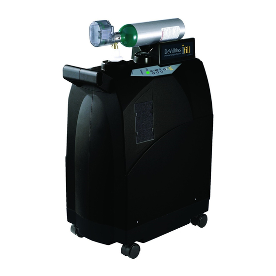
- Page 25 F I G U R E S , D I A G R A M S , A N D V I E W S figure 6 - exterior, cYLinDer attacHeD to fiLL connector PulseDose Conserving Device Cylinder Fill Connector Fill Port Cradle Collar...
- Page 26 F I G U R E S , D I A G R A M S , A N D V I E W S figure 7 - exterior, ifiLL cYLinDers W/conserVing DeVice & continuous fLoW reguLator Rotary Selector PulseDose Conserving Device Pressure...
- Page 27 F I G U R E S , D I A G R A M S , A N D V I E W S figure 8 - interior, front VieW - pressure intensifier Fill Connector Fill Port Collar Support Grommet Pressure Switch...
- Page 28 F I G U R E S , D I A G R A M S , A N D V I E W S figure 9 - interior, rigHt siDe VieW Intake Bacteria Filter Extension Tube Pressure Intensifier Compressor Pressure Exhaust Tubing Tubing 1/2”...
- Page 29 F I G U R E S , D I A G R A M S , A N D V I E W S figure 10 - interior, top VieW - cHeck VaLVes anD orifice Purge Harness Assembly Check Valve Check Valve Sieve Bed Sieve Bed...
- Page 30 F I G U R E S , D I A G R A M S , A N D V I E W S figure 11 - interior, BeDs anD accumuLator tank Support Grommet Cylinder Detect Switch O2 Inlet to 2nd Stage Sieve Bed Test Point...
- Page 31 F I G U R E S , D I A G R A M S , A N D V I E W S figure 12 - interior, rear top VieW Main PC Board Tubing 1/8” ID Final Bacteria Filter Three-Way Valve...
- Page 32 F I G U R E S , D I A G R A M S , A N D V I E W S figure 13 - interior, compressor Ladder Clamps AC Wire Harness PR Valves Pressure Exhaust Tubing 1/2” ID Tubing 3/8”...
- Page 33 F I G U R E S , D I A G R A M S , A N D V I E W S figure 14 - interior, rear LoWer VieW exHaust muffLer & Harness (535D) AC Wire Exhaust Muffler Harness Pressure Exhaust Tubing 1/2”...
- Page 34 F I G U R E S , D I A G R A M S , A N D V I E W S figure 15 - interior, four-WaY anD rotarY VaLVes Intensifier Four-Way Valve Four-Way Valve Wire Harness Rotary Valve Ladder Tubing 3/8”...
- Page 35 F I G U R E S , D I A G R A M S , A N D V I E W S figure 16 - interior, Bottom of intensifier 1st Stage Cylinder O2 Outlet to 2nd Tubing 1/2” ID Stage (Silicone) Intensifier...
- Page 36 F I G U R E S , D I A G R A M S , A N D V I E W S figure 17 - interior, front LoWer VieW intensifier remoVeD O2 Accumulator Tank Rotary Valve Tubing 1/2” ID Outlet Fitting Wire Harness (Silicone)
- Page 37 F I G U R E S , D I A G R A M S , A N D V I E W S figure 18- interior, insiDe VieW of rigHt coVer Fastener Receptacle Ribbon Cable Hour Meter Right Cover LT-1929...
- Page 38 F I G U R E S , D I A G R A M S , A N D V I E W S figure 19 - interior, Left siDe VieW Fill Connector Cylinder Detect Long-Life Switch Intake Filter Pressure Plexiglas Intensifier...
- Page 39 F I G U R E S , D I A G R A M S , A N D V I E W S figure 20 - interior, internaL rear VieW Long-Life Intake Filter Main PC Board Final Bacteria Filter Extension Tube Air Inlet Check...
-
Page 40: Pneumatic And Wiring Diagrams
F I G U R E S , D I A G R A M S , A N D V I E W S figure 21 - pneumatic Diagram LT-1929... - Page 41 F I G U R E S , D I A G R A M S , A N D V I E W S figure 22 - Wiring Diagram LT-1929...
-
Page 42: Ordering Information And Parts List
HAVE TO BE RETURNED TO THE FACTORY . Before returning parts or units to the factory, call the DeVilbiss Healthcare Customer Service Department (800-338-1988 or 814-443- 4881) to obtain a return authorization number . Include in the package a note indicating the return authorization number along with your company name, address, phone number, and account number . -
Page 43: Parts List
O R D E R I N G I N F O R M A T I O N A N D P A R T S L I S T parts List tools and accessories Oxygen Analyzer R217P62 or R218P12 Test Magnets 535D-618 components... -
Page 44: Parts List
O R D E R I N G I N F O R M A T I O N A N D P A R T S L I S T components 535D 535i Hour Meter PV5LD-617 PV5LD-617 Labels • Indicator LED Panel Label 535D-620 535D-620 •... -
Page 45: Specifications
DeVilbiss ifill personal oxygen station Operating Temperature: ..........................41º to 95ºF (5º to 35ºC) Operating Humidity Range: . - Page 48 ® DeVilbiss , OSD , PulseDose and DeVilbiss iFill are registered trademarks of DeVilbiss Healthcare . ® Snoop is a registered trademark of SWAGELOK © 2015 DeVilbiss Healthcare LLC . 03 .15 All Rights Reserved . LT-1929 Rev . D...
Need help?
Do you have a question about the iFill 535D and is the answer not in the manual?
Questions and answers