Rotex GCU compact 315 Installation And Maintenance Instructions Manual

Gcu compact series floor-standing gas condensing boiler with integrated heat storage
Table of Contents

Advertisement

For certified companies
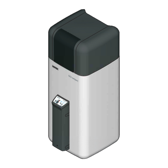
ROTEX
GCU compact
Installation and maintenance
instructions
Floor-standing gas condensing boiler with integrated
heat storage

0063 CR 3574
Types
GCU compact 315
GCU compact 320
GCU compact 515
GCU compact 520
GCU compact 524
GCU compact 528
GB
Edition 06/2017
GCU compact 315 Biv
GCU compact 320 Biv
GCU compact 515 Biv
GCU compact 520 Biv
GCU compact 524 Biv
GCU compact 528 Biv

Advertisement

Table of Contents
loading
Need help?

Need help?

Do you have a question about the GCU compact 315 and is the answer not in the manual?

Questions and answers

Summary of Contents for Rotex GCU compact 315

  • Page 1 Floor-standing gas condensing boiler with integrated heat storage  0063 CR 3574 Types GCU compact 315 GCU compact 315 Biv GCU compact 320 GCU compact 320 Biv GCU compact 515 GCU compact 515 Biv GCU compact 520 GCU compact 520 Biv...
  • Page 2 Declaration of conformity FA ROTEX GCU2 - 06/2017...
  • Page 3: Table Of Contents

    Design and components ....11 3.1.1 GCU compact 315 / 320 ....11 Controller and electronic components ..45 3.1.2...
  • Page 4 15.1 Data for designing the flue gas pipe ..84 15.2 Emissions measurement ....84 FA ROTEX GCU2 - 06/2017...
  • Page 5: General Safety Precautions

    General safety precautions General safety precautions 1.1 Particular safety instructions WARNING! Heating devices that have not been correctly set up and installed can impair the function of the heating device and/or cause serious or fatal injuries to the user. ● Work on the GCU compact (such as set-up, servicing, connection and initial start-up) must only be carried out by persons who are authorised and who have successfully completed qualifying technical or vocational training and who have taken part in advanced training sessions recog- nised by the relevant responsible authorities for the specific activity.
  • Page 6: Observing The Instructions

    – ROTEX GCU compact: – Operating instructions for the operator. Danger of explosion – Operating manual for the operator – ROTEX RoCon BF: operating instructions. Risk of burning or scalding – When additional ROTEX components are connected: the associated installation and Risk of poisoning operating instructions.
  • Page 7: Safety Instructions For Installation And Operation

    1.2.2 Use as intended authorised and who have successfully The ROTEX GCU compact may only be used for completed qualifying technical or the heating of hot water heating systems. It may...
  • Page 8: Device Installation Room

    ● Make sure that there is an outside air opening of at least 150 cm for ambient-air dependent or partial ambient-air independent operation. ● Do not operate the ROTEX GCU compact in ambient-air dependent operation in rooms with aggressive vapours (e.g. hair spray,...
  • Page 9: Requirements For The Heating Water

    1.2.7 Fuel cause a considerably reduced service life of the equipment. The responsibility for this lies solely The ROTEX GCU compact is factory set to the with the operator. gas type indicated on the burner sticker and on the settings type plate and adjusted to the gas pressure indicated on the burner sticker.
  • Page 10: Handover To Operator And Warranty

    Handover to operator and warranty Handover to operator and warranty 2.1 Instruct the owner 2.2 Warranty conditions ● Before you hand over the heating system, explain to the The legal guarantee conditions fundamentally apply. Our war- owner how he/she can operate and check the heating ranty conditions beyond that can be found online on your sales system.
  • Page 11: Product Description

    3.1 Design and components 3.1.1 GCU compact 315 / 320  Fig. 3-1 Design and components of GCU compact 315 / 320 - top view (for legend designations, see tab. 3-1)  Fig. 3-3 Design and components GCU compact 315 / 320 - schematic diagram (for legend designations, see tab.
  • Page 12: Gcu Compact 515 / 520 / 524 / 528

    Design and components GCU compact 515 / 520 / 524 / 528 - schematic diagram (for legend designations, see tab. 3-1)  Fig. 3-5 Design and components GCU compact 515 / 520 / 524 / 528 - front view (for legend designations, see tab. 3-1) FA ROTEX GCU2 - 06/2017...
  • Page 13 Product description  Fig. 3-7 Design and components  diagram for GCU compact 515 / 520 / 524 / 528 (for legend designations, see tab. 3-1) FA ROTEX GCU2 - 06/2017...
  • Page 14: Brief Description

    Tab. 3-1 Legend for fig. 3-1 to fig. 3-7 3.2 Brief description The ROTEX Gas Combi Unit 2 (GCU compact) is a fully preas- exchanger, which is made from a stainless steel corrugated pipe sembled gas condenser unit integrated in a hot water storage (1.4404), and is completely immersed in the storage tank water.
  • Page 15 There are no low flow or unheated zones on the domestic water The calorific value engineering makes optimum use of the energy side with the ROTEX GCU compact. It is not possible for sludge, contained in the heating gas. The flue gas is cooled down in the rust or other sediments to be deposited, as can be the case with boiler –...
  • Page 16: Set-Up And Installation

    Incorrectly erected and installed gas devices may not operate properly and are dangerous for the health and safety of individuals. ● The ROTEX GCU compact may only be installed by heating technicians authorised and trained by gas or energy supply companies.
  • Page 17 Set-up and installation Dim. GCU compact 3xx GCU compact 5xx 1380 1895 1725 1720 2050 Tab. 4-1 Connection and installation dimensions of the GCU compact in mm (based on fig. 4-1, fig. 4-2, fig. 4-10, fig. 4-16 to fig. 4-18)
  • Page 18: Connecting Dimensions For The Heating And Hot Water Connections

    Set-up and installation 4.1.1 Connecting dimensions for the heating and hot water connections GCU compact 3xx Front Rear  Fig. 4-4 Connection dimensions of the GCU compact 3xx (top view) For legend of position numbers, see tab. 3-1 Fig. 4-3 GCU compact 3xx connection dimensions (view from the ...
  • Page 19 Fig. 4-6 Connection dimensions GCU compact 5xx (top view) For legend of position numbers tab. 3-1 To prevent increased cooling losses ROTEX recom- mends installation of SKB gravity brake systems 16 50 70) or syphoning (lead the connection lines straight downwards) of the drinking water connections.
  • Page 20: Installation Versions

    2x75 cm²) Installation version 3 Rear ventilation opening (150 cm The ROTEX GCU compact is not placed directly below the roof. Fig. 4-7 Installation versions for the GCU compact The dual pipe for the combustible air supply and flue gas duct The ROTEX GCU compact is designed basically for ambient air- runs through the roof truss.
  • Page 21: Partial Ambient Air-Independent Mode

    Appropriate measures must be taken to ensure that the burner cannot be operated if the ventilation opening is closed. The ROTEX GCU compact with the SET GCU1 and the LAS – The installation shaft where the flue gas line runs must be rear connection line SET H or SET K is connected to the exterior wall ventilated.
  • Page 22 – as for B , but connection to associated flue gas pipe described in this manual (see chap. 4.5.1), a suitable arith- (ROTEX system) including flue gas opening metical dimensioning verification is required. – For data on dimensioning calculation, see tab. 15-1.
  • Page 23: Transport And Delivery

    – The GCU compact must be installed protected from frost. Surface temperatures, minimum distance WARNING! The plastic wall of the storage tank of the ROTEX GCU compact can melt under the effects of external heat (>80 °C) and, in the extreme case, can catch fire.
  • Page 24: Installing The Unit

    4.4.2 Installing the unit WARNING! The ROTEX GCU compact is top-heavy when unfilled and could tilt over during transport. That could put persons in danger or damage the unit. ● Secure the ROTEX GCU compact well, transport carefully, use handles.
  • Page 25: Removing The Cover And Thermal Insulation

    ● Unhook the protective cover from the rearward facing holding burls, lift at the back and remove to the front. Fig. 4-11 Remove the protective cover Fig. 4-12 ROTEX GCU compact without protective cover CAUTION! The thermal insulation (fig. 4-12, item A) consists of pressure- sensitive EPP moulded parts that can be easily damaged if not handled correctly.
  • Page 26: Air/Flue Gas System (Las)

    – Each flue gas line must be installed with a suitable test adapter for checking and setting the combustion values. The ROTEX LAS construction sets each include a test adapter (D8PA, 15 50 79.00 93). – Depending on the local building regulations, inspection com- ponents must be installed in the required locations.
  • Page 27: Connecting A Flue Gas Line

    SET H (see chap. 4.5.3) - (for dimensions, see tab. 4-1) fig. 4-15 and chap. 15.1. Natural gas E/H (G20) Flue gas mass flow Natural gas LL/L (G25) Burner load Liquid gas (G31) Fig. 4-15 Flue gas mass flow in relation to the burner load ROTEX GCU compact (all types)
  • Page 28 Set-up and installation Front view Inspection section Test adapter Fig. 4-17 Top view of the GCU compact flue gas connection to the side with SET H (see chap. 4.5.3) - (for dimensions, see tab. 4-1) In some cases, the resonance in the flue gas system can amplify the noise at the mouth of the flue gas duct.
  • Page 29: Flue Gas System Kits

    Set-up and installation 4.5.3 Flue gas system kits Fig. 4-18 Flue gas system kits If needed Flue gas connection, left See tab. 4-1 Flue gas connection, right (PA) Test adapter Flue gas connection, rear (O) Flue gas connection, top...
  • Page 30: Water Connection

    ● Install a dirt filter or sludge separator in the heating return flow (see chap. 1.2.6). CAUTION! If the ROTEX GCU compact is connected to a cold water line where steel pipes are used, chips can go into the special steel corrugated pipe heat exchanger and remain there. This can lead to contact corrosion damage and subsequently to leakage.
  • Page 31: Aligning The Connections Of The Heating Supply

    1.2.6. ● Install the ROTEX GCU compact close to the withdrawal point to dispense with the need for a circulation line. If a circu- lation line is essential, it must be installed in accordance with the schematic diagrams in chap.
  • Page 32: Connecting Hydraulic Lines

    Comply with the stipulated tightening torque (see chap. 12.3). – Install the line in such a way that the protective cover of the ROTEX GCU compact is simple to put on after assem- bly. – Connect the water for filling or refilling the heating system as specified by EN 1717/EN 61770 to avoid contamina- tion of drinking water by return flow.
  • Page 33: Connect The Condensate Drain

    Set-up and installation WARNING! There is a danger of scalding at hot water temperatures over 60 °C. This is possible when using solar energy if an external heater is connected, the Legionella protection is activated, or the target hot water temperature is set to be greater than 60 °C. ●...
  • Page 34: Electrical Connection

    ● The equipment covers and maintenance opening covers must be re-fitted immediately after completion of the work. All ROTEX GCU compact control and safety devices are con- nected ready for use and tested. Modifications on the electrical installation are dangerous and prohibited. The operator alone Fig.
  • Page 35 ● Effective strain relief in the controller housing by means of cable ties must be ensured for all cables connected to the ROTEX GCU compact. ● Check the holding force of the strain relief. ● Bring the controller housing back into the vertical operating position.
  • Page 36: Integrated Heating Circulation Pump And 3-Way Valve

    ● Close the front panel and screw in the locking screw. The use of temperature sensors that are not approved or unsuitable for the unit can lead to major malfunctions during regular operation of the ROTEX GCU compact and impair the CAUTION! control function of the unit.
  • Page 37: Connecting The Rocon Ot1 External Temperature Sensor

    - see chap. 4.7.9 and function "Operating chap. 4.7.8). A connected room thermostat has to be activated by mode switchover over EXT input" in the "ROTEX controller parameter [Room thermostat] on the RoCon BF controller. RoCon BF" documentation.
  • Page 38: Mixer Module Rocon M1

    Fig. 4-38 Connect the J8 sensor connector to the PCB control panel ● Close the control panel. 4.7.5 Mixer module RoCon M1 The RoCon M1 mixer module can be connected to the ROTEX GCU compact (J13 circuit board connector) and is controlled by the electronic boiler controller.
  • Page 39: External Switching Contact

    The operating mode has an effect on the direct circuit of the a few sparks can cause major explosions. ROTEX GCU compact as well as all other heating circuits con- ● Before working on gas carrying parts, always close the nected to this device as an option.
  • Page 40: Removing/Attaching The Heat Cell Panelling

    Set-up and installation 4.8.4 Checking the gas presetting ● Compare the available gas type with the position set for the setting screw on the safety gas control block (fig. 4-44, item 3.1). – 1 = Natural gas – 2 = Liquid gas ...
  • Page 41: Filling The System

    This adjustment must be appropriately labelled with a suit- able burner settings sticker and an entry on the settings Fill the ROTEX GCU compact only after completion of all instal- type plate (fig. 3-2 / fig. 3-5, item 33). lation work in the order shown below.
  • Page 42: Start-Up

    – In the event of burner starting problems, see chap. 7.3.4. CAUTION!  Automatic calibration of the GCU compact and adjust- If the ROTEX GCU compact is not started up properly, it could ment of the gas valve complete. lead to material or environmental damage. ...
  • Page 43: After Start-Up

    5.1.4 After start-up housing ● Installing the protective cover (see chap. 4.4.3). Tab. 5-1 Start-up control values for GCU compact 315 and ● Check all the points on the "Checklist after start-up" (see GCU compact 515 for various gas types chap.
  • Page 44: Checklists For Start-Up

    Start-up Checklists for start-up Checklist before start-up  Is the ROTEX GCU compact properly installed in accordance with a permitted set-up and without any discernible damage?  Combustion air supply secured?  Adequate ventilation and extraction in the heating room with limited ambient air-independent (separate flue gas/air supply line) or ambient air-dependent operation? ...
  • Page 45: Controller And Electronic Components

    6.1 Operating elements on the boiler control panel The ROTEX GCU compact is fitted with the ROTEX RoCon BF controller. The integrated digital control system actuates a direct heating circuit and a storage tank charging circuit. It can be extended in many ways with accessory components.
  • Page 46: Replacing The Rocon B1 Control Panel

    Touching live parts can result in an electric shock and lead to against unintentional restart. potentially fatal injuries and burns. ● Before beginning work on the ROTEX GCU compact, Removing the control panel disconnect it from the power supply (fuse, switch off the main ●...
  • Page 47: Replacing The Inflow Temperature Sensor / Return Flow Temperature Sensor And Pressure Sensor

    Controller and electronic components 6.3.1 Replacing the inflow temperature sensor / return flow temperature sensor and pressure sensor WARNING! There is a danger of scalding from heating water. Sensors are connected directly to the pressurised heating water. ● Before removal of the sensors, close the ball cocks on the boiler inflow and boiler return flow, and depressurise the system with the KFE cock.
  • Page 48: Replacing The Internal Mixer Sensor For Heating Support

    Guide the cable into The insertion depth is marked on the ROTEX hot water the controller housing, connect to terminals 5 and 6 of PCB storage tank by a coloured marking depending on the storage plug J8 and put on the plug.
  • Page 49: Heat Cell With Gas Burner

    Heat cell with gas burner Heat cell with gas burner 7.1 Design and brief description  Fig. 7-2 Components of the GCU compact heat cell:  Gas section – exploded view (for legend, see tab. 7-1)  Fig. 7-1 GCU compact - heat cell (for legend, see tab.
  • Page 50 Heat cell with gas burner Ignition electrodes Ionisation electrode Burner flange Burner blower Venturi nozzle Gas connector pipe Gas connection G ½" IG with connected gas hose Safety gas control block Gas valve connection adapter Condensate pipe with overfill protection Flue gas collector Securing stirrup for gas connection line(2x) Supply air manifold...
  • Page 51: Safety Function

    Requirements: The cause of the malfunction has been rectified, the burner is connected to the electrical system. 1. Switch on the ROTEX GCU compact. 2. Push the Exit button (fig. 6-1, item 13) for at least 5 s. ...
  • Page 52: Adjustment Values

    Compare with the information on the yellow sticker attached to the burner housing housing Tab. 7-3 Set flue gas setting values for GCU compact 315 and Tab. 7-7 Set flue gas setting values at "Base Load" for all GCU compact 515 for various gas types...
  • Page 53: Starting Problems - Calibrating The Firing Unit, Setting The Burner Blower Starting Output And Gas Volume

    Compare the measured values with You can find more detailed explanations and possible setting values for these pa- the specified setting values (see chap. 7.3.1). rameters in the "ROTEX RoCon BF" controller operating instructions. a) If the O concentrations lie within the permissible 7.3.4 Starting problems - calibrating the firing unit,...
  • Page 54: Setting Ignition And Ionisation Electrodes

    Heat cell with gas burner 1. Switch the ROTEX GCU compact off and then on again. 5. Confirm the changes with a brief push of the rotary switch. 2. Set the rotary switch to the "Configuration" position. 6. Switch the ROTEX GCU compact off and then on again.
  • Page 55: Dismantling The Burner

    Removing the burner ● Block gas supply. ● Disconnect the ROTEX GCU compact from the power supply (fuse, main switch switched off) and secure against uninten- tional restart. ● Remove the protective cover (see chap. 4.4.3).
  • Page 56: Burner Installation

    Mains plug, blower x fixing screw (burner flange/boiler body) Fig. 7-6 Removing the burner GCU compact 315 / 320 / 515 / 520 (Biv) GCU compact 524 / 528 (Biv) Fig. 7-8 Cleaning the burner surface ● Inspect the burner surface (fig. 7-7, item 3) for damage, renew if necessary.
  • Page 57: Hydraulic Connection

    Cold water distribution network WARNING! Hot water distribution network To prevent flue gas from escaping, the storage tank must be Heating flow filled to overflow when starting up the ROTEX GCU compact. Heating return flow Mixing circuit Circulation WARNING! Check valve, return valve Non-return valves High temperatures can occur in the solar storage tank.
  • Page 58 Hydraulic connection Fig. 8-1 GCU compact 3xx (example) with DrainBack solar (for legend, see tab. 8-1) Fig. 8-2 GCU compact 5xx Biv with pressurised solar system (for legend, see tab. 8-1)
  • Page 59: Service And Maintenance

    ROTEX GCU compact. Tests performed during the annual service ● Damage repair to power and gas lines on the ROTEX – General condition of the heating system, visual inspection of GCU compact may only be carried out by heating techni- connections and pipes.
  • Page 60: Checking And Cleaning The Condensate Drain

    Service and maintenance 9.2.2 Checking and cleaning the condensate drain 9.2.3 Checking and cleaning the burner WARNING! DANGER OF EXPLOSION! Danger of scalding from hot storage water. Escaping gas is a direct threat to human health and safety. Even ● Before dismantling the condensate drain, allow the storage a few sparks can cause major explosions.
  • Page 61: Filling, Topping Up The Storage Tank

    ● Fill the storage tank of the GCU compact until water escapes out of the overflow connection (fig. 9-3, item 2). ● Remove the filling hose with non-return valve (1/2"). GCU compact 315 / 320 / 515 / 520 (Biv) GCU compact 524 / 528 (Biv)
  • Page 62: Filling, Topping Up The Heating System And Storage Tank Charging Circuit

    Service and maintenance 9.2.5 Filling, topping up the heating system and Filling hose with return flow Water tap storage tank charging circuit inhibitor (and manometer Automatic bleeder KFE cock Pressure gauge Heater ball cock - inflow  Heater ball cock - return 3UV DHW DANGER! ...
  • Page 63: Venting The Hydraulic Block

    3-way changeover valves integrated in the ROTEX GCU compact. Any air present can escape via the automatic vent valve during the air purge and the hydraulic circuit connected to the ROTEX GCU compact is evacuated. The activation of this function does not replace correct venting of the heating circuit.
  • Page 64: Faults And Malfunctions

    10.1 Troubleshooting Troubleshooting ● Detecting and remedying the cause of the malfunction. The electronics of the ROTEX GCU compact ● Non-interlocking faults (see chap. 10.3) are indicated for as – signal a fault by red backlight in the display, and long as the malfunction exist.
  • Page 65 ● Throttle maximum pump output (setting of parameter noises [Max Perform Pump] reduce gradually – not below Badly balanced heat distribution system 65%). ● Carry out hydraulic balancing. 1) See "ROTEX RoCon BF" controller documentation Tab. 10-1 Possible faults on the GCU compact...
  • Page 66: Fault Codes

    Faults and malfunctions 10.3 Fault codes Code Component/Designation Error or t defective (cable break, short circuit). During calibration, difference from prior value was too high (unclean supply air, electrode re- placement, electrode defective). E129 Inflow temperature exceeds limiter temperature (overtemperature, no heat dissipation) E130 Return flow temperature exceeds limiter temperature (overtemperature, no heat dissipation) E132...
  • Page 67 Faults and malfunctions Code Component/Designation Error Return flow temperature exceeds monitor temperature (overtemperature, no heat dissipa- tion) Inflow flow temperature exceeds monitor temperature (overtemperature, no heat dissipation) Undervoltage with 230 V mains voltage or 18 V internal DC voltage (electronic fault, switch device on/off).
  • Page 68 Faults and malfunctions Code Component/Designation Error Possible fault rectification Internal mixer sensor ● Check cable, terminal and plug connec- tions. External temperature sensor Measured value outside measuring range, ● Replace temperature sensor. temperature sensor defective. Storage tank temperature sensor EEPROM ●...
  • Page 69: Rectifying Burner Malfunctions And Stb Malfunctions

    "Manual Operation" special function on the controller (see en- closed "ROTEX controller RoCon BF" operating instructions). When the 3-way valves are intact the ROTEX GCU compact switches to heating operation. The required inflow temperature can be adjusted with the rotary switch.
  • Page 70: Taking Out Of Operation

    If no heating and no hot water supply is needed over a long ● When using the KFE filling connection (accessory period the ROTEX GCU compact can be temporarily shut down. KFE BA, 16 52 15): However, ROTEX recommends putting the system into standby Remove the cover panel on the handle and unscrew the mode (see the documentation concerning "ROTEX controller).
  • Page 71: Draining The Heating Circuit And Hot Water Circuit

    1. Switch off the main switch and secure against restarting. 2. Close the gas stop valve. 3. Connect the drain hose to the KFE cock of the ROTEX GCU compact. Fig. 11-3 Completing the KFE fill- Fig. 11-4 Screwing the KFE filling...
  • Page 72: Technical Data

    = 45 °C. The specif. water flow acc. to EN 15502 is the domestic water flow at an average temperature increase of 30 K, which the ROTEX GCU compact can supply if two draw-off procedures each of 10 minutes duration are performed one after the other, assuming a charging temp. of 65 °C. A delay of 20 minutes between the two draw-off procedures is usually assumed.
  • Page 73: Gcu Compact 5Xx

    = 45 °C. The specif. water flow acc. to EN 15502 is the domestic water flow at an average temperature increase of 30 K, which the ROTEX GCU compact can supply if two draw-off procedures each of 10 minutes duration are performed one after the other, assuming a charging temp. of 65 °C. A delay of 20 minutes between the two draw-off procedures is usually assumed.
  • Page 74: Integrated Gas Boiler

    Technical data 12.1.3 Integrated gas boiler Type (1)* GCU compact (Biv) Parameters Unit 315 / 515 320 / 520 Permitted ambient temperature °C 1 - 60 Product ID (CE number) (3)* CE-0063 CR 3574 Automatic firing unit Elster QCM434-R1 Safety gas control block Elster CES10 Burner fan ebmpapst NRG 118/0800-3612...
  • Page 75: Information On The Type Plate

    Technical data 12.1.5 Information on the type plate Equipment type Unit type Product ID (CE number) Rated thermal load Q Nominal output P (80/60 °C) Nominal thermal output during condensation operation P (50/30 °C) NOx class (EN 15502) Voltage supply U Electrical power consumption elmax Degree of protection Net weight...
  • Page 76: Product Fiche (Characteristics Pursuant To The European Energy Labelling Directives)

    Details and precautions on installation, maintenance and assembly can be found in the installation and or operation manuals. Energy labels and product fiches for additional combinations, packages and other products can be found at www.rotex-heating.com. Sound power in heating mode, measured according to the EN 12102 under conditions of the EN 14825.
  • Page 77: Gas Type, Connection Pressures

    Technical data 12.2 Gas type, connection pressures Gas type Nominal pressure in mbar Min. inlet pressure in mbar Max. inlet pressure in mbar Natural gas E/H Natural gas LL/L Liquefied petroleum gas 42.5 57.5 Tab. 12-6 Permitted gas inlet pressure Country of destination Appliance category Nominal connection pressure in...
  • Page 78: Flow Rate And Residual Feed Height

    Technical data 12.4 Flow rate and residual feed height 12.5 Temperature sensor p Sensor resistance Temperature Residual feed height Modulation range Heating network flow Fig. 12-4 Resistance characteristics of the temperature sensor Fig. 12-2 Residual feed height GCU compact (heating side) Temperature sensor Type Specification *...
  • Page 79: Electrical Connection Diagram

    Technical data 12.6 Electrical connection diagram  Fig. 12-5 Wiring diagram ROTEX GCU compact (for legend, see tab. 12-10)
  • Page 80 Technical data  Circulation pump (optional) RoCon BE1 3-pin circuit board connector with mains  3UVB1 circuit board pump cable  3-way mixer valve RJ45 CAN 4-pin PCB connector: Connection 3-way  3UV DHW BUS - Control unit connection mixer valve 3UVB1 3-way distribution valve DIP switch (device type) 6-pin circuit board connector (AUX connec-...
  • Page 81: Notes

    Notes 13 Notes...
  • Page 82 Notes...
  • Page 83: List Of Keywords

    Overfill protector ... . 50 Electrical installation ... . 34 Electronic control ....15 FA ROTEX GCU2 - 06/2017...
  • Page 84: For The Chimney Sweep

    15.2 Emissions measurement Special Level The check measurement can be made by an easily selectable automatic Emission Measurement function (see also "Operating Instructions ROTEX RoCon BF controller"). Manual Operation ● Push the Exit button for at least 5 s. ...

Table of Contents