Table of Contents
Advertisement
Advertisement
Table of Contents

Subscribe to Our Youtube Channel
Related Manuals for Rotex A1 BO


Summary of Contents for Rotex A1 BO
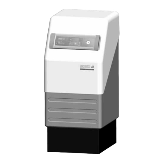
- Page 1 ROTEX A1 BO Oil condensing boiler Installation and maintenance instructions 0645 BM Type Rated thermal output ROTEX A1 BO 15bio 12–15 kW Edition 10/2007 ROTEX A1 BO 20i 12–20 kW ROTEX A1 BO 27i 20–27 kW ROTEX A1 BO 35i 25–35 kW...
- Page 2 Guarantee and conformity ROTEX provides a warranty for material and manufacturing defects according to this statement. Within the warranty period, ROTEX undertakes to have the unit repaired free of charge by a person assigned by the company. ROTEX reserves the right to replace the unit.
-
Page 3: Table Of Contents
Wiring diagram ..................38 FA ROTEX A1 BO - 10/2007... - Page 4 For the chimney sweep ..............72 FA ROTEX A1 BO - 10/2007...
-
Page 5: Safety
– ROTEX A1 BO Instruction manual for the user/owner. The document is included in the scope of delivery. – The documentation of the ROTEX Control being used. It is included in the scope of delivery of the Control. Warning signs and explanation of symbols Meaning of the warnings Warnings in this manual are classified according into their severity and probability of occurrence. -
Page 6: Avoid Danger
Proper use The oil condensing boiler ROTEX A1 BO can only be used for heating hot water heating systems. It must be installed, connected and operated only according to the information in this manual. The oil condensing boiler ROTEX A1 BO may be operated only in combination with a control unit approved by ROTEX (see conformity declaration on page 2 of this manual). -
Page 7: Instructions For Operating Safety
• Operate the oil condensing boiler only if sufficient combustible air supply is guaranteed. If operating the oil condensing boiler independently of the ambient air with an air/flue system (LAS) with dimensions according to ROTEX-Standard, this is automatically guaranteed and there will be no further conditions required of the unit installation room. -
Page 8: Product Description
Product description Boiler design and components Product description A1 BO 15bio / A1 BO 20i A1 BO 27i/A1 BO 35i A1 Schematic drawing Fig. 2-1 Boiler components – View from the front Fig. 2-2 Diagram A1-boiler A1 BO 15bio / A1 BO 20i A1 BO 27i/A1 BO 35i Fig. -
Page 9: Brief Description
Operating mode The ROTEX oil condensing boiler A1 BO is designed in such a way that it can be operated independent of ambient air. The burner suctions the combustion air directly in through an installation shaft or a double-walled flue gas pipe. This operating mode has several advantages: –... -
Page 10: Set-Up And Installation
Incorrect set-up and installation would make the manufacturer's guarantee void. If you have questions, please contact our Technical Customer Service. Dimensions and connection dimensions Fig. 3-1 Dimensions of the model versions, side view Fig. 3-2 Dimensions and connection dimensions of the model versions, rear view FA ROTEX A1 BO - 10/2007... - Page 11 1040 1100 1100 1340 1890 1650 1470 2020 1770 1590 2140 1890 1100 1730 1480 1220 1850 1600 1340 1970 1720 Tab. 3-1 Installation dimensions for oil condensing boiler A1 B0 in mm FA ROTEX A1 BO - 10/2007...
-
Page 12: Different Set-Ups
Set-up and Installation Different set-ups The oil condensing boilers in the series A1 BO are basically designed for operation independent of ambient air. They are fitted with a concentric flue gas/air supply pipe DN 80/125. ROTEX recommends operating the oil condensing boiler independently of ambient air. -
Page 13: Operation Independent Of Ambient Air
In the external area, the outer air gap serves as heat insulation for the flue gas pipe. If the wall opening is less than one metre above the ground, ROTEX recommends sending the combustible air through a separate air supply pipe (PPW-ZR, 15 50 79.00 66) at a height of approx. -
Page 14: Ambient Air Dependent Operation
Set-up and Installation 3.2.3 Ambient air dependent operation The oil condensing boiler of series A1 BO can also be connected depending on ambient air. The unit suctions the combustible air from the installation room through the ring-shaped gap in the enveloping pipe. -
Page 15: Setting Up An Oil Condensing Boiler
• Use only a metallic filter cup (never Plexiglas). Set-up in garages The oil condensing boilers of series A1 BO are basically suitable for being set-up and operated in garages. Requirements: – Operation independent of ambient air, – A durable instruction manual placed in a very visible place near the boiler, –... -
Page 16: Setting Up The Unit
The features of the flue system must be recognisable on the installed system. • Place the nameplate of the flue system in the installation room. We recommend using the associated ROTEX flue gas kits. They satisfy all requirements and are also fitted with special acid-proof seals. - Page 17 – The minimum height of the flue gas pipe must be 2 m in order to avoid malfunction when starting or while operating the burner. Set-up version A1 BO 15bio A1 BO 20i A1 BO 27i A1 BO 35i (ref. fig 3-4)
-
Page 18: Connecting The Flue Gas Pipe To The Oil Condensing Boiler
Connection: 14 478 (ref. to chapter 3.5.1): We recommend using the associated ROTEX flue gas kits (see fig 3-5). They satisfy all requirements and are also fitted with special acid-proof seals. • Connect the oil condensing boiler to the flue system in the installation room (for connection dimensions refer to fig 3-6 and tab. -
Page 19: Flue System Kits
Set-up and Installation 3.5.3 Flue system kits Tab. 3-5 Plastic (PP) flue system kits * If required FA ROTEX A1 BO - 10/2007... -
Page 20: Water Connection
• Install a dirt filter in the heating return flow. – Water shortage protection: The overheating guard of the oil condensing boiler series A1 BO shuts off the oil condensing boiler in the event of a water shortage and locks it for safety reasons. No additional water shortage protection is needed in the construction. -
Page 21: Connect The 3-Way Diverter Valve
There are two 3 m flexible cables connected inside the unit for the mains connection and for the external temperature sensor; they are located in the control panel on the switchboard PCB. Only the optional applications (e.g. mixer circuit, circulation pump) still have to be connected to the boiler control panel. FA ROTEX A1 BO - 10/2007... -
Page 22: Temperature Sensor
Installing the central unit The oil condensing boiler can be operated either with the ROTEX Control ALPHA 23R or with the ROTEX Control THETA 23R. The central control unit to be used is supplied separately and must be fitted at the time of installation (also refer to chapter 5.2). -
Page 23: Connecting The Temperature Sensor
• Connect oil line Whilst doing so, ensure the following: – The inner diameter of the oil line must not be greater than 8 mm. Use the ROTEX VA-Oil oil feeding line or copper pipes with diameter between 6 and 8 mm as the oil line. -
Page 24: Optional Connections
• Check the water pressure on the pressure gauge again and top up with water if necessary. • Close the KFE cock, remove the filling hose and return flow inhibitor from the filling and draining fittings. FA ROTEX A1 BO - 10/2007... -
Page 25: Start-Up
• Switch on the mains switch. Wait for the start phase. • Open the venting screw on the oil filter. • Vent oil line and measure the oil pressure on vacuum meter. The vacuum may be maximum 0.4 bar (better: 0.2 bar). FA ROTEX A1 BO - 10/2007... - Page 26 Change Desired target value Current actual value (flashing) Return to the original operating mode, default display, set target value is saved Fig. 4-3 Manual mode for control THETA 23R (set heat generator temperature) FA ROTEX A1 BO - 10/2007...
-
Page 27: Checklists For Start-Up
Have the burner settings been checked by using a flue gas analyser and readjusted if necessary? The system may only be handed over to the user/owner if all questions can be answered with "Yes". • Fill in the supplied installation and instruction form jointly with the user/owner. FA ROTEX A1 BO - 10/2007... -
Page 28: Control Unit
Controls on the boiler control panel Control unit The ROTEX Oil condensing boiler A1 BO can be operated with the THETA 23R control or only with the ALPHA 23R control. The electronic digital controls are to be used for controlling 2 heating circuits (direct heating circuit, mixer circuit) and a storage tank charging circuit. - Page 29 Select one of the 3 pre-installed timer programmes P1, P2 or P3. You can find further instructions and a more exact description in the documentation for "ROTEX controller THETA 23R". It is included in the scope of supply of the particular electronic control to be ordered separately.
-
Page 30: Control Alpha 23R
Standard display in normal operation: Current day of the week, current date, current time, heat generator temperature and active operating mode (marking bar). 5.1.2 Control ALPHA 23R Only the control and display elements of the ROTEX central control unit ALPHA 23R are described below. For the controls of the complete boiler control panel, see section 5.1.1. Fig. 5-2... - Page 31 Switching timer programming for the switching time programme "Automatic I" (for more detailed information, see ROTEX Control ALPHA 23R). Display All system temperatures and operating statuses of the system components can be shown on the display. If there is a malfunction, a fault code is displayed.
-
Page 32: Changing The Central Unit
Tighten the fixing screws (right handed threads). • Close the bayonet lock (90° rotation). Front view Loosen fixing screws Rear view Tighten fixing screws Fixing screws Fig. 5-3 Install/remove central unit (shown in THETA 23R control) FA ROTEX A1 B0 - 10/2007... -
Page 33: Changing The Boiler Control Panel
5. Pull all connectors from the switchboard PCB (fig. 5-6). 6. Pull out the sensor and the connection cables from the cable ducts of the control panel (fig. 5-7). Fig. 5-6 Pull off the coded connector Fig. 5-7 Pull out the cable FA ROTEX A1 BO - 10/2007... -
Page 34: Changing Cables
– The technical specification of the new cable must correspond to the values of the replaced cables (e.g. conductor cross section). – The circuit board connectors are colour and shape-coded. Do not force the connector! FA ROTEX A1 B0 - 10/2007... -
Page 35: Changing The Sensors
3. Unscrew the flow /return flow temperature sensor using an open-jaw wrench SW 15 (fig. 5-13). 4. Screw in the new flow /return flow temperature sensor and plug in the cable with connector. The connectors are shape-coded. Do not force the connector! FA ROTEX A1 BO - 10/2007... -
Page 36: Changing The Flue Gas Temperature Sensor
3. Bend the pressing springs on the new sensor and push the new sensor into the sensor immersion sleeve. The insertion depth is marked on the ROTEX storage tank by a coloured marking, depending on the storage tank type. 4. Clamp the sensor cable on the connector of the connection terminals 11 and 12 of the 12-pin sensor connector J8, plug in the connector on the switchboard PCB and close the boiler control panel. -
Page 37: Changing The Fuse
If the fuse immediately blows upon switching on again, there is a short circuit in the electrical system. Have a professional electrician remedy the cause of the short circuit before putting in a new fuse. FA ROTEX A1 BO - 10/2007... -
Page 38: Wiring Diagram
Control Wiring diagram Fig. 5-18 Wiring diagram for oil condensing boiler A1 BO (shown with ROTEX THETA 23R Control) Main switch Return flow temperature sensor 4-pin circuit board connector with clamped mains Burner malfunction indicator Flow temperature sensor cable and earthing slots... -
Page 39: Oil Burner
Service screw Recirculation tube Nozzle connection cover Fig. 6-1 Oil burner top view (rear view) Fig. 6-2 Oil burner – Side view from left 13 22 Fig. 6-3 Oil burner – Side view from right FA ROTEX A1 BO - 10/2007... -
Page 40: Safety Function
An inappropriate setting of the oil burner can lead to a prohibited level of pollutant emissions, heavy contam- ination and increased oil consumption. • Burner setting should be carried out only by authorised and recognised heating engineers. FA ROTEX A1 BO - 10/2007... -
Page 41: Settings
Conversion kit for the output range 20–24 kW. 15 46 24 URS25 Conversion kit for the output range 25–27 kW. 15 46 28 URS35 Conversion kit for the output range 33–35 kW. 15 46 35 FA ROTEX A1 BO - 10/2007... -
Page 42: Instructions For Burner Setting
To set some output ranges, a conversion kit URS is needed (see tab. 6-1). Oil nozzles ROTEX recommends using Danfoss Type 80° H oil nozzles to maintain the emission limits as specified in RAL-UZ 46 (see tab. 6-1). 6.3.3 Check vacuum in the oil pump and set the oil pump pressure... -
Page 43: Set Air Quantity
The scale (fig 6-6, pos. 2) shows the set width of the recirculation gap (in mm). If the nozzle tube or the oil preheater are changed or an oil nozzle type different from the regular production type is used, there can be a difference between the scale display and the actual width of the recirculation gap. FA ROTEX A1 BO - 10/2007... -
Page 44: Check And Set Electrode Distance And The Distance Between Oil Nozzles And Air Nozzles
• Check electrode distance and position with feeler gauge "Blue Flame Meter". • If necessary, readjust electrodes by bending them. If the ignition electrodes are worn out, they must be replaced. Notes on replacing the ignition electrodes are given in section 8.2.8. FA ROTEX A1 BO - 10/2007... -
Page 45: Removing/Installing Burner
Fig. 6-10 Loosen service screw on the burner Service screw Bayonet lock 3. Pull off the air supply hose from the burner and rotate sideways. 4. Loosen the service screw (fig 6-10, pos. 1). FA ROTEX A1 BO - 10/2007... - Page 46 2. Screw on the oil hoses on the oil filter. 3. Restore the electrical plug connections and connect the air supply hose to the burner. 4. Install flame tube. 5. Start burner, check functioning and settings (see chapter 6.3). FA ROTEX A1 BO - 10/2007...
-
Page 47: Oil Burner Pump With Le System
15 60 14) for long filter cups in the ventilation oil filters. Use only filters with a maximum of 25 µm. Thermostat Connection plug Heat exchanger PTC heating element LE membrane valve Oil nozzle Fig. 6-13 Oil preheater with LE membrane valve FA ROTEX A1 BO - 10/2007... -
Page 48: Hydraulic Connection
• Pull the 6-pin plug out of the valve drive. • Move diverter valve to centre position with hand lever (fig, 7-1, pos. 2.3) (only possible if the valve drive is already in "Heating" position). FA ROTEX A1 BO - 10/2007... -
Page 49: Hydraulic System Connection
US 150. Note that the hydraulic circuit shown does not claim to be complete and your system planning must therefore still be carried out thoroughly. As a ROTEX certified company you will find other examples for hydraulic system connection concepts on the ROTEX Homepage. -
Page 50: Hot Water Storage Tank (Not Included In Scope Of Supply)
Hot water storage tank (not included in scope of supply) Five types of hot water storage tanks are available for the oil condensing boiler A1 BO (see tab. 7-1). Correct integration of the hot water storage tank into the heating network is shown in fig, 7-2 and fig, 7-3. Alternatively, the ROTEX Solaris System can be integrated for hot water preparation and heating support. - Page 51 220 Litres 250 Litres 160 Litres Tab. 7-2 Thermal output data of the ROTEX hot water storage tank which can be connected to the oil condensing boiler = Cold water temperature = Hot water temperature = Storage temperature = Feed temperature...
-
Page 52: Inspection And Maintenance
Have the service and maintenance carried out by authorised and trained heating engineers once a year and, if possible, before the heating period starts. This will avoid malfunctions during the heating period. ROTEX recommends a service and maintenance contract to ensure regular service and maintenance. Tests during the annual service: –... -
Page 53: Checking The Connections And Pipes
A pH value < 5 despite regular maintenance indicates that the neutralisation medium is spent and the filling quantity is no longer sufficient. In such a case, change the neutralisation medium ( 15 45 75). FA ROTEX A1 BO - 10/2007... - Page 54 3. Lift up condensate treatment unit and drain through the connecting hose (fig. 8-5). 4. Place collector container under the hose connection. Pull out the flexible connecting hose from the condensate treatment unit (fig. 8-6). 5. Pull the condensate treatment unit out from under the boiler. FA ROTEX A1 BO - 10/2007...
- Page 55 The condensate treatment unit is filled through the boiler. For this, open the boiler body, remove the combustion chamber insert and hold a water hose in the combustion boiler (fig. 8-10). Fig. 8-9 Fill condensate treatment unit through the flue gas pipe Fig. 8-10 Fill condensate treatment unit through the boiler FA ROTEX A1 BO - 10/2007...
-
Page 56: Checking The Flue Gas Temperature
8.2.4 Checking the flue gas temperature The flue gas temperature can be checked: – on the boiler control panel by using the Info button (see manual "ROTEX Control"), – on the measuring piece of the flue gas pipe by using a flue gas thermometer. - Page 57 (shown A1 BO 20i) (shown A1 BG 20i) • Only in A1 BO 27i and A1 BO 35i: Remove cylindrical combustion chamber ring. • Remove combustion chamber insert with the help of the combustion chamber key (fig. 8-14 and fig. 8-15).
-
Page 58: Checking The Oil Filter And Cleaning The Oil Pump Filter
If the combustion values do not fall within the target range, the burner must be adjusted accordingly (see chapter 6.3). We recommend completing the service log provided with all the measured values and the tasks performed with date and signature. FA ROTEX A1 BO - 10/2007... -
Page 59: Replacing The Oil Nozzle And Ignition Electrodes
2. Fitting mixing device. Thereby, position the light tube (fig. 8-18, pos. d) between the guide pins in the nozzle lid (see fig. 6-2, pos. 23). Maintain oil-air nozzle distance (Dimension "Y") (see tab. 6-1, chapter 6.3). 3. Plug on ignition cable on the ignition electrodes. FA ROTEX A1 BO - 10/2007... -
Page 60: Faults And Malfunctions
You will find detailed information on the control unit and the boiler control panel as well as on the operating modes and parameter settings in chapter 5 "Control unit" and in the documentation "ROTEX Control" as supplied with the associated Control unit. - Page 61 • Use air supply lines with larger cross-section carbon deposits • Ambient air dependent operation: Check air supply opening (min. 150 cm unlockable air supply opening) Tab. 9-2 Possible malfunctions on the A1 BO (Part 2) FA ROTEX A1 BO - 10/2007...
-
Page 62: Control Unit Fault Signals
Control unit fault signals The control unit detects malfunctions, e.g. sensor disruptions or short-circuits. The type of malfunction is displayed via a fault code. The fault codes are explained in the documentation of the relevant ROTEX control. Burner malfunctions The LED in the reset button of the automatic firing units (fig 6-1, pos. 9) indicates the processes of the burner control. In the normal mode, the LED transmits a brief flashing signal, followed by a long pause. -
Page 63: Rectifying Stl Fault
In the event of a malfunction or incorrect settings of the electronic control, emergency heating operation can be maintained. • Press Manual button (fig 5-1, pos. 13) for approx. 5 s. The indication "Manual operation" appears on the display. • Adjust the desired temperature with the rotary switch (setting range 5–80 °C). FA ROTEX A1 BO - 10/2007... -
Page 64: Taking Out Of Service
If no heating and no hot water supply is needed over a long period, the oil condensing boiler can be temporarily shut down. ROTEX, however, recommends putting the system on Standby mode (see Documentation "ROTEX Control"). The heating system is then protected from frost. -
Page 65: Technical Data
Test as specified in EN 267 Registration number: 5 G 966/2001 Output electrical motor at 2800 min 90 W 90 W 90 W 180 W Protection type IP 40 Tab. 11-2 Basic data oil burner FA ROTEX A1 BO - 10/2007... - Page 66 Danfoss Type FPHB-LE/PTC 50 No. 030 N4257 Motor ACC EB 95C 28/2, 90 W ACC EB 95C 52/2, 180 W Tab. 11-3 Classification of burner components in the A1 BO Integrated connection group Boiler type A1 BO 15bio A1 BO 20i...
- Page 67 922 961 1000 1039 1078 1117 1155 1194 1232 1271 1309 1374 1385 1423 1461 Tab. 11-5 Resistance values of the temperature sensor Remaining pumping height 1000 1200 1400 1600 m / L/h Fig. 11-2 Remaining pumping height A1 BO 15bio Δp Remaining pumping height Flow heating network FA ROTEX A1 BO - 10/2007...
- Page 68 Technical data 1000 1200 1400 1600 1800 2000 m / L/h Fig. 11-3 Remaining pumping height A1 BO 20i Δp Remaining pumping height Flow heating network 1000 1200 1400 1600 1800 2000 m / L/h Fig. 11-4 Remaining pumping height A1 BO 27i Δp...
- Page 69 11 xTechnical data FA ROTEX A1 BO - 10/2007...
-
Page 70: List Of Keywords
Electronic control ....9 Emergency operation ..48 Emission measurement ..30 FA ROTEX A1 BO - 10/2007... -
Page 71: Service Log
Flue gas temperature in the flue gas pipe Temperature of the suction air Carbon monoxide (CO) Maintenance confirmed (Company stamp, Date, Signature) Modifications made to the control setting parameters, other remarks on the heating system Date Signature Comments FA ROTEX A1 BO - 10/2007... -
Page 72: For The Chimney Sweep
Fig. 14-2 Brief instructions for chimney sweep operating mode in symbols ROTEX THETA 23R ROTEX ALPHA 23R Flue gas mass flow Burner output Fig. 14-3 Flue gas mass flow in relation to the burner output FA ROTEX A1 BO - 10/2007...
Need help?
Do you have a question about the A1 BO and is the answer not in the manual?
Questions and answers