Cisco 1120 Hardware Installation
Connected grid router
Hide thumbs
Also See for 1120:
- Installation manual (164 pages) ,
- Quick start manual (10 pages) ,
- Manual (6 pages)
Table of Contents
Advertisement
Quick Links
Advertisement
Chapters
Table of Contents

Related Manuals for Cisco 1120


Summary of Contents for Cisco 1120
- Page 1 Cisco 1120 Connected Grid Router Hardware Installation Guide Last Updated: April 2017 First Published: June 12, 2012 This describes the Cisco CGR 1120 Connected Grid Router, and presets installation and configuration information. Cisco Systems, Inc. www.cisco.com...
-
Page 2: Obtaining Documentation And Submitting A Service Request
An exclamation point (!) or a pound sign (#) at the beginning of a line of code indicates a comment line. Obtaining Documentation and Submitting a Service Request For information on obtaining documentation, using the Cisco Bug Search Tool (BST), submitting a service request, and gathering additional information, see What’s New in Cisco Product Documentation. - Page 3 Consult the dealer or an experienced radio/TV technician for help. Modifications to this product not authorized by Cisco could void the FCC approval and negate your authority to operate the product. The Cisco implementation of TCP header compression is an adaptation of a program developed by the University of California, Berkeley (UCB) as part of UCB’s public domain version of the UNIX operating system.
- Page 5 Unpacking the Router This section includes instructions about how to unpack the Cisco 1120 Connected Grid Router and describes the items that ship with the router. These topics are discussed: Unpacking the Router, page 5 Router Package Contents, page 5...
- Page 6 Router Package Contents Table 1 Router Package Contents Qty. Item Description Cisco 1120 Connected Grid Router Router enclosure with the following components installed: Connected Grid Modules (1 to 2, depending on configuration ordered) with required antennas 2-GB SD Flash Memory Module ...
-
Page 7: Table Of Contents
Installation Safety and Site Preparation This document provides information you should be aware of before installing the Cisco 1120 Connected Grid Router, such as safety information, installation recommendations, and site requirements. These topics are discussed: Safety Recommendations, page 8 ... -
Page 8: Safety Recommendations
Installation Safety and Site Preparation Safety Recommendations Warning: IMPORTANT SAFETY INSTRUCTIONS. This warning symbol means danger. You are in a situation that could cause bodily injury. Before you work on any equipment, be aware of the hazards involved with electrical circuitry and be familiar with standard practices for preventing accidents. -
Page 9: General Site Requirements
Rack Mounting The router is designed for mounting on a DIN rail, or a wall. Cisco recommends that the router not be rack mounted. However, if you install the router in a rack, follow these guidelines: ... -
Page 10: Router Environmental Requirements
Installation Safety and Site Preparation Router Environmental Requirements Router Environmental Requirements The location of your router and the layout of the substation environment are important considerations for proper router operation. Equipment placed too close together, inadequate ventilation, and inaccessible panels can cause malfunctions and shutdowns, and can make maintenance difficult. -
Page 11: Required Tools And Equipment For Installation And Maintenance
You must provide or purchase separately the correct serial cable. The cable does not ship with the router. Contact your Cisco reseller to purchase the correct cable from Cisco. You can connect a device to this port while the router is operating normally. - Page 12 Installation Safety and Site Preparation Required Tools and Equipment for Installation and Maintenance Number 2 Phillips screwdriver Phillips screwdrivers: small, 3/16-in. (4 to 5 mm) and medium, 1/4-in. (6 to 7 mm) Screws that fit your rack In addition, depending on the type of modules you plan to use, you might need the following equipment to connect a port to an external network: ...
-
Page 13: Router Overview
Router Hardware Description This section describes the major hardware features of the Cisco 1120 Connected Grid Router and includes information about: The router chassis, internal components, connectors, ports, and hardware specifications How and when to use the router hardware features This section does not describe how to install the router or make network connections. -
Page 14: Hardware Compliance
Safety Information for the Cisco 1000 Series Routers document on Cisco.com at: www.cisco.com/go/cgr1000-docs Router Hardware Overview The Cisco 1120 Connected Grid Router is a modular, ruggedized router that features: 2 – Connected Grid Module Slots, Ruggedized Connected Grid modules provide connectivity to network page 21 endpoints, such as smart meters and DA devices. - Page 15 Router Hardware Description Router Overview Figure 1 Module Panel, Cisco 1120 Connected Grid Router...
-
Page 16: Hardware Features
The router chassis is ruggedized to withstand harsh indoor operating environments, such as power substations and utility boxes. Note: For a complete list of regulatory and compliance standards supported by the router, see the Regulatory Compliance and Safety Information for the Cisco 1000 Series Routers document on Cisco.com at: www.cisco.com/go/cgr1000-docs Specification Description Dimensions 9.25 cm x 22.9 cm x 20 cm (3.64 in. -
Page 17: Mounting Features
Router Hardware Description Hardware Features Mounting Features The router ships with a single mounting kit, which supports the following mounting options: Mounting on a DIN rail, which is a standard interior mounting option for substation devices and equipment. See Figure 3 on page ... - Page 18 Kensington-compatible locking security cables. For more information, see the Kensington-Compatible Security Slot, page CG Module slot 3 Install Cisco Connected Grid modules in the module slots. For more information, see the Connected Grid Module Slots, page CG Module slot 4 This sections discusses: ...
-
Page 19: Front Panel Leds
Cisco.com Specifications Specification Description Connector type Female QMA Supported antenna Cisco Product ID (PID): ANT-4G-DP-IN-TNC Form factor: Swivel-mount indoor dipole Bands supported: Cellular/PCS/AWS/MDS, WiMAX 2100/2300/2500/2600 and global GSM900/GSM1800/UMTS/LTE2600 USB Port on page 17 for the USB port location. The router features one standard USB 2.0 port for connecting and powering an optional USB peripheral device. -
Page 20: Sd Flash Memory Module
Size 2-GB flash memory module Caution: You must use a supported Cisco SD card with the router. Using an unsupported card could impact SD card reliability and therefore router performance. Caution: Do not remove the SD card from the router; removing the SD card will cause the router to stop operating. -
Page 21: Connected Grid Module Slots
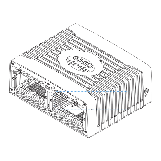
–.00 4 * R 1.00 max Connected Grid Module Slots The router has two module slots to support up to two compatible Cisco Connected Grid modules that add NAN and LAN interfaces to the router. For more information about the Connected Grid modules for this router, see... - Page 22 Router Hardware Description Hardware Features Cable Panel (Back Panel) Features Figure 5 Cable Panel (Back Panel) Features Table 2 Cable Panel (Back Panel) Features Item Feature Description CONFIG Reset button Press for at least 5 seconds to return the router software configuration to the factory default, and power cycle the router.
-
Page 23: Back Panel Leds
Router Hardware Description Hardware Features Table 2 Cable Panel (Back Panel) Features AC power connector Connect the router to the AC power supply (included). For more information, see the AC Power Connector, page Note: The mating connector shipped with the router is a 5-way screw terminal printed circuit board plug connector manufactured by Phoenix Contact (part number 1913604). -
Page 24: Pwr Reset Button
Small Form-Factor Pluggable (SFP) Ports The router features two fiber optical SFP ports that support optional Cisco rugged SFP modules for Gigabit Ethernet connections. The ports are labeled as follows (see Figure 5 on page 22): ... -
Page 25: Ethernet Ports
Router Hardware Description Hardware Features Specifications Specification Description Connector type RJ-45 Copper Interface Full-duplex 10BASE-T, 100BASE-TX, 1000BASE-T Fiber SFP modules: 1000 Mbps 8B/10B coding 100 Mbps 4B/5B coding. Pinouts Connector and Cable Specifications, page Ethernet Ports Figure 5 on page 22 for Ethernet port locations Ethernet Connections The router supports the following Ethernet connection types:... -
Page 26: Combo Ports
Router Hardware Description Hardware Features Specifications Specification Description Connector type RJ-45 Cables Category 5 or higher Interface speed 10BASE-T and 100BASE-TX IEEE standard IEEE 802.3 Pinouts Connector and Cable Specifications, page 95 Gigabit Ethernet (GE) Ports The router features two Gigabit Ethernet (GE) ports for a WAN connection to a primary substation or control center. The ports are labeled as follows: ... -
Page 27: Serial Ports
Router Hardware Description Hardware Features Figure 6 GE Ports and SFP Ports Share Interfaces ETH 2/1 and ETH 2/2 Items Description Gigabit Ethernet Connection Type SFP module ports Fiber optic Gigabit Ethernet ports Copper Serial Ports Figure 5 on page 22 for serial port locations. -
Page 28: Console Port
Router Hardware Description Hardware Features Specifications Specification RS232 RS485 Connector type DB-9 Cable You must order a serial transition cable for the signaling protocol. Signaling Single-ended Differential Max. drivers Max. receivers Operating mode Full duplex Half duplex Full duplex Network topology Point-to-point Multipoint Max. - Page 29 Router Hardware Description Hardware Features AC Power Connector Figure 5 on page 22 for the AC power connection location. The AC power supply connector on the router cable-side (back) panel is the connection to the to AC power terminal block. The router supports single-phase and three-phase AC power input. Note: The mating connector shipped with the router is a 5-way screw terminal printed circuit board plug connector manufactured by Phoenix Contact (part number 1913604).
-
Page 30: Alarm Port
Router Hardware Description Hardware Features Alarm Port Figure 5 on page 22 for the alarm port location. Attach the alarm port to an alarm system to monitor and trigger external alarm events. The router supports two alarm inputs and two alarm outputs. The alarm-trigger setting determines when an alarm is sent to the attached alarm system. -
Page 31: Memory
Space Based Augmentation Systems (SBAS) Related Commands Displaying GPS Current Time and Location for a Cisco CG-OS Router, page 31 Displaying GPS Current Time and Location for a Cisco IOS Router, page 31 Displaying GPS Current Time and Location for a Cisco CG-OS Router Use the commands in this section to see the GPS current time and location. -
Page 32: Wifi Short-Range Access Point
[associations | brief | description | statistics]–Displays the status of the interface as up or down, the five second input and output rate and the number of input and output packets. Additionally, the Cisco CG-OS router displays hardware details such as radio type (802.11N, 2.4 GHz radio), MAC address and MTU setting. -
Page 33: Real-Time Clock (Rtc)
Displaying WiFi Configuration Information for a Cisco IOS Router Note: For a CGR 1120 router using the Cisco IOS operating system, the WiFi interface is identified as ‘Dot11Radio 2/1’. To display WiFi configuration information, enter any or all of the following commands in privileged EXEC or user EXEC mode: ... - Page 34 Router Hardware Description Hardware Features...
-
Page 35: Mounting The Router
Mounting the Router This section describes the safety information, equipment, and procedures required to mount the Cisco 1120 Connected Grid Router on a vertical pole or streetlight. These topics are discussed: Router Mounting Kit, page 35 Prepare to Mount the Router, page 36 ... -
Page 36: Prepare To Mount The Router
Figure 1 Mounting Kit Contents Included Hardware Qty 4 Qty 4 Qty 1 Item Description Qty. Mounting bracket Split lock washer (M8) Nut (M8) Mounting stud (M8) Prepare to Mount the Router Read these topics before mounting the router: Materials and Tools You Supply, page 37 ... -
Page 37: Materials And Tools You Supply
Materials and Tools You Supply You must supply some or all of these items to mount the router on a pole. The items you supply depend on the installation procedure that you use. Item Required for These Procedures #2 Phillips screwdriver Attach the Mounting Bracket to the Router, page ... - Page 38 Use the #2 Phillips screwdriver to remove the four large screws (Item 1, Figure 2 on page 38) from the chassis base. Keep the screws. You will replace them at the end of this procedure to mount the bracket on the chassis. Remove only the screws indicated in Figure 2 on page 38.
- Page 39 Figure 3 Align the Bracket Mounting Holes (2) over the Router Bracket Connectors (3) Replace the screws you removed in Step 2 to secure the mounting bracket to the chassis. Evenly hand-tighten the screws (Item 1 in Figure 4 on page 40), then tighten with the Phillips #2 screwdriver.
-
Page 40: Mount The Router On A Din Rail
Figure 4 Replace and Tighten Screws to Secure Bracket to Router Mount the Router on a DIN Rail The steps in this section assume that your substation or utility box already has a DIN rail installed and ready to support equipment. -
Page 41: Mount The Router On A Wall
Figure 5 Router Mounted on DIN Rail (3) Mount the Router on a Wall The mounting bracket has wall-mount holes that you can use to mount the router directly on a wall. To mount the router on a wall, you must provide the hardware that can be used with the wall material in the installation environment. -
Page 42: Ground The Router
Wall-Mount Height The router should be mounted at a height at which you are able to view the top of the module-side panel and at which the cables are able to be managed without adding stress to the router ports. Wall-Mount Hardware Distance The hardware you provide should be mounted the correct distance apart so that the router wall mount holes (Item 1, Figure 6 on page... - Page 43 Figure 7 Router Grounding Lug Location To ground the router: Use the appropriate crimping tool or pliers to crimp a 6-gauge ground that will attach to the grounding lug on the router exterior. You must provide the wire. Figure 6 on page 42 shows the grounding lug location.
-
Page 45: Before You Begin
Connecting the Router to Power This section describes how to connect the Cisco 1120 Connected Grid Router to AC and DC power source These topics are discussed: Before You Begin, page 45 AC Power Connection Information, page 47 ... -
Page 46: Emc Class A Notices And Warnings (Us And Canada)
Class A Notice for FCC Modifying the equipment without Cisco's authorization may result in the equipment no longer complying with FCC requirements for Class A digital devices. In that event, your right to use the equipment may be limited by FCC regulations, and you may be required to correct any interference to radio or television communications at your own expense. -
Page 47: Ac Power Connection Information
Electrical Wire Color Codes, page 48 Terminal Blocks and Mating Connectors for Power Input Wiring, page 49 Router Power Source Input Terminals The Cisco CGR 1120 Router has two sets of terminals for power input (see Figure 1 on page 48): ... -
Page 48: Electrical Wire Color Codes
Figure 1 Router Power Source Input Terminals Figure 1 on page 48 shows the label for each terminal. Table 1 Power Input Terminals Terminal Type Description AC-Input Power Source Terminals Ground terminal To provide a protected earth ground, terminate either a green/yellow or green wire (region-specific) from the AC power cable on the external screw on the left side of the router. -
Page 49: Terminal Blocks And Mating Connectors For Power Input Wiring
Table 2 AC Power Electrical Wiring Colors by Region Region or Country Standard Ground (Protective Earth) Neutral Line (Phases) European Union IEC 60446 Green-and-yellow Blue Black, brown, gray United States – Green White 120/208/240V: Black, red, blue 277/480V: Brown, orange, yellow Canada –... - Page 50 Figure 2 AC Power Connector Item Description Quantity Captive screws, for connecting terminal block to mating connector on the router Terminal openings for inserting AC-input source wires Screws for tightening wires into terminal openings Figure 3 DC Power Connector Item Description Quantity Terminal openings for inserting DC-input source wires...
-
Page 51: Connect To Ac Power
Figure 4 Terminal Block Mating Connectors Connected to Router Chassis Connect to AC Power This section describes how to make two the following types of AC power connections to the router: Single-phase AC Three-phase AC Note: The AC power connection mating connector shipped with the router is a 5-way screw terminal printed circuit board plug connector manufactured by Phoenix Contact (part number 1913604). -
Page 52: Connect To Dc Power (Optional)
Figure 5 AC Power Connector Wiring 3-Phase AC Power Single-Phase AC Power After the wires are inserted into the connector terminals, use the screwdriver to tighten the connector screw terminals. The screw terminals are shown in Figure 2 on page Connect the AC power connector to the AC power connection on the router as shown in Figure 4 on page Use the screwdriver to tighten the two captive screws on the connector. -
Page 53: Power Cycling The Router
Using a wire-stripping tool to strip both of the wires from the DC-input power source. Expose the wire to the appropriate length for the DC power connector, about 0.25 inches. Insert the wires into the DC power connector terminals described in Figure 1 on page 48 Table 1 on page Note:... - Page 54 Figure 7 Router Power and Reset Buttons Item Button Description CONFIG Reset Press the CONFIG Reset button for at least 5 seconds to return the router software configuration to the factory default, and power cycle the router. Power cycling the router turns the router off, then immediately back on.
-
Page 55: Making Network Connections
Making Network Connections This section describes how to connect network and other connections when installing the Cisco 1120 Connected Grid Router, and includes the procedures for basic router network connections and for optional installation steps. The procedures you follow depend on your network environment and requirements. - Page 56 Figure 1 on page 57 for the Ethernet port locations. One or two Ethernet cables are typically provided with the router. Additional cables and transceivers can be ordered from Cisco. For ordering information, contact your reseller or Cisco customer service.
-
Page 57: Connecting The Sfp Ports
The GE ports (ETH 2/1 and ETH 2/2) have identical labels to the SFP ports because the SFP ports share physical ports with the GE ports. For detailed information about how to use these ports (called combo ports), see Combo Ports, page Warning:... - Page 58 Use only Cisco SFP transceiver modules with the router. Each SFP transceiver module supports the Cisco Quality Identification (ID) feature which allows a Cisco switch or router to identify and validate that the transceiver module is certified and tested by Cisco.
-
Page 59: Verify Ethernet Connection With System Software Cli
For detailed information on connecting the SFP module cables to the network, see Cisco.com for the documentation for your SFP module. Figure 2 SFP Ports SFP ports Verify Ethernet Connection with System Software CLI Note: The show interface command works on routers using the Cisco CG-OS or Cisco IOS operating systems. The example shown is for a router using a CG-OS operating system. -
Page 60: Additional Router Connections
DTR=down RTS=down CTS=down For more information about using the show interface command, see the Cisco 1000 Series Connected Grid Routers Software Configuration Guide. Additional Router Connections This section provides information about making other router cable connections. Follow the procedures in this section based on your network configuration and requirements. -
Page 61: Related Information
Figure 3 Console Port (Item 1) Console port Connecting This section describes how to connect a PC terminal to the console port. When a terminal is connected to the console port, you can connect directly to the router and configure it. You can connect a PC terminal to this port while the router is operating normally. -
Page 62: Connecting The Usb Port
You must provide or purchase separately the correct serial cable. The cable does not ship with the router. Contact your Cisco reseller to purchase the correct cable from Cisco. You can connect a device to this port while the router is operating normally. -
Page 63: Connecting The Alarm Port
The alarm port provides data about fatal or severe errors that can cause the system software to crash. The alarm port is connected to a normally closed solid state relay. Cisco CG-OS writes to a hardware port and the relay contact opens. -
Page 64: Sd Flash Memory Module Card
If you use an alarm system on your network, connect the alarm port to an alarm system with an alarm cable that you provide. Related Information Router Hardware Description, page 13 includes detailed information about this port, including: Alarm input and output ... -
Page 65: Installing Modules And Antennas
SD Card Slot SD card slot Installing Modules and Antennas The router supports up to two Cisco Connected Grid modules. Each module requires one or two antennas, which are installed on the module or near the router. Related Information ... -
Page 67: Installing And Removing Modules
This section describes the installation information for the Cisco Connected Grid modules supported by the Cisco 1120 Connected Grid Router. The router supports up to two Cisco Connected Grid modules to enable network connections from the router to field devices, such as smart meters, and from the router to the utility or data management center. -
Page 68: Installation Warning Statements
CLI or CG-DM application. The instructions for removing a module can vary based on the router operating system—Connected Grid operating system (CG-OS) or Cisco IOS operating system. Note: The CGR 1120 router supports online insertion and removal (OIR) of modules. To install a module by OIR, there are two options: ... - Page 69 Terminal Session, page Power down the slot (number 3 or 4) by issuing the appropriate command at the (CLI): — For a router using Cisco CG-OS, use the following command: router(config)# poweroff module slot Note: To power down a module slot use the poweroff module slot command in global configuration mode. The slot is the slot number of the module (3 or 4).
-
Page 70: Removing A Module
For CG-DM instructions on how to install a module: — If the router is using Cisco CG-OS, see the “Add a Module” section of the “Using the Device Manager” chapter of the Cisco Connected Grid Device Manager Installation and User Guide on Cisco.com. - Page 71 Cisco Connected Grid Device Manager Installation and User Guide on Cisco.com. — If the router is using Cisco IOS, see the “Removing a Module” section of the “Using the Device Manager” chapter of the Cisco Connected Grid Device Manager Installation and User Guide (Cisco IOS) on Cisco.com.
-
Page 72: Where To Find Additional Module Information
Cellular 3G CDMA (Cisco IOS) Installation and Configuration Guide (Cisco IOS) Cisco Connected Grid Modules for CGR 1000 Series – Cisco Connected Grid 3G GSM Module for CGR 1000 Series Cellular 3G GSM (Cisco IOS) Installation and Configuration Guide (Cisco IOS) Cisco Connected Grid Modules for CGR 1000 Series –... -
Page 73: Router Antennas Overview
About Connected Grid Antennas This section describes the Cisco 1120 Connected Grid Router antennas, and describes how to find product and installation information for all Cisco Connected Grid antennas. This chapter includes these sections: Router Antennas Overview, page 73 ... -
Page 74: Gps Antenna
If the antenna is mounted outside, the antenna assembly must be grounded either at the bracket or at the external building point where the cabling enters the building. This is critical because if it’s not grounded, the CGR 1120 chassis would be isolated on the antenna card very close to AC isolation requirements. Also see Statement 1052 below. -
Page 75: Wifi Antenna
For example, a technician can check the status of the router from outside the substation or utility cabinet by connecting to the router over the WiFi link. WiFi Antenna Information The Cisco order number of the WiFi antenna kit is: ANT-4G-DP-IN-TNC. The WiFi antenna is a field-replaceable component. ... -
Page 76: Connected Grid Module Antennas
Connected Grid modules installed in the router. The router supports up to two Cisco Connected Grid modules. Each module requires one antenna or two antennas (one main antenna and one diversity antenna). The total number of antennas installed with the router depends on: ... -
Page 77: Antenna Specifications
Antenna Specifications This section contains specifications for the fixed antennas that ship with the router. For all technical details and specification for these and other Cisco Connected Grid antennas, see the Cisco Connected Grid antenna documentation on Cisco.com at: www.cisco.com/go/cg-modules... -
Page 78: Wifi Antenna Specifications
WiFi Antenna Specifications Specification Value Dimensions 9.0 x 1.2 x 0.6 inches (229 x 30.5 x 15 mm) Weight 1.73 ounces (49 grams) Connector TNC male Frequency 698 to 806 MHz 824 to 894 MHz 880 to 960 MHz 1710 to 1880 MHz 1850 to 1990 MHz 1920 to 2170MHz 2100 to 2500 MHz... -
Page 79: Sd Card Overview
Using the SD Flash Memory Module This section describes the Secure Digital (SD) flash memory module (or SD card) that is used with the Cisco 1120 Connected Grid Router, and includes instructions for installing and removing the SD card. These topics are discussed: ... -
Page 80: Sd Card Status
Sharing SD Cards Across Systems The card cannot be used to configure or operate any system other than the system with which is it shipped. Supported SD Cards Table 1 on page 80 lists the SD cards that can be used with the router. Table 1 Supported SD Flash Memory Modules Size... -
Page 81: Accessing The Sd Card
Figure 2 SD LED – SD Flash Memory Module LED States Label Color and State Description Description Green solid SD flash card is installed and operating normally. SD flash card status Note: If the SD Card is removed, the SD flash memory module LED remains green solid until the router is rebooted. -
Page 82: Safety Warnings
You must replace a faulty or damaged SD card. The topics in this section include: Safety Warnings, page 82 Preventing Electrostatic Discharge Damage, page 82 Tools You Supply, page 82 Inserting and Removing the SD Card, page 82 Safety Warnings Before performing any of the tasks in this section, read the safety warnings in Installation Safety and Site Preparation,... -
Page 83: Securing The Sd Card With A Password
Securing the SD Card with a Password Note: The CLI cited in this section work for both the CG-OS and Cisco IOS operating systems. The SD card contents can be secured with a password. Once a password is set, the password must be supplied before data can be accessed on the SD card. -
Page 84: Related Commands
Related Commands Note: The commands in this section work on routers using the Cisco CG-OS or Cisco IOS operating systems. copy running-config startup-config, page 84 sd-card password, page 84 no sd-card password, page 84 show sd-card password status, page 84... -
Page 85: Rear Panel Led Locations
Router LED Locations and States View the Cisco 1120 Connected Grid Router LEDs to determine the overall state of the system and to verify the status of specific connections, ports, and system components. In addition to viewing the LEDs on the router hardware, you can use the router command line interface as described in Related Commands, page 90 to check the system status LED state from remote locations. -
Page 86: Power Supply Led
Figure 1 Cable Panel (Rear Panel) LEDs Power Supply Power Supply LED The power status LED indicates the power status of the router. Table 1 Power Supply LED LED Label Color Description Location Drvr AC/DC Power Supply Green/Red Off: PSU no present PSU and wiring side Green: DC output is OK Red: DC output failed, but AC/DC input is good... -
Page 87: Act Led-System Activity
ACT LED—System Activity The system activity (ACT) LED indicates the state of the router CPU. Table 3 ACT LED LED Label Color and State Description Green blinking The router CPU is operating normally. Green solid The router CPU is not operating, or is not operating normally. The router CPU is not operating. -
Page 88: Console Led-Console Port Status
CONSOLE LED—Console Port Status Table 6 CONSOLE LED LED Label Color and State Description CONSOLE Green Active console connection to the router No console connection ALM LEDS—Alarm Port Status The router has five alarm port LEDs. Table 7 ALM LEDs LED Label Color and Description... -
Page 89: Sd Card Led Location
Table 8 SFP LEDs LED Label Color and State Description Green, 2 blinks/pause 100 MB/s link speed on the corresponding SFP port Green, 3 blink/pause 1000 MB/s link speed No link established Green SFP is installed in the port and the link is active Amber SFP is installed but there is an error condition Green blinking, then off... -
Page 90: Sd Led-Sd Card Status
Figure 2 SD Card LED (Item 1) SD LED—SD Card Status Table 11 SD LED Label Color and State Description Green SD flash card installed and operating normally Note: If the SD Card is removed, the SD flash memory module LED remains green solid until the router is rebooted. - Page 91 This example shows the command output: CGR1120> show led System LED: green, solid Summary of LED status provider: Client State ------------------------------------------- cellular 3/1 | Blinking --- end of list --- CGR-1120>...
- Page 93 Starting a Router Terminal Session This section describes how to start a terminal session with the Cisco 1120 Connected Grid Router using the console port. Start a terminal session with the router when you are at the router installation location and want to administer the router with a direct connection using the command-line interface (CLI) software.
-
Page 94: Connecting To The Console Port With Microsoft Windows
Connecting to the Console Port with Microsoft Windows To connect to the router console port using Microsoft Windows: Start a terminal emulator application, such as Windows HyperTerminal (included with some versions of Windows OS) or PuTTY: www.putty.org Configure the terminal emulation software with the parameters described in About the Console Port, page Connect to the router. -
Page 95: Connector And Cable Specifications
Connector and Cable Specifications This appendix includes specifications for the Cisco 1120 Connected Grid Router connectors, adapters, and compatible cables, and is organized into the following sections: Connector Specifications, page 95 Cable and Adapter Specifications, page 98 Connector Specifications ... -
Page 96: Console Port
Console Port For detailed information about the console port, see Router Hardware Description, page Table 2 Console/Auxiliary Port Specification Signal Name Signal Description Output Output Output – – Input DSR/DCD Input Input Combo Ports For detailed information about the combination ports, see Router Hardware Description, page Copper Interface—Combination Port (SFP and GE Ethernet) Table 3... -
Page 97: Serial Port
Table 4 SFP Port Specification Signal Name Input/Output Signal Description VeeT – TxFault Output Connects to GPIO TxDisable Input Driven from GPIO MOD-DEF(2) Bidir Bidirectional. Connects to I2C data MOD-DEF(1) Input Connects to I2C Clock MOD-DEF(0) Output Grounded in SFP, indicates SFP is present Rate Select –... -
Page 98: Cable And Adapter Specifications
Table 5 Serial Port Specification (continued) RS-232 Signal Description (Abbreviation) Clear to send (CTS) <— —> —> Request to send (RTS) <— The RS232 pinouts use the EIA-561 standard. Power Connectors For detailed information about the router power supply terminal connectors (AC and DC input terminals), see Router Hardware Description, page Cable and Adapter Specifications...
Need help?
Do you have a question about the 1120 and is the answer not in the manual?
Questions and answers