Table of Contents
Advertisement
SERVICE MANUAL
SERVICE MANUAL
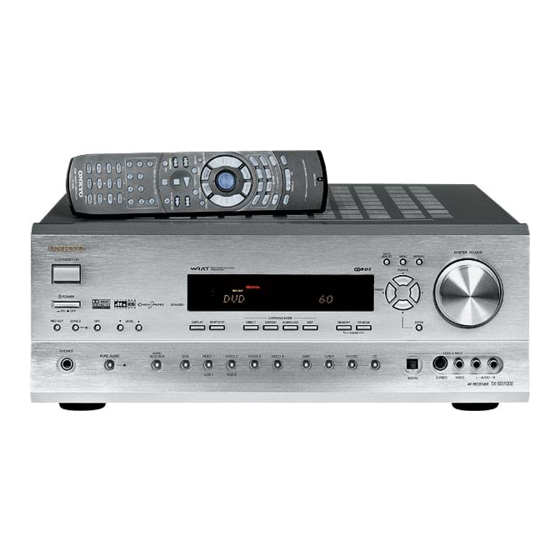
AV RECEIVER
TX-SR700/E
MODEL
Black, Golden and Silver models
BMDD
BMPP,BMPA,SMPP,GMPA
BMWT,GMWT,GMWR
GMGK
SAFETY-RELATED COMPONENT
WARNING!!
COMPONENTS IDENTIFIED BY MARK
SCHEMATIC DIAGRAM AND IN THE PARTS LIST ARE
CRITICAL FOR RISK OF FIRE AND ELECTRIC SHOCK.
REPLACE THESE COMPONENTS WITH ONKYO
PARTS WHOSE PART NUMBERS APPEAR AS SHOWN
IN THIS MANUAL.
MAKE LEAKAGE-CURRENT OR RESISTANCE
MEASUREMENTS TO DETERMINE THAT EXPOSED
PARTS ARE ACCEPTABLY INSULATED FROM THE
SUPPLY CIRCUIT BEFORE RETURNING THE
APPLIANCE TO THE CUSTOMER.
Page 1
120V AC, 60Hz
230~240V AC, 50Hz
120/220~230V AC, 50/60Hz
220V AC, 50Hz
ON THE
TX-SR700/E
Ref. No. 3731
062002
RC-482M
Advertisement
Table of Contents

Related Manuals for Onkyo TX-SR700/E


Summary of Contents for Onkyo TX-SR700/E
- Page 1 COMPONENTS IDENTIFIED BY MARK ON THE SCHEMATIC DIAGRAM AND IN THE PARTS LIST ARE CRITICAL FOR RISK OF FIRE AND ELECTRIC SHOCK. REPLACE THESE COMPONENTS WITH ONKYO PARTS WHOSE PART NUMBERS APPEAR AS SHOWN IN THIS MANUAL. MAKE LEAKAGE-CURRENT OR RESISTANCE...
-
Page 2: Specifications
TX-SR700/E SPECIFICATIONS AMPLIFIER SECTION 50 dB quieting sensitivity Mono: 17.2 dBf, 2.0 µV (75 ohm ) Continuous average power output (FTC) Stereo: 37.2 dBf, 20 µV (75 ohm ) All channels: 100 W per channel min. RMS at 8 ohm, Capture ratio: 2.0 dB... -
Page 3: Service Procedures
TX-SR700/E SERVICE PROCEDURES 1. Replacing the fuses 5.Setting the voltage selector (Worldwide models only) This symbol located near the fuses indicates that the fuse used is fast operating type. For continued protection against Worldwide models are equipped with a voltage selector to conform fire hazard, replace with same type fuse. -
Page 4: Exploded View
TX-SR700/E EXPLODED VIEW P901 P101 P2602 F6902 F6901 F903 P7501 Q6050 Q6060 F901 F902 Q6056 P7502 Q6066 P6931 T901 F9501 Page 4... -
Page 5: Exploded View Parts List
TX-SR700/E EXPLODED VIEW-PARTS LIST 2 NOTE: THE COMPONENTS IDENTIFIED BY MARK ! ARE CRITICAL FOR RISK OF FIRE AND ELECTRIC SHOCK. REPLACE ONLY WITH PART NUMBER SPECIFIED. REF.NO. PART NO. DESCRIPTION REF.NO. PART NO. DESCRIPTION T901 2301587 NPT-1439D,Power transformer <D>... - Page 6 TX-SR700/E EXPLODED VIEW-PARTS LIST 1 REF.NO. PART NO. DESCRIPTION REF.NO. PART NO. DESCRIPTION CAUTION: Replacement for transistor of mark *, if necessary 27111271B Front bracket <B> 28141494 Cushion must be made from the same beta group (h ) as the original type.
-
Page 7: Block Diagram
TX-SR700/E BLOCK DIAGRAM DIGITAL AUDIO INPUT FRONT DIGITAL AUDIO OUTPUT OPTICAL OPTICAL COAXIAL +2.5V FLASH ROM 4M-BIT MX23L4000 +3.3V 12.288MHZ OPTICAL 1 COAXIAL MEMORY OPTICAL 2 (DD-EX) 50KLPF (AC-3,DTS) AK4586 (DTS-ES) (1/3) (PLII,NEO:6) CS493292 DAUX 50KLPF 96/24 192/24 FM/AM AK4586... - Page 8 TX-SR700/E BLOCK DIAGRAM MULTICHANNEL INPUT / DVD IN HEAD PHONE DVD/ R DVD/ L HPEN ZONE 2 BD3811K1 (2/2) MASTER VOLUME Power Amplifier BASS/TREBLE MUTE BOOST SW->L +29dB BYPASS BASS/TREBLE MUTE SW->R +29dB MCSL BYPASS MUTE PREOUT FRONT SPEAKERS +29dB...
-
Page 9: Printed Circuit Board View
TX-SR700/E PRINTED CIRCUIT BOARD VIEW 9 Video section 2 P2060 P241 P2060 COMPONENT2 COMPONENT1 COMPONENT P241 Soldering side RL241 Component side J2064 J2061 J2065 RL242 J2062 P242A P243A Component video terminal PC board P105A J2018 P107A P106A R2079 J2013 C2245... - Page 10 TX-SR700/E PRINTED CIRCUIT BOARD VIEW 8 Video terminal PC board Video section 1 U201 U202 U203 P208 P203 P202 P201 P2004 P206 P206 U203 U201 U202 P208 L242 Q2033 J205 P202 J210 P203 P201 COAX Q2033 J201 RX-2 RX-1 L242...
- Page 11 TX-SR700/E PRINTED CIRCUIT BOARD VIEW 7 Power supply and output sections C9591 2.5A/125V P7502B F9501A F9501B FAC1 HPL1 FAC2 F9501 HPR1 R9593 P995B 25137477 J9509 NCPS-7477 HPR1 J9506 J9511 JL9501A HPL1 Secondary circuit PC board NCETC-7478 25137478 P6810 P6811 J12A...
- Page 12 TX-SR700/E PRINTED CIRCUIT BOARD VIEW 5-1 Power supply and output sections NCETC-7476 25137476 JL6804C J6712 J6711 JL6810A J6730 J6710 JL6805C J6739 J6752 JL6803C J6731 J6720 J6721 J6708 J6740 J6748 J6736 J6718 R6860 J6709 J6724 J6719 L6851 L6850 J6707 L6852 J6725...
- Page 13 TX-SR700/E PRINTED CIRCUIT BOARD VIEW 5-2 Power amplifier section 3 J6127 J6082 J6016 Q6012 Q6011 Q6010 Q6052 Q6061 Q6051 Q6062 Q6060 Q6050 R6092 R6521 R6091 R6090 R6511 J6034 R6510 J6134 J6122 J6099 J6081 J6076 J6037 J6036 J6123 J6077 J6014 J6102...
- Page 14 TX-SR700/E PRINTED CIRCUIT BOARD VIEW 5-1 Power amplifier section 2 J6192 J6174 J6147 J6204 R6512 Q6015 Q6014 Q6013 Q6054 Q6053 Q6065 Q6055 Q6064 Q6063 Q6062 R6094 R6093 R6522 R6513 J6145 R6095 J6199 J6188 J6180 J6173 J6168 J6159 J6155 J6146 J6189...
- Page 15 TX-SR700/E PRINTED CIRCUIT BOARD VIEW 4-1 Q5035 C5005 Power amplifier section 1 R5195 R5005 C5015 R5185 C5115 R5165 R5015 R5135 R5025 J5052 C5095 C5045 J5053 R5105 Q5055 R5085 R5075 Q5015 R5175 R5155 R5145 J5091 J5090 C5004 R5194 R5004 C5014 R5184...
-
Page 16: Front Panel Section
TX-SR700/E PRINTED CIRCUIT BOARD VIEW 3 Front panel section P209B P2501B NCVD-7467 25137467 P2503 JL7502B P7705 HPL2 HPR2 HPDET P2505 P2503 25137463 NCETC-7463 Component side Component side C7702 L7703 R2505 R2503 R2504 C2502 C2501 C2503 L7704 HPL2 C2504 C7704 HPR2... -
Page 17: Dsp Section
TX-SR700/E PRINTED CIRCUIT BOARD VIEW 2-4 DSP section Q9503 R9503 R729 P2601A R728 R727 R726 D9509 C718 C717 R707 C716 C707 L703 C713 R708 R723 R709 L701 C714 L706 R710 C715 R711 C729 Q705 C709 L702 C705 Q705 Q702 Q704... - Page 18 TX-SR700/E PRINTED CIRCUIT BOARD VIEW 2-3 DSP section R320 C320 R321 C321 P305 R318 C318 R319 C319 C326 R316 R317 R314 R854 R848 R838 R828 C314 R855 R849 R839 R829 R315 R852 R846 R836 R826 R350 C315 R853 R847 R837...
- Page 19 TX-SR700/E PRINTED CIRCUIT BOARD VIEW 2-2 DSP section Q9503 R9503 R729 P2601A R728 R727 R726 D9509 C718 C717 R707 C716 C707 L703 C713 R708 R723 R709 L701 C714 L706 R710 C715 R711 C729 Q705 C709 L702 C705 Q705 Q702 Q704...
- Page 20 TX-SR700/E PRINTED CIRCUIT BOARD VIEW 2-1 DSP section R320 C320 R321 C321 P305 R318 C318 R319 C319 C326 R316 R317 R314 R854 R848 R838 R828 C314 R855 R849 R839 R829 R315 R852 R846 R836 R826 R350 C315 R853 R847 R837...
- Page 21 TX-SR700/E PRINTED CIRCUIT BOARD VIEW FROM SOLDERING SIDE 1-2 P7502A J7525 NCDIS-7461 J7512 25137461B STANDBY S7641 C7540 JL7501B NCSW-7462 25137462 RL7701 C7521 C7524 J7523 S7501 STANBY D7581 S7501 J7522 Component side Volume PC ZONE2 D7583 SPK-B LEVEL-UP LEVEL-DOWN ZONE2 board...
- Page 22 TX-SR700/E PRINTED CIRCUIT BOARD VIEW FROM SOLDERING SIDE 1-1 P7504 AUDIO RETURN MENU ADJUST P7501A J7551 J7549 J7545 R7591 R7592 R7593 S7613 S7612 S7611 Q7501 TUNING-UP S7614 Q7501 J7558 PRESET U7501 J7537 J7538 PRESET-DOWN J7523 S7615 S7616 J7533 TUNING-DOWN S7617...
-
Page 23: Schematic Diagram
TX-SR700/E SCHEMATIC DIAGRAM 1-1 Display section NADIS-7461 Q7501 HNA-16MM39T P46/FIP38 P47/FIP39 FIP18 62 61:FIP19 P50/FIP40 FIP17 63 P51/FIP41 FIP16 64 P52/FIP42 FIP15 65 P53/FIP43 FIP14 66 P54/FIP44 FIP13 67 P55/FIP45 FIP12 68 Q7502 P56/FIP46 FIP11 69 P57/FIP47 FIP10 70 UPD780233GC... - Page 24 TX-SR700/E SCHEMATIC DIAGRAM 1-2 Display section TO NAPS-7477 (SCH.-6) P7502A AC6V AC6V Except D C7505 473Z HPDET HPR2 RL7701 HPL2 D7702 1SS352 OR 1SS355 D7506 D7701 1SS352 OR 1SS355 Q7701 C7540 1SS352 KRC102S 220/6.3 OR 1SS355 D7507 1SS352 OR 1SS355...
- Page 25 TX-SR700/E SCHEMATIC DIAGRAM 2-1 DSP section 1 < S C H . - 3 > P 1 0 6 B < S C H . - 9 > < S C H . - 9 > F R O N T V I D E O - 4 I N...
- Page 26 TX-SR700/E SCHEMATIC DIAGRAM 2-2 DSP section 2 N J M 4 5 6 5 M I N 2 S E L 1 2 V I D E O - 1 I N 1 0 K R 3 5 0 R 3 5 2...
- Page 27 TX-SR700/E SCHEMATIC DIAGRAM 2-3 DSP section 3 < S C H . - 9 > T O T U N E R P A C K P 1 0 1 D 9 5 0 1 - 9 5 0 3 :...
-
Page 28: Dsp Section
TX-SR700/E SCHEMATIC DIAGRAM 2-4 DSP section 4 D I R I N T 0 R 7 0 5 9 A R E A 1 S P C S P 4 1 / A D 1 R 7 0 3 8... - Page 29 TX-SR700/E SCHEMATIC DIAGRAM 3 Front panel section N A V D - 7 4 6 7 V 4 C G N D V 4 Y G N D V - 4 R 2 5 0 1 V 4 - L...
-
Page 30: Power Amplifier Section
TX-SR700/E SCHEMATIC DIAGRAM 4-1 Power amplifier section 1 N A A F - 7 4 8 3 T O N A D G ( P A R T - 4 P 4 0 4 C ( P 4 0 4 D ) R 5 1 6 3 [ 5 5 . - Page 31 TX-SR700/E SCHEMATIC DIAGRAM 4-2 Power amplifier section 2 N A A F - 7 4 8 3 T O N A A F - 7 4 8 3 T O N A D G - 7 4 6 0 T O N A D G - 7 4 6 0 ( S C H .
- Page 32 TX-SR700/E SCHEMATIC DIAGRAM 5-1 Power amplifier section 3 N A A F - 7 4 7 4 [ 5 5 . 5 V ] Q 6 0 3 3 R 6 1 6 3 R 6 0 8 3 3 3 K...
- Page 33 TX-SR700/E SCHEMATIC DIAGRAM 5-2 Power amplifier section4 [ 5 5 . 5 V ] Q 6 0 3 0 R 6 1 6 0 N A A F - 7 4 7 4 R 6 0 8 0 3 3 K...
- Page 34 TX-SR700/E SCHEMATIC DIAGRAM 6 Output terminal section N A E T C - 7 4 0 6 P 6 8 0 3 L 6 8 5 0 S 1 . 3 C C 6 6 5 0 1 0 3 J...
-
Page 35: Power Supply Section
TX-SR700/E SCHEMATIC DIAGRAM 7 Power supply section P / G / W / J T Y P E O N L Y C 9 2 2 N A P S - 7 4 8 4 T Y P E N A S W - 7 4 8 7... - Page 36 TX-SR700/E SCHEMATIC DIAGRAM 9 Connector and Equlaizer amplifier sections 4 7 / 5 0 N A A F - 7 4 7 3 < D > : 1 2 0 V m o d e l C 2 0 7 4 <...
- Page 37 TX-SR700/E SCHEMATIC DIAGRAM 8 Video section N A V D - 7 4 6 4 R 2 4 3 C 2 5 1 1 0 4 Z R 2 5 1 0 0 0 J R 2 0 5 4...
- Page 38 TX-SR700/E PC BOARD CONNECTION DIAGRAM JL6801A JL6805C JL6804C JL6803C NASW-7487 POWER SWITCH PC BOARD NAETC-7476 PCB 25 PCB 6 SPEAKER TERMINAL PC BOARD (Except 120V NAETC-7476 model) P6804 Note: PCB XX: PC board view P6803 S902 E921 P911 P6840 JL6805A...
- Page 39 TX-SR700/E PC BOARD CONNECTION DIAGRAM NAETC-7478 PRE. OUTPUT TERMINAL PC BOARD : Flat cable PCB 7 : Jumper Wire : Socket : PC board to PC board P404C U203 P201 P206 U201 P202 P2004 P208 P203 NAETC-7486 U202 CONNECTOR NAVD-7464...
- Page 40 TX-SR700/E PC BOARD-CONNECTION VIEW H E A D P H O N V O L U M E N A E T C - 7 4 6 3 N A S W - 7 4 6 2 ( S C H . - 3 ) ( S C H .
- Page 41 TX-SR700/E PC BOARD-CONNECTION VIEW J L 6 9 5 1 B J L 6 9 5 2 B H E A D P H O N E P O W E R S W N A E T C - 7 4 6 3 P R I M A R Y ( S C H .
-
Page 42: Printed Circuit Board-Parts List
TX-SR700/E Note: PRINTED CIRCUIT BOARD-PARTS LIST 1 <P>: Europpean model only <D>: 120V model only <O>: Other models except 120V model MAIN CIRCUIT PC BOARD (NADG-7460-1N/1O/1P/1Q) CIRCUIT NO. PART NO. DESCRIPTION CIRCUIT NO. PART NO. DESCRIPTION Oscillators X181 3010345 or... - Page 43 TX-SR700/E PRINTED CIRCUIT BOARD-PARTS LIST 2 CIRCUIT NO. PART NO. DESCRIPTION CIRCUIT NO. PART NO. DESCRIPTION Capacitors Transistors C9511~C9514 394562217 220uF,35V,Elect. Q7503 2216175R2 or KTC3875-GR or C9515 394544727 4700uF,16V,Elect. 2213145R2 2SC2712-GR C9516 394674717 470uF,63V,Elect. Q7504 2216230R2 or KRA103S or C9520 394632217 220uF,10V,Elect.
- Page 44 TX-SR700/E PRINTED CIRCUIT BOARD-PARTS LIST 3 NOTE: <O>: Other models except 120V model HEADPHONE TERMINAL PC BOARD (NAETC-7463-1N/1O) CIRCUIT NO. PART NO. DESCRIPTION CIRCUIT NO. PART NO. DESCRIPTION Coils Coils L201 231237M022R2 NCH-1471 L7701 233454M022S NCH-1452 022M L2011~L2014 231237K022R2 NCH-1471...
- Page 45 TX-SR700/E CAUTION: Replacement for transistor of mark *, if necessary PRINTED CIRCUIT BOARD-PARTS LIST 4 must be made from the same beta group (h ) as the original type. CIRCUIT NO. PART NO. DESCRIPTION CIRCUIT NO. PART NO. DESCRIPTION Relays...
- Page 46 TX-SR700/E PRINTED CIRCUIT BOARD-PARTS LIST 5 CIRCUIT NO. PART NO. DESCRIPTION CIRCUIT NO. PART NO. DESCRIPTION Resistors Terminals R6040~R6045 5210258 N06HR1KBC,Trimming P6803 25060328 NTM-8PDMN259 <D> R6070~R6075 415471214 120ohm+/-5%,1/4W,NF carbon 25060329 NTM-8PDMN260 <O> R6080~R6085 415470224 2.2ohm+/-5%,1/4W,NF carbon P6804 25060326 NTM-8PDMN257 <D>...
- Page 47 TX-SR700/E CAUTION: Replacement for transistor of mark *, if necessary PRINTED CIRCUIT BOARD-PARTS LIST 6 must be made from the same beta group (h ) as the original type. PRIMARY CIRCUIT PC BOARD (NAPS-7484-1N/1O/1P/1Q/1R/1U) DRIVER CIRCUIT PC BOARD (NAAF-7483-1N/1O) CIRCUIT NO.
-
Page 48: Main Microprocessor
TX-SR700/E MAIN MICROPROCESSOR Connection diagram TUNER PACK FRONT/CENTER/SURROUND SURROUND CH. BACK/SUBWOOFER CH. RL901 PREOUT PREOUT Q321 MUTE GATE SWITCH Q 9 2 1 P O W E R R E L A Y Q2203,4,2257,8 Q2208 Q9504 ZONE 2 OUTPUT GATE... - Page 49 TX-SR700/E MAIN MICROPROCESSOR Connection diagram M O N I T O R R 2 0 5 4 Q 2 5 1 P 2 0 1 S S 1 M O N I T O R S S 2 Q 2 0 1...
- Page 50 TX-SR700/E SUB-MICROPROCESSOR CONNECTION DIAGRAM Q7501 FL TUBE HNA-16MM39T D7584 PURE AUDIO IND. Q7582 D7583 ZONE 2 IND. Q7583 FIP19 P46/FIP38 40 FIP18 P47/FIP39 39 P50/FIP40 38 FIP17 FIP16 P51/FIP41 37 FIP15 P52/FIP42 36 FIP14 P53/FIP43 35 FIP13 P54/FIP44 34 FIP12...
-
Page 51: Main Microprocessor-Terminal Descriptions
TX-SR700/E MAIN MICROPROCESSOR-TERMINAL DESCRIPTIONS Function I/O Act Description Function I/O Act Description OSDDA Serial data signal output pin to OSD IC. Address 15 output pin to Boot ROM. OSDCL O CLK Serial clock signal output pin to OSD IC. Address 16 output pin to Boot ROM. - Page 52 TX-SR700/E TERMINAL DESCRIPTION SUB MICROPROCESSOR Pin No. Symbol I/O Description Pin No. Symbol I/O Description Power supply terminal. Connect to 5V. Segment output terminal of P22. Ground terminal. Segment output terminal of P21. Ceramic oscillator connection terminals for main system.
-
Page 53: Adjustment And Confirmation Procedures
TX-SR700/E ADJUSTMENT AND CONFIRMATION PROCEDURES 1 Idling current adjustment Before Idling adjustment, turn the trimming resistors R6040 to R6045 to counter clockwise. Connect the DC voltmeter to sockets P6080 to P6085. After turn POWER to ON, adjust the trimming resistors R6040, R6041 and R6042 so that the reading of voltmeter becomes 2.5 mV. -
Page 54: Test Mode
TX-SR700/E ADJUSTMENT AND CONFIRMATION PROCEDURES 2 3. Confirmation of Current detection circuit Set the unit to "Test-1-00". Connect the differentiating circuit and apply the 200Hz square signal to MULTI CHANNEL INPUT terminal of each channel. Adjust the attenuator or Volume so that the output level becomes 35V p-p. -
Page 55: Packing Procedures
TX-SR700/E PACKING PROCEDURES Bottom Except 120V model Accessary bag Note: <B>: Black model only <G>: Golden model only <S>: Silver model only <D>: U.S.A. model only <P>: European model only <T>: Asian model only <R>: Chinese model only <A>: Australian model only Put the label 81 between page 2 and page 3 of instruction manual E. - Page 56 Sales & Product Planning Div. : 2-1, Nisshin-cho, Neyagawa-shi, OSAKA 572-8540, JAPAN Tel: 072-831-8111 Fax: 072-833-5222 ONKYO U.S.A. CORPORATION 18 Park Way, Upper Saddle River, N.J. 07458, U.S.A. Tel: 201-785-2600 Fax: 201-785-2650 E-mail: onkyo@onkyousa.com ONKYO EUROPE ELECTRONICS GmbH Liegnitzerstrasse 6,82194 Groebenzell, GERMANY Tel: +49-8142-4401-0 Fax: +49-8142-4401-555 E-mail: info@onkyo.de...
Need help?
Do you have a question about the TX-SR700/E and is the answer not in the manual?
Questions and answers