Sony PEGA-CC5 Service Manual
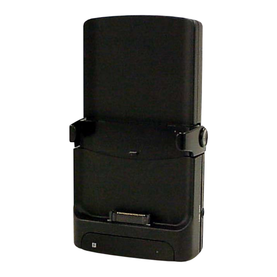
Car cradle
Hide thumbs
Also See for PEGA-CC5:
- Operating instructions manual (84 pages) ,
- Installation/connections (4 pages) ,
- Product manual (3 pages)
Table of Contents
Advertisement
Quick Links
SERVICE MANUAL
Ver 1.1 2003.09
The PEGA-CC5 is composed of the following models.
Cradle unit
PEGA-CC5
DC/DC converter unit
XA-DC5
Remote commander
RM-X136
GPS antenna
VCA-36
ALL
Operating temperature
5 ºC to 35 ºC
(41 ºF to 95 ºF)
Cradle (Body)
Storage temperature
– 40 ºC to 80 ºC
(– 40 ºF to 170 ºF)
Dimensions (W/H/D)
Approx.
78.2
138.5
1
1
(3
/
5
/
8
2
Mass
Approx. 155 g (6 oz)
Connection terminal
DC power adapter
(5.2 V)
CLIÉ I/F
LINE-OUT
GPS Antenna
Connection adapter
Audio Specifications
Frequency response
20 Hz to 20,000 Hz
Built-in Speaker
Maximum power output 1 W
Sony Corporation
9-877-462-02
2003I05-1
e Vehicle Company
C 2003.09
Published by Sony Engineering Corporation
SPECIFICATIONS
Car Battery Adapter
Input
Output
Operating temperature
Dimensions (W/H/D)
Mass
Cord length
37.4 mm
1
1
/
in)
2
GPS Receiver
Location method
Maximum number of tracking satellite
Revive sensitivity
Receive frequency
GPS Antenna
Micro strip planer antenna
FM Transmitter
Transmission range
Frequency response
PEGA-CC5
Power Supply
19 W
Requirement
5.2 V DC, 3,000 mA
5 ºC to 35 ºC
Input
(41 ºF to 95 ºF )
Output
Approx. 112 48 38 mm
1
15
1
Fitting Kit
(4
/
1
/
1
/
in)
2
16
2
Approx. 105 g (3 oz)
Dimensions (W/H/D)
1
Approx. 1.6 m (59
/
in)
8
Mass
Supplied Accessories
All in view method
Car battery adapter
8 satellites
Wireless card remote commander
Less than –130 dBm
1575.42 MHz
GPS antenna
Installation CD-ROM
StreetFinder
Software CD-ROM
Parts for installation and connections
StreetFinder
Software User's Guide
2.4 m to 3.0 m
(8 ft to 10 ft)
95.9 MHz to 101.9 MHz
Design and specifications are subject to change
without notice.
US Model
12 V DC car battery
(negative ground)
19 W
5.2 V DC, 3000 mA
Approx. 40 88 59 mm
5
1
3
(1
/
3
/
2
/
in)
8
2
8
Approx.75 g (3 oz)
XA-DC5
RM-X136
VCA-36
®
3
C
Travel Navigation
®
3
C
Travel Navigation
CAR CRADLE
Advertisement
Table of Contents

Related Manuals for Sony PEGA-CC5


Summary of Contents for Sony PEGA-CC5
- Page 1 PEGA-CC5 SERVICE MANUAL US Model Ver 1.1 2003.09 The PEGA-CC5 is composed of the following models. Cradle unit PEGA-CC5 DC/DC converter unit XA-DC5 Remote commander RM-X136 GPS antenna VCA-36 SPECIFICATIONS Car Battery Adapter Power Supply Operating temperature 5 ºC to 35 ºC...
-
Page 2: Table Of Contents
PEGA-CC5 TABLE OF CONTENTS Notes on chip component replacement • Never reuse a disconnected chip component. • Notice that the minus side of a tantalum capacitor may be dam- SERVICING NOTES ..........3 aged by heat. GENERAL Flexible Circuit Board Repairing Location of Controls ............ -
Page 3: Servicing Notes
PEGA-CC5 SECTION 1 SERVICING NOTES SERVICE POSITION • In checking the CN/MAIN board, prepare extension jig (Part No. J-2502-079-1) and connect jig (Part No. J-2502-079-2). CLIE main board (CN2) CN board (CN902) Connect extension jig (J-2502-079-1) to the main board (CN2) and CN board (CN902). - Page 4 Pentium is registered trademarks of Intel permission of the copyright holder. Note: Corporation. • In no event will SONY be liable for any This equipment has been tested and found to StreetFinder C software © 2003, Rand McNally financial damage or loss of profits, including comply with the limits for a Class B digital device, &...
-
Page 5: General
PEGA-CC5 SECTION 2 This section is extracted from instruction manual. GENERAL Location of controls Front panel A Auto dimmer eye Receptor for the dimmer. B Built-in speaker for the Text- to-voice function (located at the back of the car cradle) •... - Page 6 PEGA-CC5 Wireless card remote commander Refer to the pages listed for details. ® For details about the StreetFinder application, refer to the StreetFinder User’s Guide. For details about replacing the batteries, refer to “Replacing the lithium battery” on page 76.
- Page 7 PEGA-CC5 D < (./m)/, (M/>) I DSPL button buttons • To change the display items for the Press to: Music application. 50 – move the cursor left/right on the • To change the image on Photo/ Car Launcher screen. 31 Screensaver.
- Page 8 Continued on next page GPS Meter This application allows you to view GPS signal reception conditions. Monitor This application displays the playing/receiving information of a Sony car audio when connected to the optional SONY- BUS connection adapter (XA-CC1).
- Page 9 Basic Applications: The basic applications for the car cradle. ® ® When you use the StreetFinder application, install the StreetFinder Audio Monitor: The application for a Sony car audio via the SONY-BUS Travel Navigation Software, too. connection adapter (optional) (page 54). ® For details about installing the StreetFinder Travel Navigation Software, refer to Click Next.
- Page 10 PEGA-CC5 Step 2: Setting up your CLIÉ™ handheld for Step 3: Mounting your CLIÉ™ handheld in the car cradle the car cradle Follow the setup procedure according to your CLIÉ handheld type. To operate applications/functions during in-vehicle mode, mount your CLIÉ...
- Page 11 – The wireless card remote commander of the car cradle is available. respective setting screens. – Car audio operation is available only when the SONY-BUS connection *2 If the application is not usable in normal CLIÉ mode, CLIE Launcher appears.
-
Page 12: Basic Operations
PEGA-CC5 About the caution alarm Basic operations The caution alarm alerts you to not to leave your CLIÉ handheld in the car. After 5 seconds the car cradle is turned off during in-vehicle mode, the caution Operating the touch panel alarm sounds and the screen flashes. - Page 13 Mount your CLIÉ handheld in the car cradle. Monitor 54 This application allows you to view you the Sony The Warning message is displayed. car audio information on the CLIÉ handheld Press any button on the remote commander to cancel the screen.
- Page 14 PEGA-CC5 G ./> icons G ./> icons L Image of sender For details, page 36. If an image of the sender is in refer to Go to the beginning of the Tap . after reading out the header. Address Book, the image is current mail displayed on the screen.
- Page 15 PEGA-CC5 Start time reading out mode Display items The schedule starts to read out automatically when the start time of the schedule is reached. Note Tips If a name consists of many characters, the end is displayed as “…” • This mode starts automatically even if Schedule is not activated.
- Page 16 Listening to music car audio. You can enjoy music in your CLIÉ handheld with your car audio even if it does not have input terminals for other devices, or if the SONY- Complete each setting, refer to the instructions on the BUS connection adapter (optional) is not connected.
- Page 17 PEGA-CC5 Notes Using the SONY-BUS connection adapter • When playback stops, the clock (OFF) display appears on the Sony car audio display. (optional) • The Music screen switches to the Monitor screen depending on the setting (page 73). • LINE OUT is turned off and the built-in FM transmitter is deactivated when the You can operate the Music application with a Sony car audio by connecting SONY-BUS connection adapter is connected.
- Page 18 This application allows you to view GPS signal reception conditions. The Monitor application shows you playing/receiving information (title list of the disc in the CD/MD changer, title list of the FM station memo) on a Sony To start the GPS Meter application car audio.
- Page 19 *6 Available only when an MP3 file is played or CD TEXT disc contains displayable Standard/List information. switch icon* *7 If the disc has been labeled by the Sony car audio using the CUSTOM FILE function, CD/MD unit Disc Memo is displayed accordingly. number* *8 Only for CD TEXT discs with the artist name.
-
Page 20: Other Functions
Configures the settings for the Sound function. (System Sound/Lower audio volume during voice Notes playback/FM Transmitter/Delay time to Sony Car • When you operate Car Setting, detach your CLIÉ handheld from the car cradle. Audio) During in-vehicle mode, Car Setting is not displayed. - Page 21 Setting the Delay time to Sony Car Audio Assigning Applications to Application You can set playback start time to provide time for the Sony car audio to Buttons recognize your CLIÉ handheld. This setting prevents the beginning of a track being cut off.
- Page 22 PEGA-CC5 Setting Miscellaneous Tap the Enable color changing check box. When the check box is checked, the color changes automatically at the specified time set by you. Displaying the Miscellaneous screen Tips Tap the arrow V in the top right-hand corner of the Car •...
- Page 23 The Schedule setting screen is displayed. The screen does not switch to Monitor when “PDA” is selected as a source for a Sony car audio. This setting Tap the check box next to each option to select it. Refer appears only when the Monitor application is installed to the explanation below for details about each option.
-
Page 24: Additional Information
PEGA-CC5 Replacing the lithium battery Additional information Under normal conditions, battery will last approximately 1 year. (The service life may be shorter, depending on the conditions of use.) When the battery becomes weak, the range of the wireless card remote commander becomes This section describes how to solve common problems you may encounter when using shorter. - Page 25 FM transmitter operation FM car audio Car cassette adapter connection Car audio cassette player Car connecting pack CPA-9C (optional) LINE OUT Sony BUS compatible car audio connection Connection adapter XA-CC1 (optional) CONTROL IN BUS AUDIO IN Sony BUS compatible car...
-
Page 26: Connection Diagram
– Direct sunlight (for extended periods of time) • Position the unit at a location that does not • Do not drop the unit. Car Cradle Ready Sony car audio units are; obstruct the operation of passenger-side airbag. • Disconnect the car battery adapter from the •... - Page 27 PEGA-CC5 Mounting support arm Attaching condition and rubber blocks less than 80 mm Dashboard section more than 8 mm parallel fin side fin air vent section more than 6 mm less then 5 mm thick Combination example Mounting example Installing the mounting attachment...
- Page 28 PEGA-CC5 You can also fix the cord of the GPS Connecting the car Detaching your CLIÉ handheld antenna or the car battery adapter to battery adapter the hooks on both sides of the mounting attachment. cord hook A Attaching to the inside of a car Place cord.
-
Page 29: Disassembly
PEGA-CC5 SECTION 3 DISASSEMBLY • This set can be disassembled in the order shown below. 3-3. MAIN BOARD 3-1. DISASSEMBLY FLOW 2 four screws 3-2. FRONT/REAR PANEL ASSY 3-3. MAIN BOARD 3-4. CN BOARD (B2 × 4) 5 main board Note: Follow the disassembly procedure in the numerical order given. -
Page 30: Diagrams
PEGA-CC5 SECTION 4 DIAGRAMS 4-1. BLOCK DIAGRAM – AUDIO Section – R-CH CN901 RS-232C DRIVER FM STEREO TRANSMITTER (CLIE) (FM TRANSMITTER) IC29 IC27 ISOLATION AMP LINE AMP CTS/AOL 22 L_IN 15 ROUT1 RIN1 16 IC15 IC23 MPX-ADJ 5 RF 11... -
Page 31: Block Diagram - Main Section
PEGA-CC5 4-2. BLOCK DIAGRAM – MAIN Section – UNREG_OUT, IO2 – IO6 TXDA, RXDA, INT0 (Page 30) IO0, IO1 UNREG_OUT (Page 30) UNREG_OUT INT1 TXDA INT2 56 RXDA IO5 47 IO6 46 ONBUTN, PON, SYSCLK, SIBDIN, SIBDO, SIBSCK, ONBUTN CS0, CS1, RD, ALE... -
Page 32: Note For Printed Wiring Boards And Schematic Diagrams
PEGA-CC5 4-3. NOTE FOR PRINTED WIRING BOARDS AND SCHEMATIC DIAGRAMS • Waveforms – MAIN Board – Note on Printed Wiring Boards: Note on Schematic Diagram: • X : parts extracted from the component side. • All capacitors are in µF unless otherwise noted. pF: µµF 1 IC13 ql (C32KIN) •... -
Page 33: Schematic Diagram - Main Board (1/5)
PEGA-CC5 4-4. SCHEMATIC DIAGRAM – MAIN Board (1/5) – (1/5) +5V REGULATOR PQ070XZ01Z A5.0V CLIE5.2V A3.3V D3.3V (Page 34) A5V_ON CLIE5.2V C109 R125 5.2V D3.3V DC 5.2V UNREG UNREG (Page 35) MA111 6.3V 6.3V MA111 VOUT XC6201P332MR +3.3V REGULATOR 6.3V... -
Page 34: Schematic Diagram - Main Board (2/5)
PEGA-CC5 Ver 1.1 4-5. SCHEMATIC DIAGRAM – MAIN Board (2/5) – • See page 42 for IC Block Diagrams. (2/5) A5.0V CLIE5.2V A3.3V D3.3V R291 R297 R204 (Page 33) R340 IC29 C190 BUS_GND R232 SP3222ECY-TR R347 22 16V SHDN C152... -
Page 35: Schematic Diagram - Main Board (3/5)
PEGA-CC5 4-6. SCHEMATIC DIAGRAM – MAIN Board (3/5) – • See page 32 for Waveform. • See page 42 for IC Block Diagram. (3/5) A5V_ON (Page 33) CLIE5.2V D3.3V C105 0.01 0.01 0.01 0.01 0.01 0.01 0.01 0.01 0.01 TXDA... -
Page 36: Schematic Diagram – Main Board (4/5)
PEGA-CC5 4-7. SCHEMATIC DIAGRAM – MAIN Board (4/5) – • See page 42 for IC Block Diagrams. (4/5) D3.3V XRESET (Page 33) R333 CAS1 R332 ADDRESS LATCH DATA BUFFER DCKE R330 IC34 IC36 DCS0 R329 TC7MA373FK(EL) TC7MA245FK(EL) 64 Mbit FLASH MEMORY... -
Page 37: Schematic Diagram – Main Board (5/5)
PEGA-CC5 4-8. SCHEMATIC DIAGRAM – MAIN Board (5/5) – • See page 32 for Waveform. (Page 35) (Page 35) (Page 36) (5/5) C107 R214 TTS+ TTS- EQ(L) EQ(R) UART (Page 34) FM/AMP DTC144EUA INVERTER DIMMER IC18 TC75S51F AUTO R197 R196... -
Page 38: Printed Wiring Boards
PEGA-CC5 4-9. PRINTED WIRING BOARDS – MAIN Board (Component Side) – :Uses unleaded solder. FLEXIBLE BOARD LINE OUT TRANSMITTER MAIN BOARD (COMPONENT SIDE) D118 R287 IC34 CN21 C128 C114 C171 R235 C160 (BOOT) R231 R236 R307 C229 IC42 R283 R308... -
Page 39: Main Board (Conductor Side)
PEGA-CC5 Ver 1.1 4-10. PRINTED WIRING BOARD – MAIN Board (Conductor Side) – :Uses unleaded solder. • Semiconductor Location Ref. No. Location F-10 C-10 D111 D122 D123 D111 MAIN BOARD (CONDUCTOR SIDE) R349 R142 1E 2E R145 R119 R155 R150... -
Page 40: Printed Wiring Board - Cn Board
PEGA-CC5 4-11. PRINTED WIRING BOARD – CN Board – :Uses unleaded solder. • Semiconductor Location Ref. No. Location D901 MAIN BOARD D902 D903 (Page 39) CN BOARD (COMPONENT SIDE) D904 D907 D908 D909 R903 D910 R918 R901 Q906 IC901 R916... -
Page 41: Schematic Diagram - Cn Board
PEGA-CC5 4-12. SCHEMATIC DIAGRAM – CN Board – R918 R917 1.5k CN901 Q907 Q906,907 CN902 DTC144EUA (CLIE) B+ SWITCH Q906 C909 R919 2SB1184 R916 DC+B FB903 R906 R905 SGND DC+B 1.5k VBUS DC+B R904 DC+B Q902 DTC144EUA DC+B Q901 C904... - Page 42 PEGA-CC5 • IC Block Diagrams – MAIN Board – IC4 TC74VHC126FT (EL) IC15 BA3121F IC27 BH1415F-E2 IC29 SP3222ECY/TR OUT1 20 SHDN 14 13 10 9 OUT2 19 VCC 18 GND C1– 17 T1OUT C2– 16 R1IN V– T2OUT 15 R1OUT...
- Page 43 PEGA-CC5 IC35, 36 TC7MA245FK (EL) IC40 MBM29LV651UE-90TN-CC 48 A16 20 VCC TIMER for 19 OE 47 VCCQ PROGRAM/ERASE 46 VSS ERASE VOLTAGE 45 DQ15 GENERATOR 44 DQ7 18 B1 43 DQ14 42 DQ6 41 DQ13 PROGRAM VOLTAGE 40 DQ5 GENERATOR...
-
Page 44: Ic Pin Function Description
PEGA-CC5 4-13. IC PIN FUNCTION DESCRIPTION • MAIN BOARD IC9 TC35143DFG (CODEC) Pin No. Pin Name Description 1 to 3 GPIO6 to GPIO8 Not used DIMMER_SW Auto dimmer on/off switch input terminal “L”: AUTO, “H”: OFF ADSYNC Clock signal input for internal A/D converter from the CPU... - Page 45 PEGA-CC5 Pin No. Pin Name Description 49 to 52 GPIO0 to GPIO3 Not used — Not used DVSS1 — Ground terminal System reset signal input from the CPU SSYNC Serial data frame synchronized signal (72 kHz) input from the CPU...
- Page 46 PEGA-CC5 • MAIN BOARD IC13 TMPR3912AU-92 (CPU) Pin No. Pin Name Description — Power supply terminal (+3.3V) Two-way data bus with the SD-RAM — Ground terminal 4, 5 D25, D26 Two-way data bus with the SD-RAM — Power supply terminal (+3.3V) Two-way data bus with the SD-RAM —...
- Page 47 PEGA-CC5 Pin No. Pin Name Description UART serial receive data input from a CLIE UART serial transmit data output to a CLIE INT2 Interrupt request signal input from the ASIC — Not used IRIN UART serial receive data input terminal Not used...
- Page 48 PEGA-CC5 Pin No. Pin Name Description UART serial receive data input from a CLIE — Power supply terminal (+3.3V) POWER LED1 LED drive signal output terminal POWER LED2 LED drive signal output terminal Not used LED7 Not used UART communicating with a CLIE data enable signal output terminal VSS_PLL —...
- Page 49 PEGA-CC5 Pin No. Pin Name Description — Not used Chip select signal output to the ASIC Data read enable signal output to the ASIC — Ground terminal — Power supply terminal (+3.3V) DGRNT Enable signal output of external test logic or bus master Not used...
- Page 50 Muting on/off control signal output to the speaker amplifier CMUTE Muting on/off control signal output for the line output SBUSMUTE Muting on/off control signal output for the SONY bus Not used — Ground terminal CLIE_POWER Power control signal output for a CLIE Not used...
- Page 51 PEGA-CC5 Pin No. Pin Name Description ONBUTN For power on control signal output to the CPU Power on reset signal output to the CPU SYSCLK System clock signal output to the CPU FLRMWE Write enable signal output to the flash memory...
- Page 52 PEGA-CC5 Pin No. Pin Name Description System reset signal input from the reset signal generator “L”: reset NRESET For several hundreds msec. after the power supply rises, “L” is input, then it changes to “H” — Ground terminal SMODE Test terminal Normally fixed at “L”...
-
Page 53: Exploded View
PEGA-CC5 SECTION 5 EXPLODED VIEW NOTE: • -XX and -X mean standardized parts, so they • Items marked “*” are not stocked since they may have some difference from the original are seldom required for routine service. Some one. delay should be anticipated when ordering •... -
Page 54: Electrical Parts List
PEGA-CC5 SECTION 6 ELECTRICAL PARTS LIST MAIN NOTE: • Due to standardization, replacements in the • Items marked “*” are not stocked since they When indicating parts by reference number, please include the board. parts list may be different from the parts speci- are seldom required for routine service. - Page 55 PEGA-CC5 MAIN Ref. No. Part No. Description Remark Ref. No. Part No. Description Remark 1-165-492-21 ELECT 100uF C107 1-125-777-11 CERAMIC CHIP 0.1uF 1-125-777-11 CERAMIC CHIP 0.1uF C109 1-125-777-11 CERAMIC CHIP 0.1uF C114 1-164-943-11 CERAMIC CHIP 0.01uF 1-115-467-11 CERAMIC CHIP 0.22uF...
- Page 56 PEGA-CC5 Ver 1.1 MAIN Ref. No. Part No. Description Remark Ref. No. Part No. Description Remark C190 1-128-004-11 ELECT CHIP 10uF < DIODE > C191 1-125-777-11 CERAMIC CHIP 0.1uF 8-719-404-50 DIODE MA111-TX C192 1-164-943-11 CERAMIC CHIP 0.01uF 8-719-404-50 DIODE MA111-TX...
- Page 57 PEGA-CC5 Ver 1.1 MAIN Ref. No. Part No. Description Remark Ref. No. Part No. Description Remark IC35 6-704-393-01 IC TC7MA245FK (EL) 1-218-977-11 RES-CHIP 100K 1/16W IC36 6-704-393-01 IC TC7MA245FK (EL) 1-218-977-11 RES-CHIP 100K 1/16W IC38 8-759-524-04 IC TC74VHC125FT (EL) 1-218-990-11 SHORT CHIP...
- Page 58 PEGA-CC5 MAIN Ref. No. Part No. Description Remark Ref. No. Part No. Description Remark R130 1-218-933-11 RES-CHIP 1/16W R205 1-218-933-11 RES-CHIP 1/16W R131 1-218-990-11 SHORT CHIP R206 1-220-198-11 RES-CHIP 1/16W R207 1-218-965-11 RES-CHIP 1/16W R132 1-218-933-11 RES-CHIP 1/16W R208 1-218-965-11 RES-CHIP...
- Page 59 PEGA-CC5 Ver 1.1 MAIN Ref. No. Part No. Description Remark Ref. No. Part No. Description Remark R310 1-208-691-11 METAL CHIP 2.2K 0.5% 1/16W R423 1-218-977-11 RES-CHIP 100K 1/16W R311 1-218-977-11 RES-CHIP 100K 1/16W R425 1-218-941-81 RES-CHIP 1/16W R430 1-218-933-11 RES-CHIP...
- Page 60 PEGA-CC5 Ref. No. Part No. Description Remark Ref. No. Part No. Description Remark PARTS FOR INSTALLATION AND CONNECTIONS ************************************** 3-255-939-01 ARM (1), HOLD (S) X-3383-786-1 ARM (2) ASSY, HOLD (L) 3-255-988-01 BRACKET 3-258-235-01 BRACKET (KNOB) HOLDING ARM (S) HOLDING ARM (L) ×...
- Page 61 PEGA-CC5 MEMO...
- Page 62 PEGA-CC5 REVISION HISTORY Clicking the version allows you to jump to the revised page. Also, clicking the version at the upper right on the revised page allows you to jump to the next revised page. Ver. Date Description of Revision 2003.07...
Need help?
Do you have a question about the PEGA-CC5 and is the answer not in the manual?
Questions and answers