Table of Contents
Advertisement
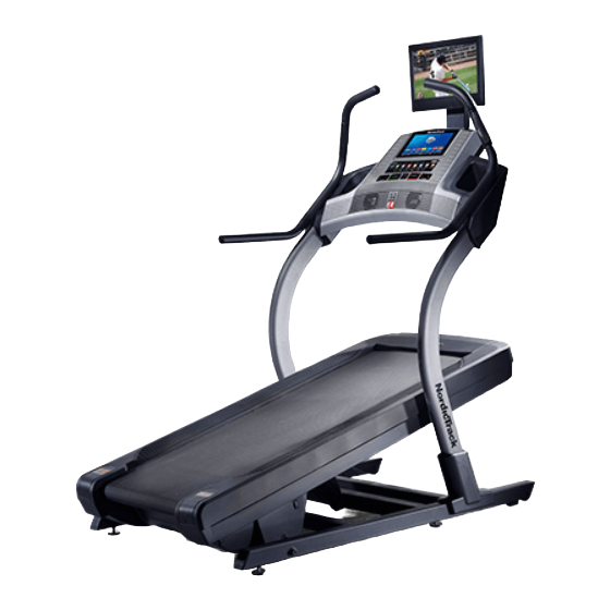
www.nordictrack.com
Model No. NTL29014.1
Serial No.
Write the serial number in the space
above for reference.
ACTIVATE YOUR
WARRANTY
To register your product and
activate your warranty today, go
to www.nordictrackservice.com/
registration.
CUSTOMER CARE
For service at any time, go to
www.nordictrackservice.com.
Or call 1-800-TO-BE-FIT
(1-800-862-3348)
Mon.–Fri. 6 a.m.–6 p.m. MT
Sat. 8 a.m.–12 p.m. MT
Please do not contact the store.
CAUTION
Read all precautions and instruc-
tions in this manual before using
this equipment. Save this manual
for future reference.
Serial
Number
Decal
USER'S MANUAL
Advertisement
Table of Contents
Troubleshooting

Related Manuals for NordicTrack X15i


Summary of Contents for NordicTrack X15i
- Page 1 USER’S MANUAL Model No. NTL29014.1 Serial No. Write the serial number in the space above for reference. Serial Number Decal ACTIVATE YOUR WARRANTY To register your product and activate your warranty today, go to www.nordictrackservice.com/ registration. CUSTOMER CARE For service at any time, go to www.nordictrackservice.com.
-
Page 2: Table Of Contents
Google Inc. The BLUETOOTH ® word mark and logos are registered trademarks of Bluetooth SIG, Inc. and are used under license. Google Maps is a trademark of Google Inc. NORDICTRACK is a registered trademark of ICON Health & Fitness, Inc. -
Page 3: Important Precautions
19. To commercial, rental, or institutional setting. purchase a surge suppressor, see your local NORDICTRACK dealer, call the telephone 5. Keep the incline trainer indoors, away from number on the front cover of this manual, or moisture and dust. - Page 4 19. When a person is walking on the incline 28. Over exercising may result in serious injury trainer, the noise level of the incline trainer or death. If you feel faint, if you become short will increase. of breath, or if you experience pain while exercising, stop immediately and cool down.
- Page 5 34. Upon completion of any service or repairs to when a separate antenna-grounding elec- the incline trainer or the television, ask the trode is used. See NEC Section 810-21 (j) or service technician to perform safety checks your local codes and ordinances. to confirm that the unit is in proper operating condition.
- Page 7 STANDARD SERVICE PLANS...
-
Page 8: Before You Begin
Thank you for selecting the revolutionary reading this manual, please see the front cover of this NORDICTRACK X15I INCLINE TRAINER. The X15I manual. To help us assist you, note the product model ® INCLINE TRAINER offers a selection of features number and serial number before contacting us. -
Page 9: Part Identification Chart
PART IDENTIFICATION CHART Use the drawings below to identify small parts used for assembly. The number in parentheses below each draw- ing is the key number of the part, from the PART LIST near the end of this manual. The number following the key number is the quantity used for assembly. -
Page 10: Assembly
ASSEMBLY • Assembly requires two persons. • To identify small parts, see page 9. • Place all parts in a cleared area and remove the • Assembly requires the following tools: packing materials. Do not dispose of the packing materials until you fi nish all assembly steps. the included hex keys •... - Page 11 3. Remove the four 3/8" x 2 3/4" Screws (22) from the Uprights (83). Save the Screws. 4. Set the Uprights (83) on the Base (74). Make sure that the hole with the Upright Wire (75) is on the right side. Attach the right Upright (83) to the Base (74) with four of the 3/8"...
- Page 12 5. See the inset drawing. Connect the Base Wire (52) to the Upright Wire (75). The connectors should slide together easily and snap into place. If they do not, turn one connector and try again. IF YOU DO NOT CONNECT THE CON- NECTORS PROPERLY, THE CONSOLE MAY BECOME DAMAGED WHEN YOU TURN ON THE POWER.
- Page 13 7. Slide the Right Inside Upright Cover (70) against the lower end of the right Upright (83). Press the Right Outside Upright Cover (71) against the Right Inside Upright Cover until it snaps into place. Make sure that the wires are not pinched.
- Page 14 9. See drawing 9a. Insert the wires and the coaxial cable from the TV (105) through the hole in the TV Bracket (102) as shown. See drawing 9b. Attach the TV Bracket (102) to the TV (105) with the four M4 x 12mm Screws (100) that you removed in step 8.
- Page 15 12. Attach the TV assembly (F) to the console assembly (B) with the four 5/16" x 3/4" Screws (99) that you removed in step 11; start all four Screws, and then tighten them. Be careful not to pinch the wires. Attach the Lower TV Bracket Cover (103) with two #8 x 3/4"...
- Page 16 Before operating the TV, you must connect an antenna or a 75 ohm CATV cable to the 75 ohm terminal, an AV cable to the audio/video input jack, or an HDMI cable to the HDMI input jack. Note: Use a CATV cable to connect to an external source such as a cable box, satellite TV box, VCR, or analog cable.
- Page 17 HOW TO CONNECT A VCR, DVD PLAYER, OR HOW TO CONNECT A DVD OR BLU-RAY PLAYER OTHER DEVICE USING AN AV CABLE OR OTHER DEVICE USING AN HDMI CABLE 1. Connect the three-pronged end of an RCA AV 1. Connect one end of an HDMI cable to your DVD or cable to your VCR, DVD player, or other device.
-
Page 18: The Chest Heart Rate Monitor
THE CHEST HEART RATE MONITOR HOW TO PUT ON THE HEART RATE MONITOR • Store the heart rate monitor in a warm, dry place. Do not store the heart rate monitor in a plastic bag or If the heart rate monitor looks like the one shown other container that may trap moisture. -
Page 19: How To Use The Incline Trainer
HOW TO USE THE INCLINE TRAINER HOW TO CONNECT THE POWER CORD nominal 120-volt circuit capable of carrying 15 or more amps. To avoid overloading the circuit, do Use a Surge Suppressor not plug other electrical devices, except for low- power devices such as cell phone chargers, into Your incline trainer, like other electronic equipment, the surge suppressor or into an outlet on the same... - Page 20 CONSOLE DIAGRAM MAKE YOUR FITNESS GOALS A REALITY WITH FEATURES OF THE CONSOLE IFIT.COM The advanced incline trainer console offers an array of With your new iFit-enabled fitness equipment, you can features designed to make your workouts more effec- use an array of features on iFit.com to make your fit- tive and enjoyable.
- Page 21 HOW TO TURN ON THE POWER HOW TO USE THE TOUCH SCREEN IMPORTANT: If the incline trainer has been The console features a tablet with a full-color touch exposed to cold temperatures, allow it to warm to screen. The following information will help you become room temperature before you turn on the power.
- Page 22 HOW TO SET UP THE CONSOLE The console is now ready for you to begin working out. The following pages explain the various workouts and Before using the incline trainer for the first time, set up other features that the console offers. the console.
- Page 23 HOW TO USE THE MANUAL MODE To stop the walking belt, press the Stop button. To restart the walking belt, press the Start button. 1. Insert the key into the console. 4. Change the incline of the incline trainer as See HOW TO TURN ON THE POWER on page desired.
- Page 24 • The distance that you have walked or run To measure your heart rate, stand on the foot rails and hold the contacts with your palms for • The number of vertical feet you have climbed approximately ten seconds; avoid moving your hands.
- Page 25 HOW TO USE AN ONBOARD WORKOUT At the end of the first segment of the workout, the incline trainer will automatically adjust to the speed 1. Insert the key into the console. and/or incline settings for the next segment. See HOW TO TURN ON THE POWER on The workout will continue in this way until the last page 21.
- Page 26 4. Monitor your progress with the displays. To select a calorie, time, distance, or pace goal, touch the Calories, Time, Distance, or Pace button. See step 5 on page 23. The screen can also Then, touch the increase and decrease buttons on show a profile of the speed and incline settings of the screen to set a calorie, time, distance, or pace the workout.
- Page 27 7. Turn on the fan if desired. 5. Start the workout. See step 7 on page 24. Touch the Start Workout button on the screen to start the workout. A moment after you touch the 8. When you are finished exercising, remove the button, the walking belt will begin to move.
- Page 28 4. Select an iFit workout. 5. Start the workout. To download See step 3 on page 25. an iFit workout in your sched- During some workouts, an audio coach may guide ule, touch the you through your workout. Map, Train, Video, or Lose 6.
- Page 29 HOW TO USE THE EQUIPMENT SETTINGS MODE 6. Select an update time. 1. Select the settings main menu. To select a time for automatic console updates, touch the Update Time button and select the Insert the key into the console desired time.
- Page 30 10. Enable or disable the key. To set the amount of time the console will wait before it automatically resets, touch the Safety Note: This feature may not be enabled on your Screen Timeout button to view a list of times. Then, incline trainer.
- Page 31 HOW TO CHANGE THE AUDIO INPUT HOW TO USE THE MAINTENANCE MODE To select a different audio source, touch the music 1. Select the settings main menu. notes button at the bottom of the screen. Then, choose an audio source from the list. Note: Select Personal TV See step 1 on page 29.
- Page 32 4. Calibrate the incline system of the incline HOW TO USE THE WIRELESS NETWORK MODE trainer. The console features a wireless network mode that Touch the Calibrate Incline button. Then, touch the allows you to set up a wireless network connection. Begin button to calibrate the incline system.
- Page 33 An information box will ask if you want to connect HOW TO USE A TABLET WITH THE CONSOLE to the wireless network. Touch the Connect button to connect to the network or touch the Cancel but- Note: To connect your tablet to the console, you must ton to return to the list of networks.
- Page 34 HOW TO USE THE TABLET HOLDER HOW TO OPERATE THE DIGITAL TV Secure your tablet to the console while you use the You can control the digital TV with the buttons on the incline trainer. Pull the tablet holder (A) upward and console, with the buttons on the top of the digital TV, or place your tablet on the console.
- Page 35 4. Adjust the volume as desired. 3. Set default settings. Press the Vol increase and decrease buttons to Touch the Default Settings button and set a default adjust the volume level. When the buttons are channel and a default volume level for the digital pressed, a graphic will appear on-screen to show TV if desired.
- Page 36 Press the return button ( ) to view the previous HOW TO REPLACE THE BATTERIES IN THE channel. REMOTE CONTROL Press the Menu button to view the main menu or to To replace the batteries, view a previous menu. See this page to page 38 for first locate the battery information about the menu.
- Page 37 2. Adjust the image settings. Select Channel List to view a list of channels saved in the TV memory. Highlight a channel and press The Picture menu offers numerous features for Enter to select the channel. adjusting the TV display. Use the arrow buttons to navigate through the various settings and personal- Select Favorite List to view a list of your favor- ize the image settings.
- Page 38 6. Set up the basic television settings. Select No Signal Power Off to have the TV shut off if no signal is detected for 10 minutes. The Setup menu allows you to adjust the closed caption settings, the language used in the menus, Select No Operation Power Off to have the TV shut or the clock settings.
-
Page 39: How To Move The Incline Trainer
HOW TO MOVE THE INCLINE TRAINER Before moving the incline trainer, insert the key Carefully roll the incline trainer on the wheels to the into the console, raise the incline to the maximum desired location, and then lower it to the level position. incline level, remove the key, and unplug the power CAUTION: To reduce the risk of injury, use extreme cord. -
Page 40: Maintenance And Troubleshooting
MAINTENANCE AND TROUBLESHOOTING MAINTENANCE SYMPTOM: The power turns off during use Regular maintenance is important for optimal perfor- a. Check the power switch (see drawing c at the left). mance and to reduce wear. Inspect and properly tighten If the switch has tripped, wait for five minutes and all parts each time the incline trainer is used. - Page 41 Next, locate c. Your incline trainer features a walking belt coated Top View the Reed with high-performance lubricant. IMPORTANT: Switch (67) Never apply silicone spray or other substances and the to the walking belt or the walking platform 1/8 in. Magnet (45) unless instructed to do so by an authorized on the left...
- Page 42 b. If the walking belt slips when walked on, first SYMPTOM: The incline trainer will not connect to adjust the incline to 40 percent. Remove the key the wireless network and UNPLUG THE POWER CORD. Using the hex key, turn both idler roller screws clockwise, 1/4 of a a.
- Page 43 SYMPTOM: Digital TV reception is poor • Fading—If blocks of the picture are missing, the picture moves around the screen, or the picture a. Make sure that the digital TV settings are set cor- disappears, the signal may be weak. Change the rectly.
-
Page 44: Exercise Guidelines
EXERCISE GUIDELINES Burning Fat—To burn fat effectively, you must exer- WARNING: cise at a low intensity level for a sustained period of Before beginning this time. During the first few minutes of exercise, your or any exercise program, consult your physi- body uses carbohydrate calories for energy. -
Page 45: Part List
PART LIST Model No. NTL29014.1 R0915A Key No. Qty. Description Key No. Qty. Description 3/8" x 5 1/4" Screw Cushion 3/8" x 3 3/4" Screw Base Wire 3/8" Star Washer Rubber Cushion #8 x 3/4" Tek Screw TV Remote #8 x 3/4" Screw Electronics Cover 3/8"... - Page 46 Key No. Qty. Description Key No. Qty. Description #6 x 3/4" Screw TV Bracket TV Cover Lower TV Bracket Cover Upright Coaxial Cable Upper TV Bracket Cover – User’s Manual Note: Specifications are subject to change without notice. For information about ordering replacement parts, see the back cover of this manual.
-
Page 47: Exploded Drawing
EXPLODED DRAWING A Model No. NTL29014.1 R0915A... - Page 48 EXPLODED DRAWING B Model No. NTL29014.1 R0915A...
- Page 49 EXPLODED DRAWING C Model No. NTL29014.1 R0915A...
- Page 50 EXPLODED DRAWING D Model No. NTL29014.1 R0915A...
- Page 51 EXPLODED DRAWING E Model No. NTL29014.1 R0915A...
-
Page 52: Ordering Replacement Parts
ORDERING REPLACEMENT PARTS To order replacement parts, please see the front cover of this manual. To help us assist you, be prepared to provide the following information when contacting us: • the model number and serial number of the product (see the front cover of this manual) •...
Need help?
Do you have a question about the X15i and is the answer not in the manual?
Questions and answers
why does it change level at shutdown, it doesn't go to zero goes 3 or 4 degress up or down never the same
The NordicTrack X15i incline trainer does not automatically return to zero at shutdown because it is designed to maintain its last used incline setting. The manual does not specify an automatic reset to zero upon shutdown. Users may need to manually adjust the incline before turning off the machine if they prefer it to be at zero.
This answer is automatically generated