
Related Manuals for Sinclair KJR-120A


Summary of Contents for Sinclair KJR-120A
- Page 1 FULL DC INVERTER SYSTEMS OWNER‘S MANUAL KJR-120A C O M M E R C I A L A I R C O N D I T I O N E R S S D V 4...
- Page 2 Original instructions...
- Page 3 ● This manual gives detailed description of the precautions that should be brought to your attention during operation. ● In order to ensure correct service of the wired controller please read this manual carefully before using the unit. ● For convenience of future reference, keep this manual after reading it.
-
Page 4: Table Of Contents
CONTENTS 1. Safety precautions..................1 2. Overview of wire controller................2 3. Outline of functions..................2 4. Name and function description of LCD screen of wire controller....3 5. Installation procedure...................4 6. Names of keys on wire controller and the keypad operation description..6 7. Operation procedure of wire controller ............10 Operation procedure of mode setting............10 Operation procudeure of water temperature setting ........10 Operation procedure of system on/off............10... -
Page 5: Safety Precautions
1. SAFETY PRECAUTIONS The following contents are stated on the product and the operation manual, including usage, precautions against personal harm and property loss, and the methods of using the product correctly and safely. After fully understanding the following contents (identifiers and icons), read the text body and observe the following rules. -
Page 6: Overview Of Wire Controller
Warning Please entrust the distributor or professionals to install the unit. The installers must have the relevant know-how. Delegate Improper installation performed by the user without perm installation W W arning arning ission may cause fire, electric,shock, personal injury or water leakage. -
Page 7: Name And Function Description Of Lcd Screen Of Wire Controller
and E(reserved).Connect with other wire controllers through the terminals P, Q and E. 2. Set the action mode through the keypad operation. 3. Provide the LCD display function. 4. Provide the timing startup function. 5. Real-time clock function (the wire controller inner place 3V battery ) When the wire controller is powered on, the LCD will display the current time;... -
Page 8: Installation Procedure
5. INSTALLATION PROCEDURE Installation procedure: Outdoor unit Outdoor unit Outdoor unit Outdoor unit Wire Controller Use PQE connect with the outdoor units. NOTE Please connect the attached shorted-wires to the corresponding communi- cation port COM(I) or COM(O) in the main control board of the last parallel unit (dial code ). - Page 9 The wiring procedure and principles are shown in the figure: Outdoor electric control box Please use 3-cord shield wire for connection. The wire length depends on the specific situation in the installation. Communicate with upper unit(reserved). If it is under the host computer network control, displays, otherwise there is no display.
-
Page 10: Names Of Keys On Wire Controller And The Keypad Operation Description
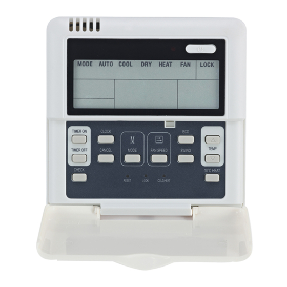
6. NAMES OF KEYS ON THE WIRE CONTROLLER AND THE KEYPAD OPERATION DESCRIPTION ON/OFF TEMP SET TIMER SET CANCEL MODE PAGEUP ALARM CLEAR PAGEDOWN QUERY ADDRESS / - CLOCK ADDRESS/+ LOCK HYSTERESIS ADDRESS SET TIMER SWITCH TIMER QUERY ADDRESS SET LOCK HYSTERESIS ①... - Page 11 “page up” and “page down”. There are Modes shifted sequence as follows: two possible inquiry sequences. 1).Error→protection →outlet water 1) Mode of KJR-120A air cooled modular temperature Tou→inlet water tempera- wire controller: ture Tin→outdoor ambient temperatures →...
- Page 12 ⑨ CANCEL button and protection information. Press the button can return to the ⑤ CLOCK button inerface previous and not save the Press the “CLOCK” button once 【Press setting information when the timer switch for the first time】, and enter to the is ON.
- Page 13 display the next address is 15. When there is only one wire controller, it Press this button for minus temperature is necessary to execute this setting, the at wire temperature setting mode. address of wire controller should be set Press this button for minus clock or time to '0'(main wire controller) .
-
Page 14: Operation Procedure Of Wire Controller
7. OPERATION PROCEDURE of wire controller is light, unit is start to OF WIRE CONTROLLER run, and display running status at wire controller. Press this button once again, ● Operation procudeure of mode unit will stop running. setting 1. Press MODE at shutdown status, you ●Operation procudeure of system could select appropriate mode as you information querying... -
Page 15: Fault Alarm Processing
(the parameter of δ ,Tj1 and Tj2 are the operation indicator share the same ,δ decided by the outdoor unit) LCD. 2:Some errors will be auto cleared after Unit start temperautre Unit start temperautre Ts+ + δ ≥ AL AL the errors are cleared, and some error Ts+ + δ... -
Page 16: Using Method
8. USING METHOD WEEKLY TIMER SET TIMER SET CLOCK SET Select week ADDRESS/+ ADDRESS/- CLOCK set week Set Period 1 start hour ADDRESS/+ ADDRESS/- ADDRESS/+ ADDRESS/- CLOCK ADDRESS/+ Set Period 1 start minute ADDRESS/- set hour ADDRESS/- ADDRESS/+ Set Period 1 end hour ADDRESS/+ ADDRESS/- CLOCK... - Page 17 Set Timer Period 2 NOTE Set Period 2 start hour ADDRESS/+ ADDRESS/- operating, Press "CANCEL", to turn back to the previous step or the normal display ADDRESS/+ Set Period 2 start minute ADDRESS/- interface. WEEKLY TIMER QUERY TIMER QUERY Set Period 2 end hour ADDRESS/- ADDRESS/+ Select query week...
- Page 18 simultaneously. It is not allowed to cut off NOTE the power supply separately. 1.Before power failure of the heating 5. When several wire-controllers are water system or wire controller, the wire parallel connected, the timing message controller memorizes the status of the communicating these unit automatically, and sets the water...
-
Page 19: Appendix 1
Appendix 1: Error of outdoor EEPROM Power supply wire phase error Communication error Error of total outlet water temp. Sensor(Be valid for main unit) Unit outlet water temprature sensor failure System A condenser temp. Sensor failure System B condenser temp. Sensor failure Error of outdoor ambient temp. -
Page 20: Appendix 2
Appendix 2: Error of waterflow detection (The third time) Power supply wire phase error Communication error Error of total outlet water temp. Sensor(Be valid for main unit) Unit outlet water temprature sensor failure System A condenser temp. Sensor failure System B condenser temp. Sensor failure Error of outdoor ambient temp.
Need help?
Do you have a question about the KJR-120A and is the answer not in the manual?
Questions and answers